
I've been thinking about the idea of scratch building a 1911 frame from a couple pieces of flat bar stock. Does anyone else see this being feasable?
A 1911 frame from 8 seperate pieces is possible and very simple with a bit of planning.:;):
I can sketch it up (roughly) and email it to someone with a way of putting it on a forum if you like.
Similar to a STI top end but the mag area and triggerguard etc is welded permanently.
Keep in mind that it will only be a sketch of the major components with no dimensions, they come from the normal prints you can get anywhere. This is more so a way I do it and you can decide for yourself if you can use the method.
First one I ever did was mostly handtools apart from a little mill time to do the rails.
Now have my own mill so that makes life easy.
And, I miscounted, actually it is 7 pieces.
The upper / rails and firecontrol area are the major item and everything else is just to make it look right.
Dustcover
2 grip side panels
front for the grip area
infill piece between the side panels internally and trigger guard
The above are positioned and welded to the solid upper section after all the hard to reach places are machined on the upper.
Bear with me while I sort all the computer stuff out and get it together so it makes sense.
Hello Mckutzy, yes the welds need to be reasonably good and preparing the joint before welding to ensure good penetration is a must.
These are welded using a small MMAW welder, nothing fancy, TIG or a small MIG would give better results and eliminate any chances of slag inclusions.
One of the reasons for making the upper from a solid block is to put those welded joints away from critical strength regions.
The dustcover is nothing to be concerned about but the joint at the sideplates is also reinforced again by the fillet of weld around the front strap that gets blended into the frame during final shaping, so a good size margin for error is there IMHO.
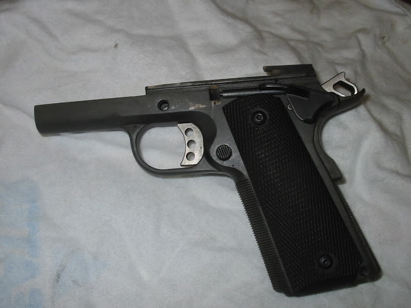
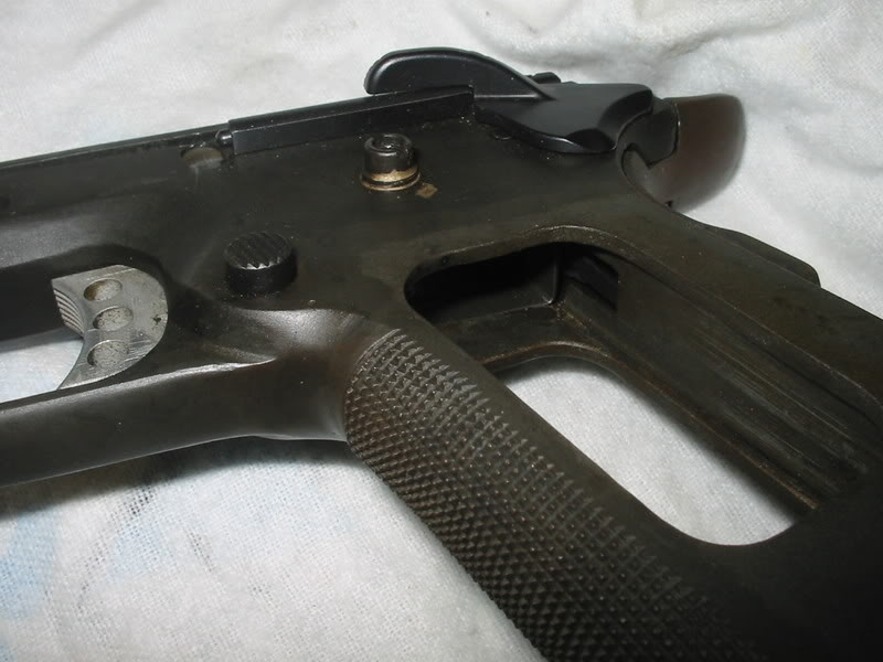
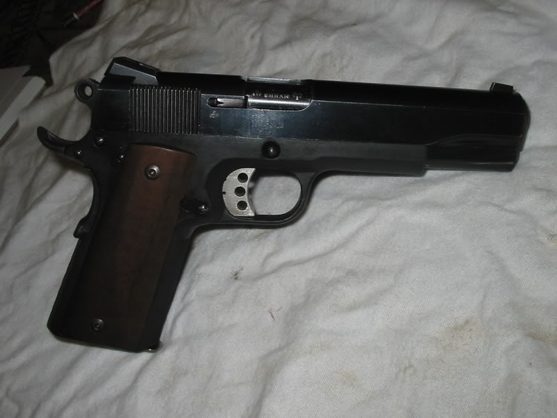
I have some photos of finished frames and a half done section to send to anyone who can put them on the forum.
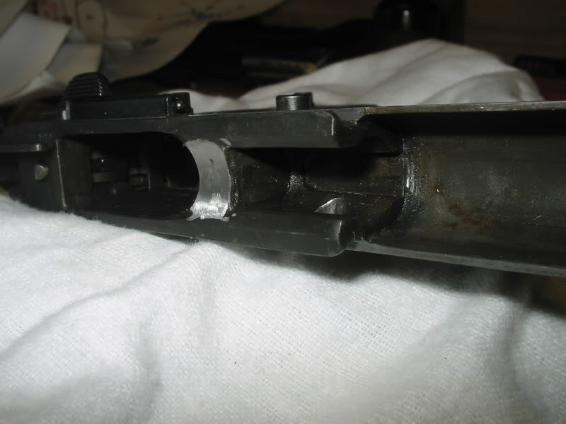
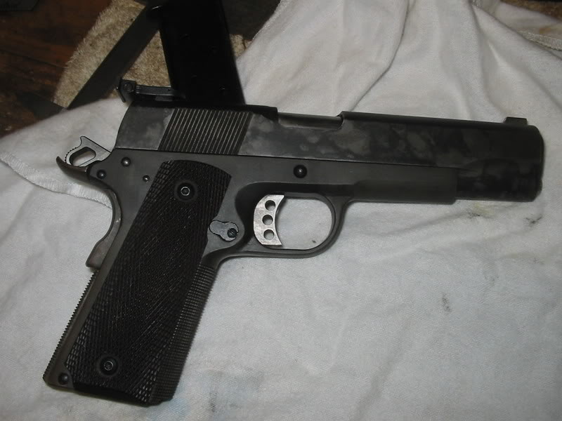
I have one pic of an upper partially done. The photo shows the trigger bow area.
Other shots show how it is possible to get decent results using this method.
To answer a question earlier from Brokengun, sorry, but there are no measurements on these. They are more like a rough sketch of what is in my head when I build a frame.
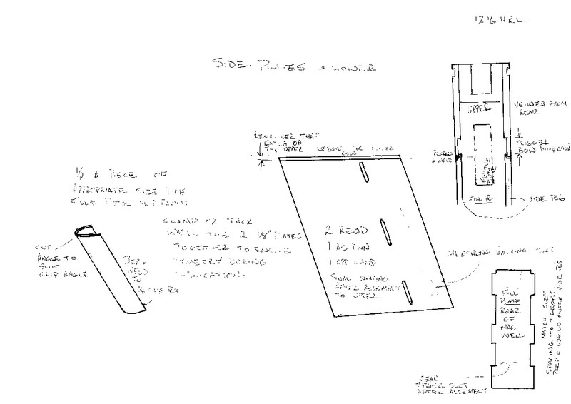
All the measurements come from the usual blueprints around the place and the only measurement on my sketch is to show the trigger bow slot being a bit deeper than a trigger bow to let the side plates ledge locate and form a nice square corner internally.


1216hrl -- do you use a jig to keep everything aligned when you weld the parts together?
Do you weld the pieces then drill and mill the various holes?
With this design, you could scale up the magazine well area and have a 1911 in 357 magnum or 7.62x25, yes?
Weld sequence that I use is,
fabricate the side plates and the filler plate as a unit then fit that assembly to the upper in the correct spot.
You could use a old magazine to assist here but it can be done using a ruler to align the rear of the magazine opening in the upper with the filler plate inner face and the ruler up the grip on the outside to make sure the upper is not canted over to a side as well.
Put the half round front of the grip on and weld that to the side plates and upper. Again, a old magazine can assist in the fitting process and make sure there is not to much filing to allow a mag to fit inside the grip or that you end up with excessive room in the mag well area.
Then put the duscover on and the trigger guard while the upper is clamped to a flat surface upside down (grip pointing up in the air).
I dont quench it but let it all cool slowly and naturally.
Failing to clamp the upper and dustcover down when doing the dustcover lets the it pull away badly from the slide at the front end due to weld shrinkage.
I leave all the holes till after the parts are joined and welded up then all the final shaping to make it pretty.
Theoretically you could make the mag well long enough to fit a 30-06 if your heart desired, I think you would need a slide made to suit any longer cartridge but wouldn't you?
.357 or 7.62 x 25 might work in a standard slide travel range but thats a whole different can of worms about pressures and strength requirements I would think.:D
Way to think outside of the box, I can see where anyone with a benchtop milling machine and a cheap mig could easily put this together. I would have never thought it possible to create from scratch a 1911 frame in a average homegunsmiths garage. But you figured it out, Nice job :D
I haven't got any work in progress apart from the upper I photograped earlier.
What I can do is draw up the individual items with some basic dimensions and maybe a exploded view type of sketch to show where they all fit together.
The way I do it is to leave a lot of excess on the stock material and trim things down after it is all welded and parts are starting to be fitted.
By that I mean things like the side plates hang way down further than they need to and are trimmed back once the magazine catch is positoned so that the magazine finishes flush with the bottom of the grips.
Sneaky things like that so that in effect you are more like sculpting away the excess steel rather than cutting stock material to a specific size.
The rear infill plate as a .07 ledge milled into it. is that .07 deep or .07 thick? and is that the bottom of the trigger bow slot?
That .07 ledge is on each of the side plates not the rear infill plate.
Please doublecheck all my dimensions in case I made a mistake.
If you have a look at the last sketch you can see I have noted that it is the near side sideplate and is colored the same as the sideplate on the main sketch
To the right of the main drawing is just a perspective view as you would be looking at it from the rear to see the infill plate between the 2 sideplates.
The other side plate has the same slots for the rear infill plate to locate into for strength and to form the lower section of the magazine well and the grip.
Then if you can imagine the .07 ledge and the depth of the upper block trigger slot combining to form the lowest ledge for the trigger bow to sit on you are on the right track.
This pic from earlier in the thread shows the trigger bow slot correctly position according to normal blueprints in relation to the top, or rail surface, but with "nominally" .07 extra depth compared to the trigger sitting in its position, to accomodate the side plate ledge.
This photo of the sketch that Zougou kindly posted first off shows at the top right corner, how the 2 side plates in combination with the rear infill plate are positioned to the upper block to form the trigger slot.
Oh just to be clear, That .07 can be absolutely any size you want it to be as long as the upper is matched to it.
My first one I made didnt have a ledge at all but that made it very hard to weld because the trigger bow slot leaves it very thin in that spot so I started putting a ledge there to make welding easier.
And the other part of your question as to how thick the remaining material at the ledge would be is determined by the size of the magazine well formed by the side plates and the rear infill, in relation to the width of the upper block.
1216hrl; The only copy of 1911 blueprints that I have are on a plain sheet of paper. I have to use a magnifying glass just to barely read it.
I can not find where to start cutting the magazine slot. On the drawings that you provided to board (thanks again). It show where the front dust cover meets the upper.
You provide a measurement of .361 to the barrel link hole that is .45" from the top. Could you please give me the measurement from the front of the upper to the front of the magazine opening.
I have found the measurement of .551 for the magazine opening width and an angle of cut for the magazine slot of 17.5 degrees, but i don't know where to start the cut.
Could you also describe how you cut the area for the barrel link area.
The reason that I am asking so many question is that I don't own a 1911 and I have no reference other than your guide and a few pictures.
Quote (brokengun @ June 16 2007)
1216hrl; The only copy of 1911 blueprints that I have are on a plain sheet of paper. I have to use a magnifying glass just to barely read it.
I can not find where to start cutting the magazine slot. On the drawings that you provided to board (thanks again). It show where the front dust cover meets the upper.
You provide a measurement of .361 to the barrel link hole that is .45" from the top. Could you please give me the measurement from the front of the upper to the front of the magazine opening.
I have found the measurement of .551 for the magazine opening width and an angle of cut for the magazine slot of 17.5 degrees, but i don't know where to start the cut.
Could you also describe how you cut the area for the barrel link area.
The reason that I am asking so many question is that I don't own a 1911 and I have no reference other than your guide and a few pictures.
Thanks Brokengun
Thanks Fuzzbean, hope you all dont mind the slight hijacking of the thread and the longish posts.
Brokengun, I really dont want this to sound pushy or saleman like but the best thing I ever paid for on the internet was membership of this site to access the library.
There is a pile of info in there and very good clear blueprints and other info on 1911's as well as a lot of other stuff, I dont think you would regret it and you will get so much more info.
To answer your questions, the starting point for the magazine slot in the upper is a bit of a hard one to locate.
The .361 and .45 measurements for the link pin hole, you should see on your blueprints, that hole center is the point I measure from to find the magazine slot. BUT it does depend on what set of blueprints you are looking at, some have the .361 as .364 and some dont show anything to help locate the mag well.
Depending on what blueprint you have, you should see, on the sectionised view, a measurement from the center of the link pin hole to the loading ramp which is angled variously at anywhere from 30 to 31.5 degrees at a distance from the link pin of .79.
Scribe that line on the outside of the upper block. and then reset your bevel square to the 17.5 degrees for the mag slot angle.
Now if your blueprint tells you that the 30 degree angle finishes at the top of the upper .25 back from the rebate for the barrel link area (behind the link hole) then that is a good place to start from or double check.
Adding up the measurements should put the forward most point of the loading ramp at 1.042 from the very front of the upper block. (.361 to link hole + .431 to face of the rebate where the barrels link lugs recoil to + the .25 to the front edge of the loading ramp.
Again dont trust my measurements, satisfy yourself that you are happy with and understand the why's of all these locations. I dont trust me sometimes so I dont expect others to take this as gospel.)
The closest I can come up with to now position the front of the magazine well is that the top edge of the barrel link hole is very close to the level that the 30 degree angle intersects the 17.5 degree angle.
So, I take away half the diameter of the barrel link hole from the .45 center measurement and from the top surface of the block and mark that on the 30 degree scribed line.
That intersection point is where the bevel square goes to scribe the 17.5 deg FRONT of the mag slot.
Measure back from that line half of the width of the mag slot (to find the center of the drill), and transfer the line to the top of the upper on the centerline and that "should" be the spot to drill.
I then use a 1/8" drill bit to drill the center pop at the correct angle and mill the top out at the 17.5 deg angle so a bigger drill doesnt wander off.
If you do drill it without milling away the slope first then start with a small drill bit and increase size gradually to reduce the tendency for it to wander off the spot.
If it does wander it will go into the area to be removed for the magazine anyway so just means extra file time or straightening it out with a 1/2" endmill in a drill press by plunge cutting if you dont have a mill.
Clear as mud?
The barrel link question I will describe in another post shortly if you have no questions about the above description.
Working things out from the various sets of 1911 blueprints available in the library can certainly take some time, but it is doable. There's a thread dating back about 5 years that talks about using a 5C spin indexer as the basis for a fixture to scallop the front strap... it's a pretty cool idea. I noticed, though, that the guy's approach was to lock a turned-down 9/32 rod into the front of the magwell and chuck it up in the indexer. The problem there is that the inside front of the magwell uses a .2775 radius and the outside of the frontstrap uses a 13/32 radius (.40625) and their centers aren't in the same place, so when you rotate the indexer the you're not spinning the frontstrap around on its proper axis. It took me over an hour to scratch back and forth to discover the offset between those 2 axes. My point is, it takes more than a single set of drawings from the library to figure out exactly what is what, and you need to toss Kunhausen in for good measure as well, as every little bit helps. Just my 2c.
FWIW I'm about 40% of the way along with designing the proper fixturing to do that front strap work with the indexer... I'll share the results when they're all drawn up.
I agree with Marvkaye regarding get all the info and cross checking it as much as possible with other sources.
The Kunhausen books are a treasure trove of information and worth the outlay to get them.
Sorry Zougou, I dont have a list of the drill bit sizes but all hole sizes are on the blueprints.
Now that I have a mill at home I do a lot more using it than on the first one I made, although I still like to do a lot of things by hand like the safety slot by drilling the main hole undersize and then filing the secondary cuts to shape and size. The rebate behind the safety slot is done using the modified cutters pictured in the build tutorial, in a pinch I guess it could be used on a drill press with a solidly set up table to hold the frame in position and draw the cutter up to create the recess for the safety catch retaining slot. I can't recall how I did my first one but there would have been a lot of filing dremeling and cursing to do that recess under the surface.
The vast majority of the final frame shaping I also do by hand using dremel and files with only the bulk of material removed by the mill rather than set up fixtures to machine cut the surfaces. (kind of lazy on my part because everytime I make one its going to be the "last one I make" so why make a jig or special fixture.) :p
The barrel link area on my design is easy to mill as the dustcover is not there to make the tooling overly long and induce tooling flex or chatter. The first one with out much mill time available to me was drilled just under depth required, then I cut the drill bit square to chase out the hole (should have bought a mill bit but I was dopey)and leave a flat bottom and then cut and filed the narrower slot to the top of the upper. Not perfect, and took a few tries before I was satisfied with the result but it was all I could think of at the time. Now I use the mill to do all of that and it is so much neater, easier and less stressful.
I am probably not helping Zougou's efforts much as my techniques are aimed at my "basic block" method and the hurdles in a 60% frame, holding it and machining deep slots and holes, was why I tried a scratch method in the first place.
One thing to consider if making the magazine opening longer is that the disconnector hole and sear pin holes etc would have to stay the same places as original dimensions to suit a standard slide.
Never having played with the 7.62 X 25 round I am not sure how much more if any the length of magazine opening distance would need to be.
Any moving of the sear/disconnector holes would also mean a longer trigger bow would be needed and then the disconector notch in the slide might be in the wrong place if using a standard slide.
Plus if the sear has to move back then the hammer also has to move back the same distance and then the hammer is further back from the rear of the slide than a normal frame.