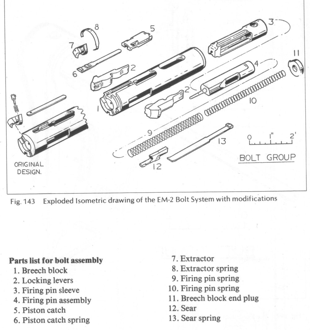
Thread: scratchbuilt roller locking
TRX
08-13-2010
[from a thread of mine elsewhere, that died out. Reposted here FYI]
---
Has anyone done a scratchbuild with a roller locked bolt?
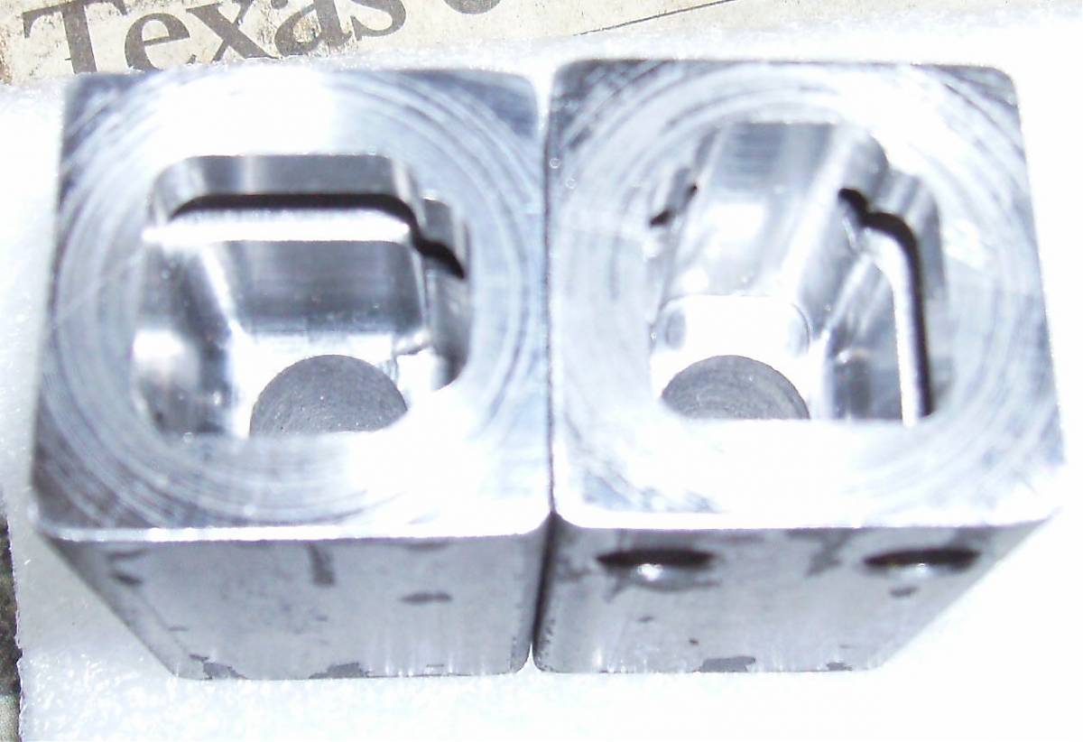
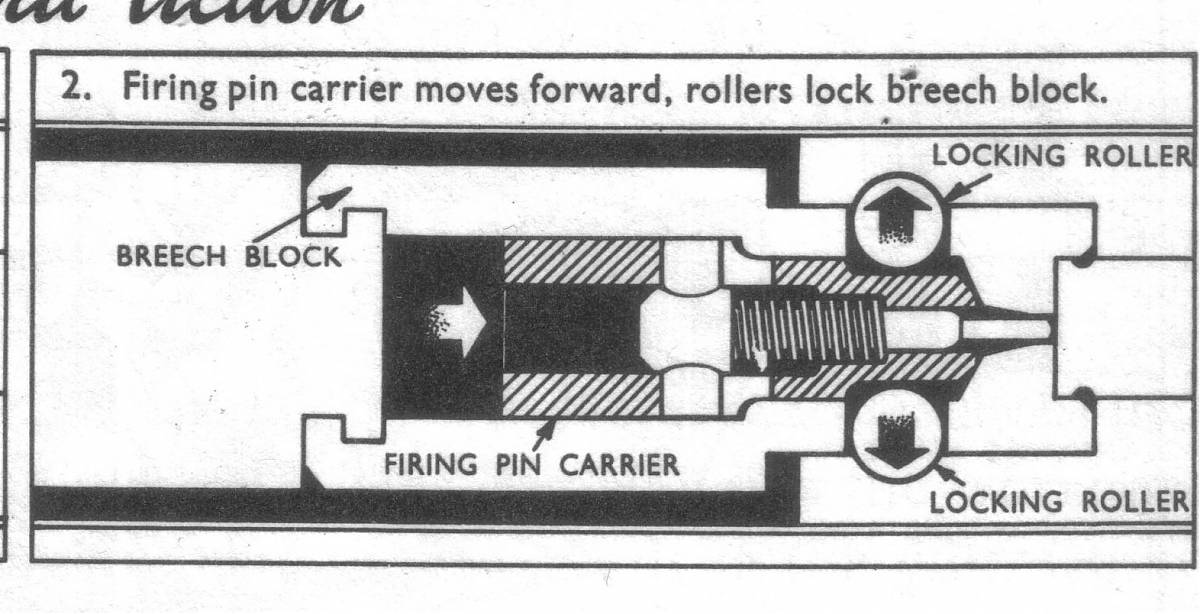
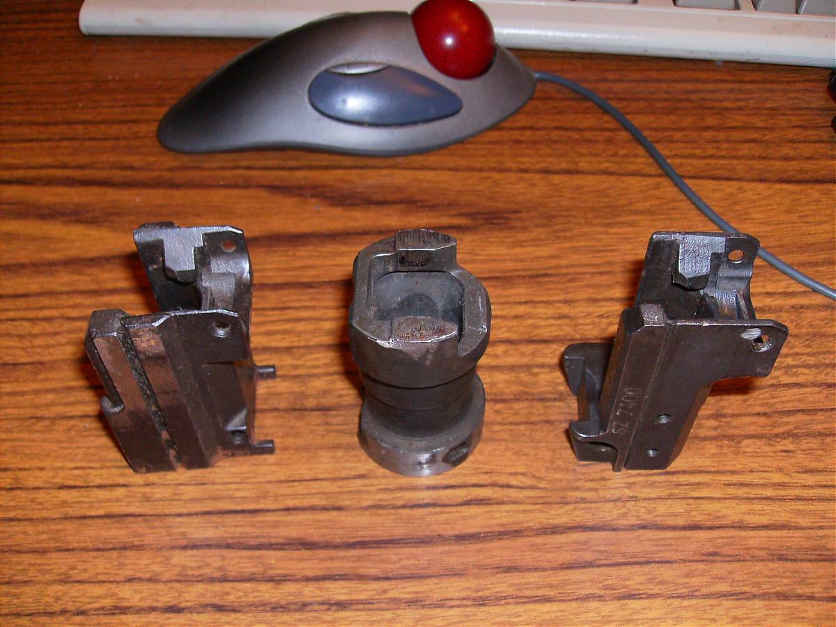
I've been looking at a book that covers the Enfield EM-1 prototype from the 1950s. It was a gas operated, roller locked setup. The bolt consisted of a tube that held two rollers, looks like they were about 5/16 x 3/8", and an inner wossname, firing pin carrier, with a wedge face to force the rollers out. The firing pin rode inside the carrier.
The gas system moved the firing pin carrier, which moved the outer sleeve. It looks like it was a very long stroke gas system.
From the drawings, it looked like about 1/3 of the roller was in the front trunnion when locked, so when the firing pin carrier moved back, the rollers just popped out of the trunnion of their own accord. There's no indication of anything like the fancy ramp angles a G3 or CETME uses. The trunnion otherwise looked pretty much like a G3 part.
The bolt tube carried the entire locking load; the carrier just kept the rollers pushed out. When in battery, the rollers were on a perpendicular surface on the carrier, so the camming action from the gas load just tried to pinch the bolt carrier; there was no angularity to move anything back.
The length of the carrier nose and the firing pin protrusion appear to be designed so that there's no chance of a firing pin strike until the bolt is fully locked.
I've been pondering this setup for a couple of weeks now. It looks like it would be easier to build than a turnbolt setup. The "lug" area of the bolt sleeve looks reasonable. You can buy proper roller bearing rollers from several sources; they're usually 8620 alloy or something similar.
The gas load on the locked bolt will try to spread the ears on the trunnion a bit. Theoretically, enough spread and you could blow the bolt right out. I found a G3 trunnion on GB for $15 to take a look at; it isn't here yet. The G3 is a roller-delayed setup instead of roller-locked, but I'd like to see how beefy they felt they needed to go with a .308.
Anyway, has anyone done this from scratch? Results? Comments?
---
I found "Full Circle: A Treatise on Roller Locking" by R. Blake Stevens while searching for roller locking stuff on the web. The going price seems to be $80-ish, so I logged onto the local library's web site and ordered it via Inter-Library Loan. Hopefully some library out there has a copy to share. If not, I guess I'll buy it.
---
Definitely let us know what's in "A Treatise on Roller Locking"--an awesome name, if nothing
10-4 I'm hoping it has some real information and not just pictures of guns that happened to use the system...
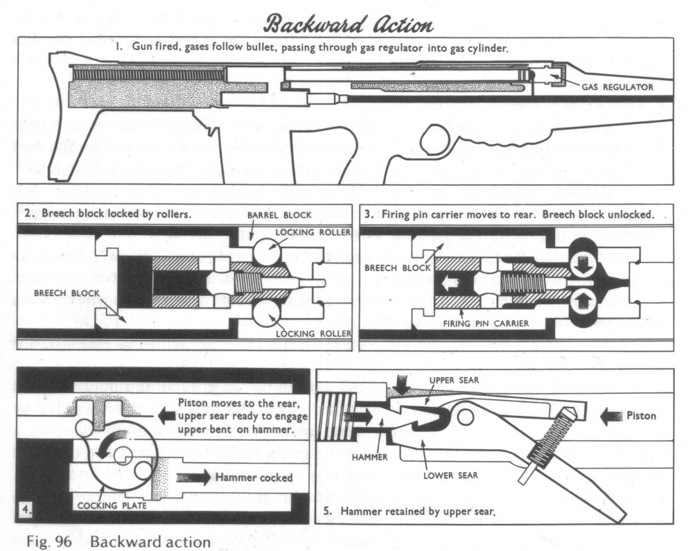
Roller locked uses the rollers to hold the barrel and breech together at the instant of firing; the locked-together barrel/breech assembly recoils backward until some sort of trunnion pulls out the rollers, and the chamber is opened.
The EM-1 used an ordinary gas setup with a piston. It slotted into the firing pin sleeve, which formed the locking wedge. When the gas pushed the sleeve back, the rollers popped back in, and then the whole assembly moved back.
The EM-1 sounds like roller *locked*, so I'm not sure how much the G3 parts
are going to help you.
Yes, locked. I'm not sure about the G3 trunnion either; when I ordered it I didn't realize the G3 was just delayed and not locked. If nothing else I can get the roller size and send it off to a friend who has access to various testing equipment to get the hardness and alloy.
Tricky part about scratch-building a useful roller locked gun would be that damn moving barrel--getting any accuracy would take some pretty sweet trunnions for the barrel to seat back into...
The EM-1 used an ordinary fixed barrel. I'm starting to get the impression that it was, if not unique, an unusual implementation of roller locking.
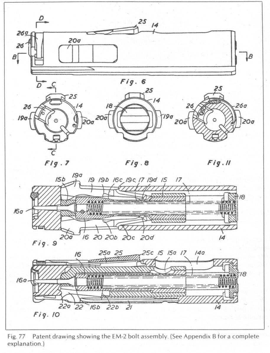
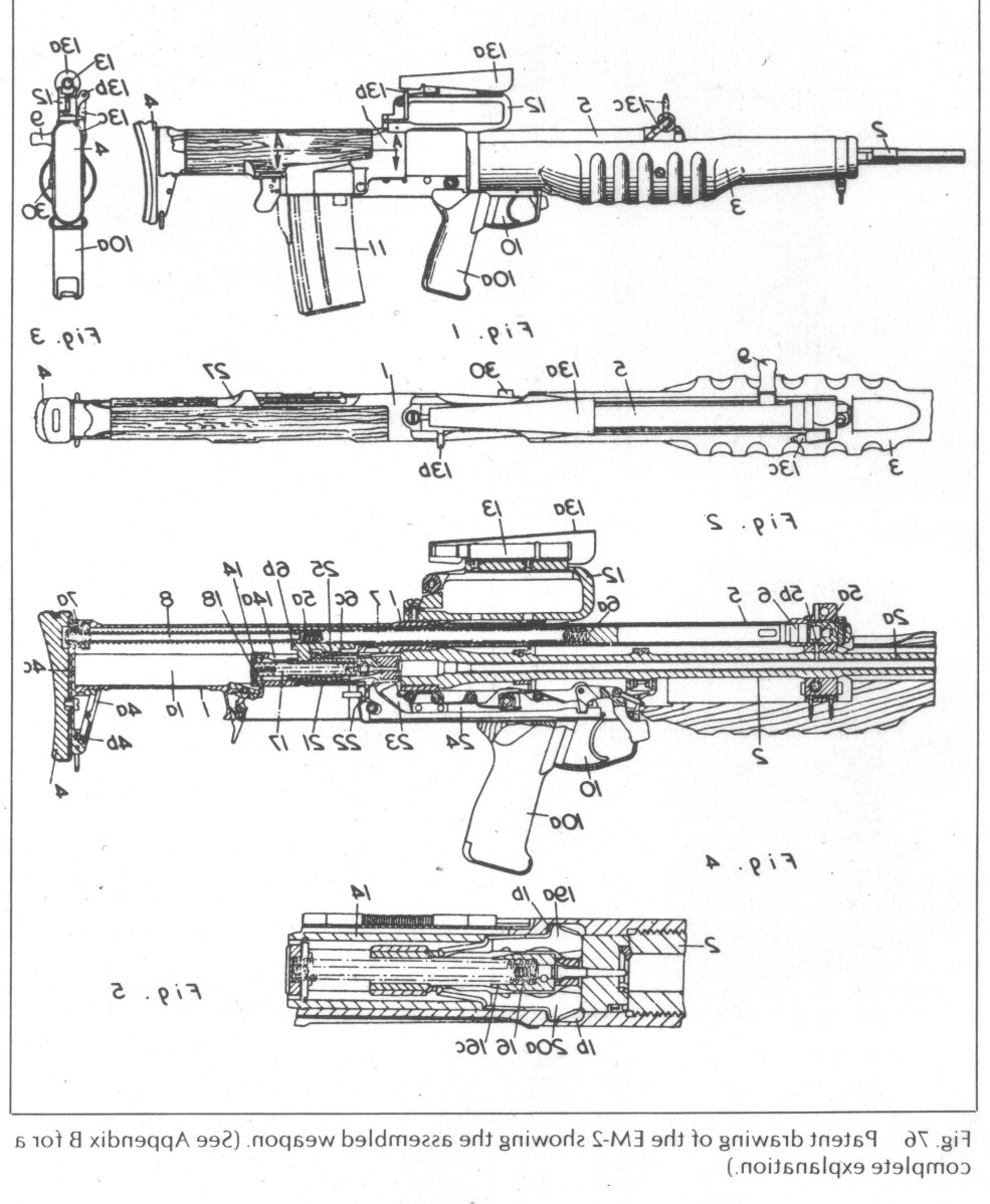
At the moment the only detailed roller locking information I have is the pictures in the book "EM-2 Concept and Design" by Dugelby, which has to go back to the library tomorrow. The EM-1 prototypes were roller locked, the EM-2 used lever locks. Doable, but way more complex to build than rollers. There was no explanation as to why they picked the EM-2 over the EM-1, but there was considerable politics involved. And as far as manufacture... the Brits were never afraid of complexity. Where an American car would join two parts together with a single coarse-thread bolt, a British car would use three fine- thread studs with flat washers, lock washers, castle nuts, and cotter pins...
---
might be easyer to use the locking flaps like the Ruskies used in the DP-28 and a lot saner.
I discovered those while googling for roller stuff. I've seen some pictures of the bolt assembly, but just external pictures of the receivers. If you can point me to some detailed views I'd sure like to see them.
I'm guessing the backs of the flaps are shaped to cam out of their recesses, and do so when [a locking wedge?] releases them. I've managed to sketch a few designs that might work, but they would all be impossible to machine without building customer machinery to cut the flap recesses. Obviously the Russians and Germans had a better idea...
---
The G3 trunnion showed up today. It's sitting on the desk next to a Yugo AK trunnion. They're about the same size, but the Yugo trunnion is noticeably beefier. They both use barrels of similar diameter, and the G3 barrel is pinned in place like (most) AKs.
The roller ramp area in the G3 is contained within "wings" off the back of the trunnion. They're joined by a flat web across the bottom. I guess you could also look at it as a 3/4 circle opened at the top; either way, the tops of the wings are unsupported.
There are marks from the rollers. They're much smaller than I expected.
There are machining marks on the outside of the G3 trunnion. I can't tell if it started off as an investment casting or bar stock, but the OD was finished off with dull tools. The roller ramps and inside areas of the trunnion are very smooth, apparently ground. The "wings" are tall enough to handle the roller tracks and sufficient overtravel for a small grinding wheel to finish the ramp area.
I *think* I see a pair of Rockwell dimples on the back of the right wing.
---
The library emailed me back; that book is not available by Inter-Library Loan.
I've added it to the "discretionary budget" list, but it's pretty far down, considering the bits I need to finish various gun projects.
I'm still going to keep an eye out for roller locking stuff, though. It seems like such an elegant solution...
TRX
08-14-2010
Originally Posted by mrtank
Cutting the locking recesses so that they have a uniform contact with the
rollers and not only small porting would be rather tedious.
I think I have that part sussed out. To do an EM-1 style roller lock I'd drill and ream the trunnion from above to create the lock recesses, drill the sleeve and file the roller recess square. The roller wedge would be simple lathe and mill work. The attraction of a roller lock is that it's *much* simpler than a turnbolt.
To me for a locked semi from scratch with It would be less trouble to go with a bolt with locking flapper lugs like in the G43, EM-2, Degtyarev DP-27, RPD, etc.
Looks like the EM-2 was a derivative of that. I've been calling it a "lever lock" since I hadn't come across any pictures of the "flap" setup.
iB::Topic::Anyone make a roller locking pistol or rifle? That's the thread I was thinking about. I have been thinking about both the stamped steel tilting bolt and the flapper lug bolt for quite some time, and some day I hope to getting around to making some chips.
I'll scan some of the EM-2 pictures I got out of that book. They might help you.
TRX
08-14-2010
EM-1 locking system
Enfield EM-1 roller lock:
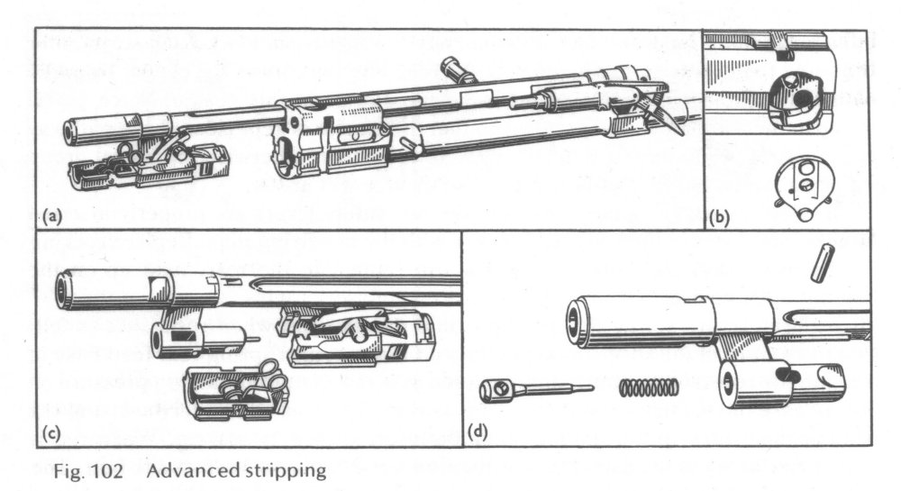
Unfortunately, nothing about the extractor and ejector bits. I've been scratching my head on how to fit something into the available space.
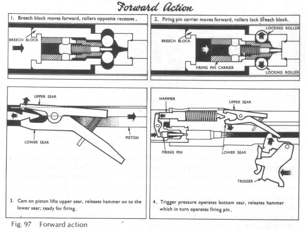
Most of the weird monkey motion is due to the bullpup arrangement. Enfield chose to use a somewhat, ah, unusual arrangement. The sear is offset to the right, very long, and reaches down to the trigger assembly. They also used a striker and a rocker arm, unique, as far as I know. Fortunately I'm not interested in duplicating any of that part.
The centerlines of the rollers ride on the sleeve. Around 1/3 of the roller sticks out into the trunnion. Gas load makes the roller push against the nose of the firing pin sleeve; there's no rearward thrust through the roller action. Gas load goes from the front of the sleeve to the forward sleeve cutout, across the roller, and to the trunnion.
The firing pin sleeve moves back, the rollers cam in through the sleeve, everything unlocks. I'm not particularly thrilled at how the rollers can touch the firing pin. I imagine the unlocking would be somewhat brisk, even though theoretically the left and right rollers wouldn't put any bending force across the pin.
You could drill and ream the roller slots in a round chunk, then bore and hone it to size. Voila, trunnion.
TRX
08-14-2010
EM-2 locking system:
Enfield EM-2 lever lock:
Both the EM-1 and EM-2 used stamped steel receivers. There was no useful information about that in the book; I couldn't even tell if the rollers locked into a trunnion piece or against the sides of the receiver itself.
TRX
08-14-2010
Originally Posted by mrtank
Sounds like a plan. You may look at making the barrel journal diameter
larger than the locking square hole for the bolt, to simplify
machining.
I wasn't planning on doing a square hole. Sketching it out, it looks like reasonable contact could be had if everything stayed round.
What book was that? I need to get one, I have a thing for the .280 British, something that could have been. I think RCBS has dies for the .280 British but I don't know what version...
It's the Dugelby book from Canada. There's quite a bit of stuff there, even records from Parliamentary debates, and pictures of many of the prototypes. Just not much on the internals.
TRX
08-15-2010
A square hole minimizes the distance the rollers have to move from locked to
unlocked. With HK-sized rollers (look to be somewhere between 3/8 and 1/2") a
round trunnion and bolt sleeve would add, oh, maybe half again as much travel.
For a roller-delayed setup like a G3 this would be bad - the ends of the trunnion hole and the center of the bolt sleeve would see high localized pressure as the centerline of the roller moved from locked to unlocked. It'd probably beat up the parts.
With gas operation I don't see that this would be a big problem as long as the gas system wasn't too violent. All the gas system needs to do is cam the roller out of the trunnion and kick the carrier far enough back to cycle another round. I noticed the EM-1 had a really long spring and a lot of carrier travel, probably so it only needed a relatively gentle kick from the gas system.
I guess it *would* be possible to do a square trunnion - other than a mill
step, it would work just the same as my round idea. Drill and ream the locking
lug recesses, bore the inside, then add an extra step to mill flats along the
inside of the recesses. With a 1/4" end mill the overtravel would work out
okay. I've been sketching with the bolt sleeve locating the rollers
vertically, so a longer roller track than needed wouldn't hurt.
Hmm... might just as well go with a square trunnion then.
TRX
08-15-2010
I see what you mean about the extractor; for some reason I didn't pick it out
of the drawing. The sliding block setup seems to be popular on high-end rifles
nowadays. Running a tiny little cutter to do the notches would take a few
practice parts to get the speed and feed right. It'd be a snap with EDM... out
of my price range, though.
I bet you could just buy the extractor piece from Numrich.
TRX
08-15-2010
On your drawing you show the roller locking area as smaller than the barrel
hole. It would be easier to make the other way around - and that's how my $15
G3 trunnion is arranged.
The G3 trunnion, by the way, looks positively flimsy compared to a Yugo trunnion.
TRX
08-15-2010
Originally Posted by [486]
Use an ejector rod like a MAC. Then you just need a 1/8" or so hole through
the bolt.
I was thinking of a spring-loaded pin like a Savage, but a MAC style rod might just work...
TRX
08-16-2010
Originally Posted by mrtank
The bolt is going to be awful busy with the rollers and the firing pin and the
cam to engage the rollers.
Yes; that's the downside. But probably cheaper than the EM-2 bolt. According to the Dugelby book the EM-2 bolt cost almost fifty pounds sterling to make;. The exchange rate was one pound to three 1950 US dollars; $150 went a long way in 1950.
TRX
08-16-2010
Originally Posted by mrtank
with using the rollers you are going to be using a lot of room in the bolt
head directly behind the bolt face.
True. The rollers wind up about 1/2" behind where a regular bolt's lugs would be, and the nose has to be extended to get room for the extractor. Not a big deal to me.
I for one would dread the though of making the bolt head getting it setup that the rollers work perfectly.
The only important dimension is the distance from the loaded area of the square roller hole to the front of the bolt. It would probably best be broached. The locking recesses in the trunnion are no problem; either move the table the proper distance or use a rotary fixture and just flip the part over.
Then when you are setting up the ejector there is an error in alignment ect.. and you have to start over.
Well, that's all part of development! I was imagining that if I built one I wouldn't bother with an ejector or extractor, just build something I could strap to an old tire and fire with a string. I'm more worried about the camming effect of the rollers spreading the trunnion and letting the bolt pop out than anything else. But looking at the G3 trunnion, it couldn't really be much of a problem...
TRX
08-17-2010
Originally Posted by [486]
An AR type plunger ejector needs a cross pin for retention though, a MAC
style ejector pin just needs a through hole. I can see though how making a
through hole would be tough, what withe the locking wedge...
Remember, the firing pin carrier/locking wedge sees *only* a compressive load where the two rollers try to pinch together when the bolt assembly is locked. There's no load on the rest of the wedge ahead of that point; it's just there so the rollers don't fall out on the inside when unlocked.
The firing load is taken by the bolt sleeve, between the case head recess and the foreward parts of the roller recesses.
The load is also basically in compression, as opposed to shear in a common lug-style bolt.
Maybe just go with what I think the G3 has and do a fixed ejector on a pivot and a spring pushing it up against the bolt. Then you don't have to slot the carrier and all that and you still get most of the simplicity of it.
The Enfield appeared to use a pivoted, spring-loaded ejector mounted in the receiver. If I read the drawing right it was like my Ross receiver; the lever was sprung against the bolt body, and as the bolt moved back it would press up into a slot in the bolt, so the nose could ride up into the case head recess. The bolt nose would have to be long enough so the recess didn't get between the rollers when the bolt was locked, though.
TRX
08-17-2010
Originally Posted by mrtank
Could make it out of mild steel to accelerate any ware or structural
problems.
Might be well worth the "wasted" effort. Cheap, easy-to-machine 1018 or 1020 steel would also let you sort out your machining steps and fixturing. Even if the first shot blew the bolt right out of the trunnion, it'd give you at least one failed part to examine. My guess is the first problem would show up as dinged grooves in the bolt sleeve from the rollers pounding the soft metal.
I'm still thinking plain old 4140 should be enough for a fully-locked action.
TRX
08-17-2010
locked vs. delayed
I think some people are getting confused by the way a G3 works vs. the way the
EM-1 worked. The difference is in the firing pin carrier (EM-1) or locking
piece (G3).
The rollers on the EM-1 ride on a flat that's parallel to the barrel when the bolt is locked. The rollers just sit there in compression when the rifle is fired; there's nothing making them move. A gas system moves the firing pin carrier back to unlock the rollers.
The G3's rollers sit on a ramp on the front of the locking piece. When the rifle is fired, friction keeps it locked for a split second, then the ramp angles spit the rollers inward. The bolt spring increases the delay.
Hmm, I bet you could just use a G3 trunnion and make a new bolt head and locking piece without the ramp... the G3 roller recesses are more complex than simple semicircular cutouts, but that might not be a problem.
TRX
08-17-2010
What's why I was thinking about extending the nose and using a Savage-type pin
ejector. That eliminates any drillings or cuts in the loaded area... of
course, you wind up lengthening the bolt stroke to compensate. No free
lunch.
In the pictures, it looks like the roller cutouts in the bolt head are simple rectangular holes with no cam angles. If true, it might be possible to just make a new locking piece for a G3 trunnion and bolt head. Anyone have a G3 bolt head for sale cheap?
TRX
08-17-2010
Originally Posted by mrtank
For cheep I would say go CETME bolt head.
[URL]https://www.apexgunparts.com/product_info.php/cPath/23/products_id/57
Well, dang. $30 for a complete bolt head and $30 for a trunnion. I can swing that.
TRX
08-17-2010
There must be some pieces tack welded inside; at least, from the pictures I've
seen, it looks like the purpose of the stamped grooves is to keep the rollers
from falling out as the bolt travels back.
TRX
08-20-2010
Right now it's starting to look like a build could be greatly simplified by
using a CETME trunnion and bolt head with a custom (or modified) locking
piece. I'd still like to do one from scratch, but the CETME parts are so cheap
it's crazy not to at least give them a try.
Thinking about the ramp angles for the locking piece, 45 degrees looks like a good place to start. The ramp angle has to force the rollers out when the breech closes, uses only pressure from the recoil spring. The ramp angle is irrelevant on the opening cycle since the trunnion recesses will shove the rollers in.
TRX
08-20-2010
Originally Posted by vz58
1. This is a VERY simple machined part, the drawing is off as teh roller
opening should go all the way to the top so no broaching is needed.
If the roller slot goes all the way from top to bottom, you'll have to vertically locate the rollers some other way. Hmm... some simple pins might be enough; there's no lead on the bolt sleeve behind the front roller contact area. You could use any number of other solutions - flat springs across the top and bottom, or guides in the receiver.
edit: no, wait, now I see what you've done - the locking piece is attached to the spring doohickey, which caps off the roller slot. The width of the carrier is enough to keep the rollers from falling out. Nice.
TRX
08-30-2010
I finally got a chance to hit an AK (Romanian) trunnion and the G3 trunnion
with my favorite 8" Nicholson file.
The AK trunnion is quite hard, but I was able to put a small notch in it with enough pressure. Technically it can be filed, but the suck factor would be pretty high.
The G3 trunnion, on the other hand... any place I tried, the file skittered off. Didn't even scratch the surface finish. I thought it was some kind of Parkerize, but I guess it's how the raw metal looked when it came out of the oven.
Anyone have access to a Rockwell tester? It would be nice to have some real
numbers here.
TRX
Century's monthly sale catalog has CETME parts. $75 minimum order on parts...
but they have CETME front trunnions for $4.95, and all the parts to build a
bolt for $20-ish.
I'm still interested in DIY, but I might take a side trip with a gas-operated rifle using a CETME trunnion and bolt pieces. I can make a parallel-sided "locking piece" easily enough, I think.
TRX
09-16-2010
I wasn't planning on building a CETME, just using the CETME trunnion and bolt
head.
I was thinking either "tube gun" or "sorta-PSL-ish." A tube design always seems to turn out to need housings or guides of some sort to hold the rails, gas system, and trigger group, at which point the Kalasnikov "box" receiver starts looking really simple and easy to make.
The G3 trunnion I have could be pressed and spot welded into a square adapter trunnion, which would then be riveted to an AK-type sheet metal receiver. Or I might come up with some other idea.
I was thinking about waiting until the pieces get here to look at the bolt face and see if I could do a 7.62x39 or 54R with one of those 20" Green Mountain barrel blanks I have on hand, but the Voices have been reminding me that I'm set up to form .30-06 into 7.65x53 Mauser for my 1891 Argentine. I've never heard of anyone doing an autoloader in 7.65.
The 7.65 also runs at a lower pressure than the .308. There's no SAAMI spec, but I handload 7.65 anyway.
One of the reasons I'm thinking about the CETME bits is that they're known to
work, even with high-pressure military .308. Once I have a shootable rifle, I
could build my own bolt and trunnion. Doing them one at a time would make it
simpler to debug things, and fewer parts to sweep up should it auto-
disassemble during testing... and if I ran out of time or enthusiasm for the
DIY roller project, little would be wasted since I'd still have a shootable
rifle.
TRX
09-29-2010
Okay, I've spent a couple of weeks rabbiting off down the CETME/G3 path. I
don't see any technical problems with making a new locking piece and going to
gas operation, and doing so would let you dispense with the fluted chamber,
which would let you pick from a wide range of cartridges, not just .308.
I even went so far as to dig a box of 7.65 Argentine from the junk room and check them in a G3 mag - they fit fine, despite published dimensions. There are some of my reloads; I loaded them to the dimensions in my old '70s Speer book, which I can't find at the moment. I may have loaded them short for some reason. I also have a dozen-odd military cartridges made in 1893, the remains of a box of 20 I bought back in the '80s. Anyway, no problem building a 7.65 CETME...
However, I have too many other projects started to do this, so I'm going to set it aside and concentrate on DIY, which was where I started from. Shortcutting with a CETME trunnion and bolt assembly leads me inexorably back to a gas-operated CETME, which, while I think it would be really nifty, isn't the DIY I was looking for.
---
I have several pages of drawings for roller bolts and carriers, but vz58's design offers substantial advantages as far as practical construction. Unless some blinding inspiration strikes I'll use that, along with the square trunnion I've been doodling.
TRX
10-03-2010
Okay... unless my eyes are crossed there's a problem with vs58's bolt
arrangement.
On opening, the bolt carrier moves back, the rollers slide down the ramps, the bolt carrier hits the back of the bolt body, and the whole shebang moves back to open the breech. No problemo.
On closing, the bolt carrier moves forward... pushing the rollers out and then dragging along the bolt body. The assembly slams into the trunnion and stops out of battery.
Putting a bevel on the trunnion won't help since the rollers will be riding the parallel portion of the locking piece; they can't move in because they have no place to go, unlike a G3.
What's needed is a light spring between the bolt carrier and bolt body, to force them into the "unlocked" position until overcome by the recoil spring, which would be much stiffer. In this case, the unlocked bolt would move into position and then the carrier would continue moving to lock the breech.
What I came up with is a concentric spring arrangement up top, with a bobbin and fin. It's one of those things that's very simple to draw and difficult to describe. I'll put up a picture later.
vz58 mentioned roller retention as a problem with his design. It looks like it
could be dealt with the same way as a G3 - a couple of dimpled spring steel
pieces should do. If the roller slot was tall enough for the rollers and
springs, no special cutouts would be needed.
vz's design had the firing pin holding the bolt carrier and body together.
This would work, but I still think of a firing pin as a delicate piece. I kept
trying to sketch some kind of slot and screw arrangement to hold the pieces
together, with the slots on the bottom. I didn't like that because the whole
mess has to slide over the top cartridge, and it could damage the brass.
Finally I realized I could just run a single pin or socket head screw through
a slot in the side and into the carrier. You only need one; the carrier and
body can't get cocked enough to come apart.
I finally found my "sporting rifles breakdown" book, then did some web
searching. I'm still liking the Savage ejector and extractor setup. A spring
loaded pin in the bolt face is the ejector, and a sliding block, ball, and
spring for the extractor. The whole mess, brand new, less than $20 from
Midway. Downside: the T-slot for the extractor will be very difficult to
machine. I think Savage either uses a special machine and tooling or EDMs it.
If I cut away the rim around the bolt head opposite the extractor, I could use
a homemade broach or "safe" file to cut the grooves. Still thinking about
that.
The current design has a squared-off bolt nose that goes into a squared hole
in the trunnion. I'm thinking drill four 1/4" holes to make the corners, then
use a 1/4" end mill to remove the flat sides. Then bore the hole for the
barrel.
The left-right bolt to trunnion clearance is almost irrelevant, since the bolt is centered up by the locking lugs. I don't know what to allow for vertical clearance yet.
For a prototype, a whole lot of machining could be skipped - ejector,
extractor, bolt spring bits, body retention pin, etc. and the action could be
worked by hand and the empty tapped out with a cleaning rod if necessary. For
that matter, the recoil spring and the whole gas system could be eliminated,
since I'm only interested in validating the action design.
TRX
10-03-2010
So that's how the G3s do it? I actually considered that briefly, then wondered
if the locking piece might turn the rollers into a one-way sprag. But just
running some rails inside to keep the rollers pushed in would simplify the
heck out of things. Thanks!
TRX
10-03-2010
Originally Posted by vz58
Roller retention can be done by the little plate or spring but we are
adding extra machining.
It can be done without machining. The pictures of G3 parts show dimples on the ends of the rollers, with a flat crosswise piece of spring steel with two dimples. The flat springs and dimples keep the rollers from falling out.
We could do something similar. Instead of cutting slots for the springs, the roller cutout depth could be set to accomodate the springs too. I'm planning around G3 rollers; for a couple bucks each for something with the known proper material and heat treat, it seems to be a bargain.
TRX
10-09-2010
Okay, here are the trunnion ops:
4140 block, 1-3/4 square, 2" long
1) mill or lathe: square ends
2) mill or DP: drill two holes for the locking lugs, all the way through. Ream to 8mm.
Going all the way through eliminates sharp edges where the holes would stop, eliminating a possible stress riser. It would also provide a clear path for dirt or grit to exit (or enter...), and would allow easy cleaning by running a brush through.
Stopping after clearing the locking area would make the trunnion stronger. I'm sidestepping the issue by throwing lots of metal around the area, which adds weight and may complicate heat treat.
3) mill or DP: drill four 1/4" holes in a square in one end, for the corners of the bolt pocket
Theoretically this step is redundant, but when making deep side cuts with small end mills on my old manual equipment, I have an clumsy tendency to break end mills. So removing less metal helps.
4) lathe: put in 4-jaw chuck, drill and bore to barrel OD
5) mill: use 1/4" ball end mill to square up bolt pocket.
Ball milling will give us a radius where the square and round holes meet, to prevent stress risers
The square pocket isn't really critical in size, as long as it's large enough to clear the bolt head. The bolt is located vertically by the carrier and horizontally by the locking piece wedging the rollers out. "Isn't really critical" doesn't mean sloppy loose, at least horizontally, because the line of contact with the roller has to stay inside the bolt nose, and preferably not too close to the outer edge of the pocket.
6) mill: flip part over, reach into barrel hole with a keyseat cutter and make rivet pockets, AK style
7) heat treat to a bit harder than an AK trunnion; say 41-42Rc.
The rollers have more area than the AK's locking lugs, but there's more pressure due to the angles involved. Trying to figure this out makes my head hurt, so I'm going to go empirical here. Make four or five trunnions in a batch, then heat treat each one differently, until I find what they need.
I'm pretty sure the 41Rc is too soft, but you have to establish a baseline somewhere. I think the reason the HK trunnions are so hard is because their rollers actually roll, under load, and they're rolling across any grunge that's in the way. With the gas-operated design, the rollers just pop in and out of their recesses without rolling, and the only load would be residual gas pressure as the bolt opens. So I'm pretty sure the trunnion doesn't have to be nearly as hard as a G3.
This is for the test trunnions. For the "real" trunnions I'd add some wings to
the bottom for mounting rivets and an extension on the top to retain the top
cover.
edit: unlike a G3, this design is square at the back, wrapping the locking area 360 degrees for more strength.
TRX
10-09-2010
The length of the bolt nose - the distance from the cartridge face to the
front of the roller locking slot - probably doesn't need to be more
than a quarter inch or so by the SWAG-O-Meter. But the nose has to be longer
to acommodate the extractor and ejector bits. I can't nail that dimension down
until I get the actual bits on hand, so I have them down for the next order I
make from Midway.
I want the nose as short as practical, to reduce bolt travel (the longer the nose, the more travel required, to clear the back of the magazine when cycling) and to reduce firing pin length. I've never been a fan of skinny firing pins, and the front of the pin will have to be skinny to give room for the rollers, and long enough to reach from behind the rollers up to the primer.
For the development parts I'm not going to worry about an extractor or
ejector. Just some kind of stub receiver to hold the trunnion, simplified
bolt, and simplified carrier together and a means to strike the pin.
TRX
10-09-2010
roller retention
There's another way to hold the rollers than the G3 springs. Given custom
springs would have to be made, it comes out to about the same amount of work.
All we need to do is provide something to block part of the pocket opening. I'm thinking of a metal strip slotted into the side of the bolt, with the chamfered end projecting into the slot as far as possible without interfering with the roller in its locked position. Probably just hold the strips in their pockets with small countersunk rivets. Then the rollers could only come out from the inside, when the bolt and carrier are disassembled.
You know, I've done a fair amount of gunsmithing by now, but there's a big
difference between modifying or copying an existing design and coming up with
something from scratch. The sheer amount of detail work was more than I
expected. I was aware of most of the problems up front, but I wasn't prepared
for the way all the different problems interlock. Change one thing, three
others change to along with it, and you have an avalanche.
TRX
10-11-2010
Hmm, looks like an Enfield SMLE extractor might also work out. It fits into a
5/8" long bolt head and requires only a simple slot and a hole for the pivot
pin or screw. It would probably be easier to implement than the Savage sliding
tab.
The extractor spring in the SMLE is housed in the big lump of metal that hangs off the side of the bolt head. I think I could use a cutoff tool to put a groove around the end of the roller bolt head and use a springy wire ring to act as a spring. The groove would be in the unloaded area of the bolt head, so strength wouldn't be impaired.
A piece cut out of a coil spring of the right size would work.
TRX
10-11-2010
Hey, if anyone has any G3 or CETME bits laying around, can you tell me how
long the rollers are? I've found lists of the various diameters, but I need to
know the length to do further sketching on the bolt carrier.
TRX
10-11-2010
Oook-kaay. I was ordering some AK rivets from McMaster a little bit ago, and
ordered a piece of 4140 square bar to make the bolt body from. I'd just
finished the basic dimensioning this morning.
I'm finishing up the order list from Wholesale Tool; I've included a 1/2" 2- flute end mill to hollow out the bolt body, a 1/4" carbide ball mill to finish out the cavity inside the front trunnion, a fresh 5/16 2-flute mill to cut the roller slot, and an 8mm spiral flute reamer to finish the roller pockets. And a 45-degree cutter to do the angles on the locking piece. I could fixture it in the mill vise, but I decided to splurge on the cutter, since I can use it on other projects too.
I've also finalized the ejector mechanism - I'm going to slot the left side of the bolt head for the blade. Zillions of bolt action rifles slotted the locking lug for the same reason. I came up with two versions of the ejector - one uses a spring wire with an anchor screw. If it works, it will be a very elegant and simple solution. If it doesn't work like I want, I have a conventional sprung blade design, but it will take a lot more machining time.
I'd been assuming the plunger ejector would fit in the bolt head, but I'd forgotten the spring will take up way more room than just the ejector pin itself. Ah, well. Compromise is the essence of design.
The stack of pages paper-clipped together is being consolidated into a notebook.
Yes, we're having fun now...
TRX
10-11-2010
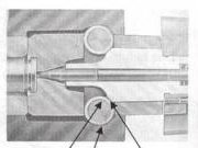
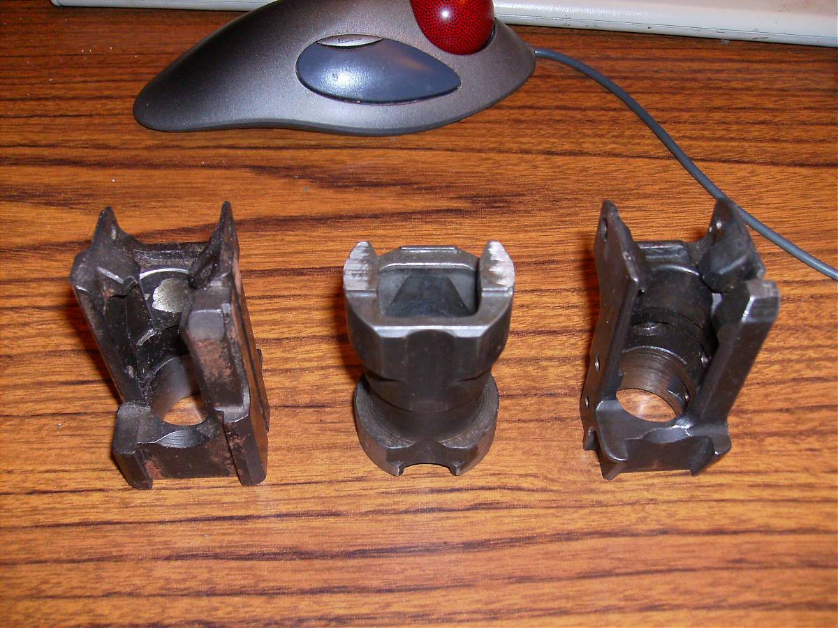
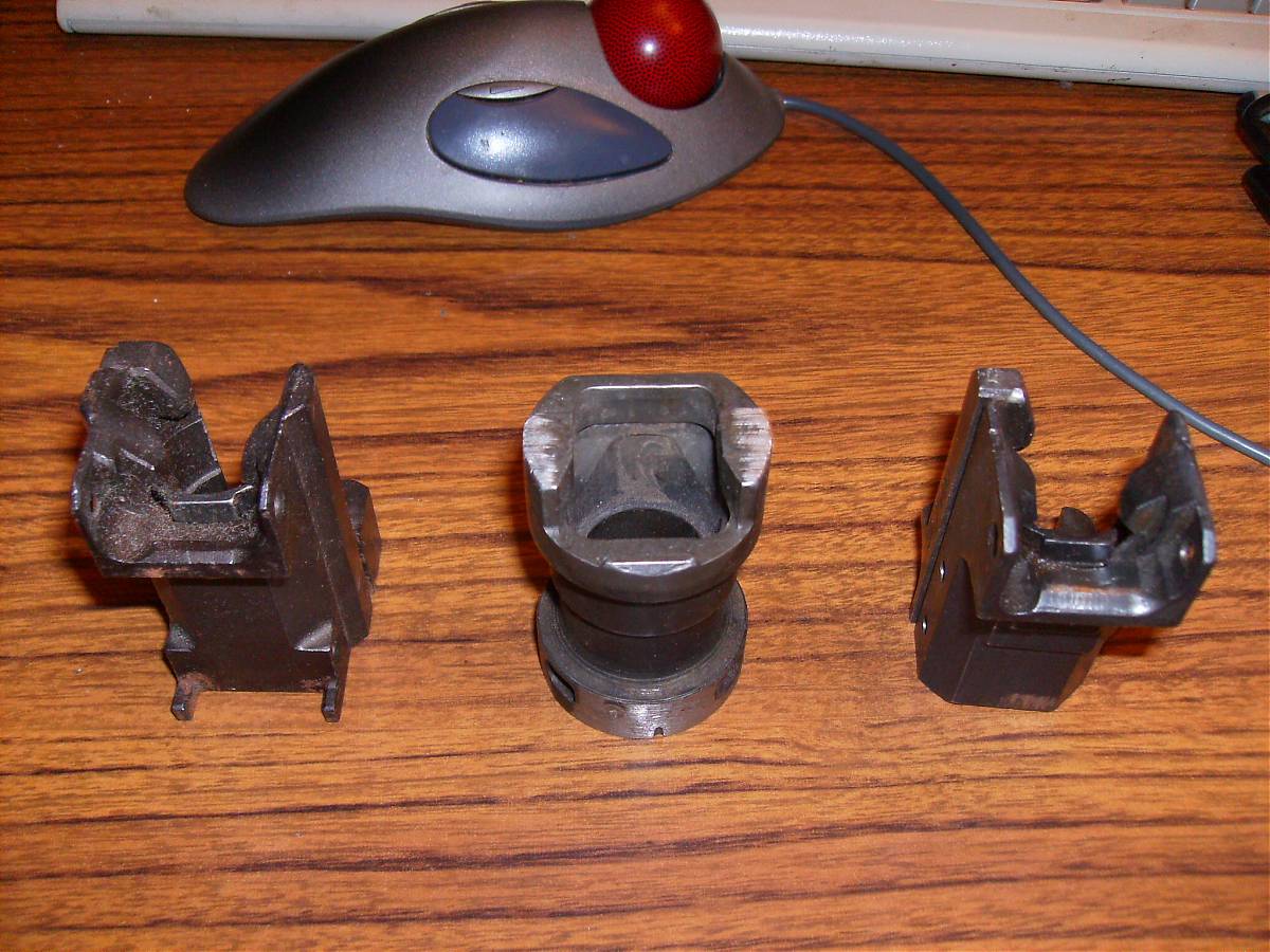
Yugo, G3, Romanian trunnions compared.
TRX
10-13-2010
Figuring up the width of the rollers, bolt carrier, locking piece, and a
reasonable amount of metal around the trunnion to hold the rollers, the width
of the trunnion comes out to... the same as an AK. My local steel supplier
doesn't have any in stock, but they did have the right size for making the
locking piece. I'll order from 1-1/4 square 4140 from MSC in a week or two.
I can't allocate any big blocks of time to work on it, but I can slipstream a few bits in here and here...
TRX
10-14-2010
Picked up some square 4140 for the locking piece today. The 8mm reamer and the
4140 for the bolt sleeve showed up. I also ordered a 10-pack of Bren mags,
some G3 rollers, and a G3 roller retainer from Centerfire a few minutes ago.
Yesterday I started making a bushing for the barrel vise so I can get the barrel off my stalled .45-70 Enfield project. The barrel, which is in very good shape, will go on the roller locker. It's already chambered and in good shape, I have .303 brass and .311 bullets on hand, the magazines are only $3 each, and the squirrels thought a scratchbuilt roller locking semiauto in .303 British was way cool.
TRX
10-15-2010
I picked up some 1-1/4 hot rolled square bar today, for the bending fixture
and to machine a test trunnion and bolt from before working with the expensive
stuff.
I have some ordinary .040 1018 sheet out in the shop; I'll use that for the test receiver. I have some .040 stainless, but that stuff is a b*tch to cut. Hmm, I wonder how one of those abrasive blades would work in the circular saw...
Dimensioning the receiver and trigger housing has to wait until the magazines get here. I could make a guess and add a little, but other than enthusiasm there's no reason not to wait.
What I've come up with is a 1-1/4 square receiver with an open top, sort of like an AK, except with the barrel centerline on the centerline of the receiver. An AK-style gas setup on top, but the magwell, trigger housing, and grip mount on a separate piece bolted to the bottom of the receiver.
I *think* I have the ejector sorted out; at least, I haven't had any new ideas in the last few days.
I have a spiral notepad by the bed, one in the Throne Room, and one out in the workshop, all filled with design scribbles...
TRX
10-15-2010
Can someone check my work here?
.460" .303 case head diameter (.23" radius)
49,000 PSI SAAMI pressure
area formula: area = pi * radius^2
r^2 = .23 * .23 * 3.14 = .166 sq. in.
since our unit of pressure is "per square inch", we just multiply 49,000 by .156 of a square inch to get 8134 pounds of case head thrust
That comes out to about 4070 pounds per roller.
I think I just had a "come to Jesus" moment with regard to proper heat
treating... and that's line contact, not nice flat bearing areas like a
turnbolt.
Well, that's why I'm making a very simple bolt and receiver for test-to- destruction. And I'm damned glad I own a Magnaflux rig!
TRX
10-15-2010
Hmm... doing some web searching, the Alemite model 500 lever operated grease
gun is supposed to generate 10,000 PSI and costs less than thirty bucks.
I have a 30,000 PSI hydraulic gauge around here somewhere; it should be easy enough to see how much pressure my 30-year-old no-name grease gun puts out.
The gun will also pump ordinary motor oil; I've used it that way for older British cars that recommended that.
edit: 49,000 pounds per square inch of pressure, .166 square inches to get 8134 pounds of thrust. I need 49,000 pounds to duplicate that, not 10,000. "Duh."
Hm, I could use a cheap hydraulic cylinder from Surplus Center, rig the barrel stub to it, and use it as a force multiplier for a grease gun. Let me find that catalog...
TRX
10-19-2010
Solved:
extractor: AK type notched round bar, pivot pin at back, round wire spring around bolt nose
ejector: slot in bolt nose, hinged and sprung tab to rise up when bolt moves past magwell, get pushed back down by bolt when it slides forward. Similar to a Mosin ejector.
trigger group: I spent a couple of days working out two different low-profile setups. One uses a semiauto MAC style "hog ring" hammer and sear plate. The other uses a striker and more conventional trigger. All the easy designs are full auto; making it semi takes more bits and work.
bolt and locking piece: sorted out, with the various cuts for the extractor and ejector, the firing pin, retainer screws to keep it together, etc. Now I understand why bolts get so complex.
Now for the parts I'm still fighting:
The Bren magazines came in today. I'd been using a flat-bottomed bolt design, but I had to redraw the bottom of the bolt and part of the receiver to put a "foot" on the bottom of the bolt to allow the Bren mag to sit as high as possible, so the "foot" could strip off a cartridge. It still sits lower than the mag in an AK; it can't go any higher without running into the rollers.
The bolt nose is quite long to get in all the bits. The bolt recess in the trunnion has to match - it's 1-3/4" deep from the back of the barrel to the back of the trunnion, and chock full of bolt bits. There's not really any practical way to make it any shorter.
The problem is, the Bren mag feed lips are about 1-1/4" long. That means the cartridge will be "free" anywhere from 1/2" to 3/4" of the bolt travel before the point of the bullet actually enters the chamber. I figure the cartridge is just as likely to jam the point in the corner between the barrel and inside of the trunnion for a thermonuclear wedgie as it is to actually go into the chamber. It might feed, but I put no faith in that.
Looking at the G3 trunnion and mag I ran into, it looks like H&K ran into similar problems. They actually cut the bottom of the trunnion out all the way to the roller centerline to move the magazine as far forward as possible. That means the back edges of the roller troughs are only fully supported at the top; the bottom is just in bending. I think I'm looking at one of the reasons the development of the G3 took years, and still needed some serious steel and heat treating.
I could shorten the bolt nose maybe 1/8 inch if I went to a sliding block extractor. I might get another 3/16" if I move the lug on the magazine down so the mag can sit farther forward. I might be able to extend the feed lips of the magazine forward a bit. But I'd really like to avoid modifying the magazines if I can.
I picked up a PSL magazine with the Brens. I stuffed a couple of 54Rs up to it and checked it with a Yugo trunnion. The Yugo trunnion is much shallower than the roller design, of course, and the nose of the bullet is well into the chamber before the rim pops out of the feed lips.
Just think, when I started this all I was worried about were the trunnion, rollers, and bolt...
TRX
11-10-2010
Weapons Guild has been running a "Homebuilt Challenge" competition for the
last couple of years. Three weeks ago, in a moment of enthusiasm, I signed on
to build a roller-locked rifle.
The design is a long straight box, like a PSL receiver except a straight tube. There's a bolt-on lower to hold the magwell, trigger group, and pistol grip. Caliber is .303 British, with Bren magazines. I'm whittling chunks of 4140 into gun parts.
In lieu of meaningful calculation on the locking mechanism, I'm building several trunnions and test receivers. I will then test them by standing off, pulling on a long string, and seeing if they blow up. Simpler than stress analysis, and vastly more entertaining.
The magazine, barrel, and two G3 locking rollers are surplus; other than some screws and springs, everything else will be scratchbuilt.
So far I've learned a *lot* about magazines, feed ramps, triggers, and extractors that I thought I knew before, but there's always that gap between knowledge and practice...
TRX
11-11-2010
Another "learning experience":
Cartridges that are physically very similar may still not feed from a different magazine...
I can get about five rounds of 7.62x54R (what I had on hand) into a Bren magazine by depressing the follower and sliding the cartridges in from the front.
Last night I tried a mag with real .303 brass. You just push down from the top and they snap into place.
The cartridges are very close in size. In magazine lips, the tiny differences count...
TRX
11-11-2010
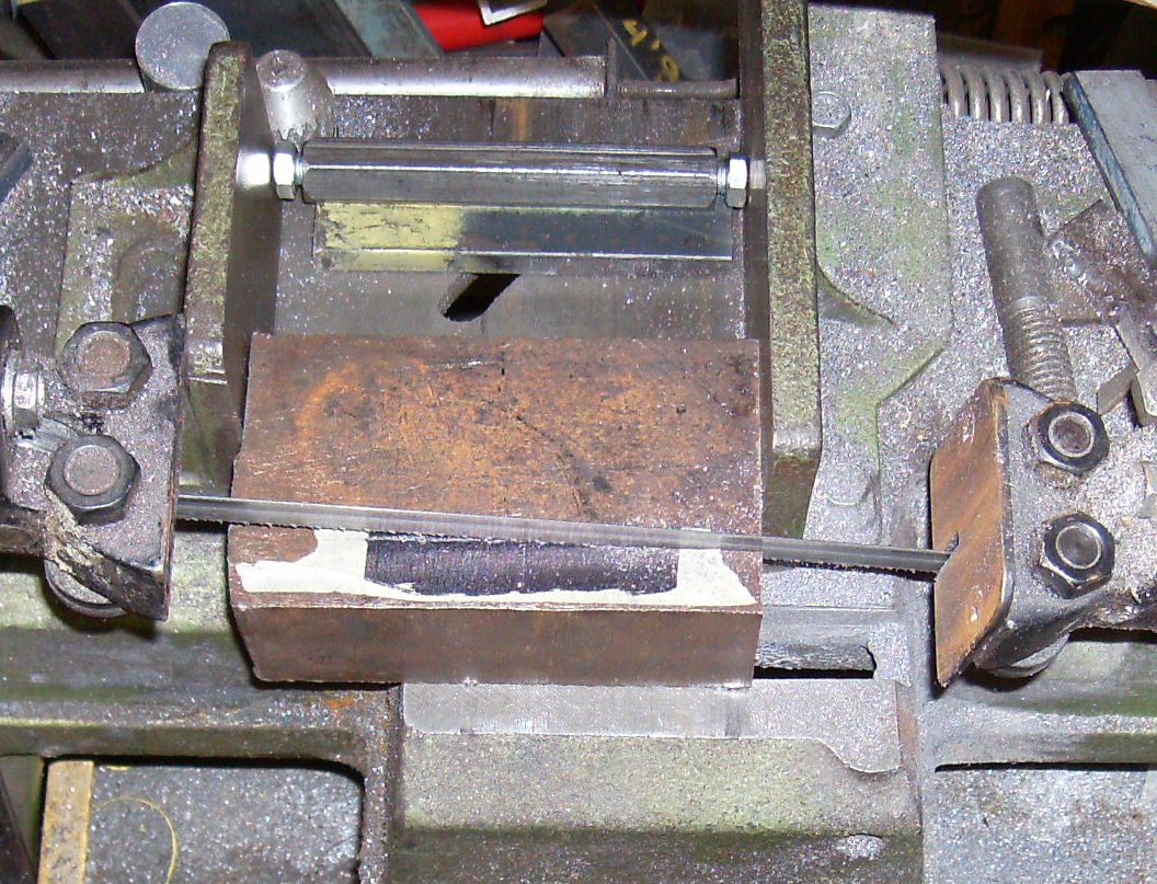
1) sawing a random block of steel for the bending fixture spacers.
2) flycutting the thing
3) finishing the spacers
4) cutting some hot-rolled 1-1/4 bar for a test trunnion
5) a "feed and fire" flat to bend in my AK bending fixture. It's too short for the real thing, but it saved metal and time
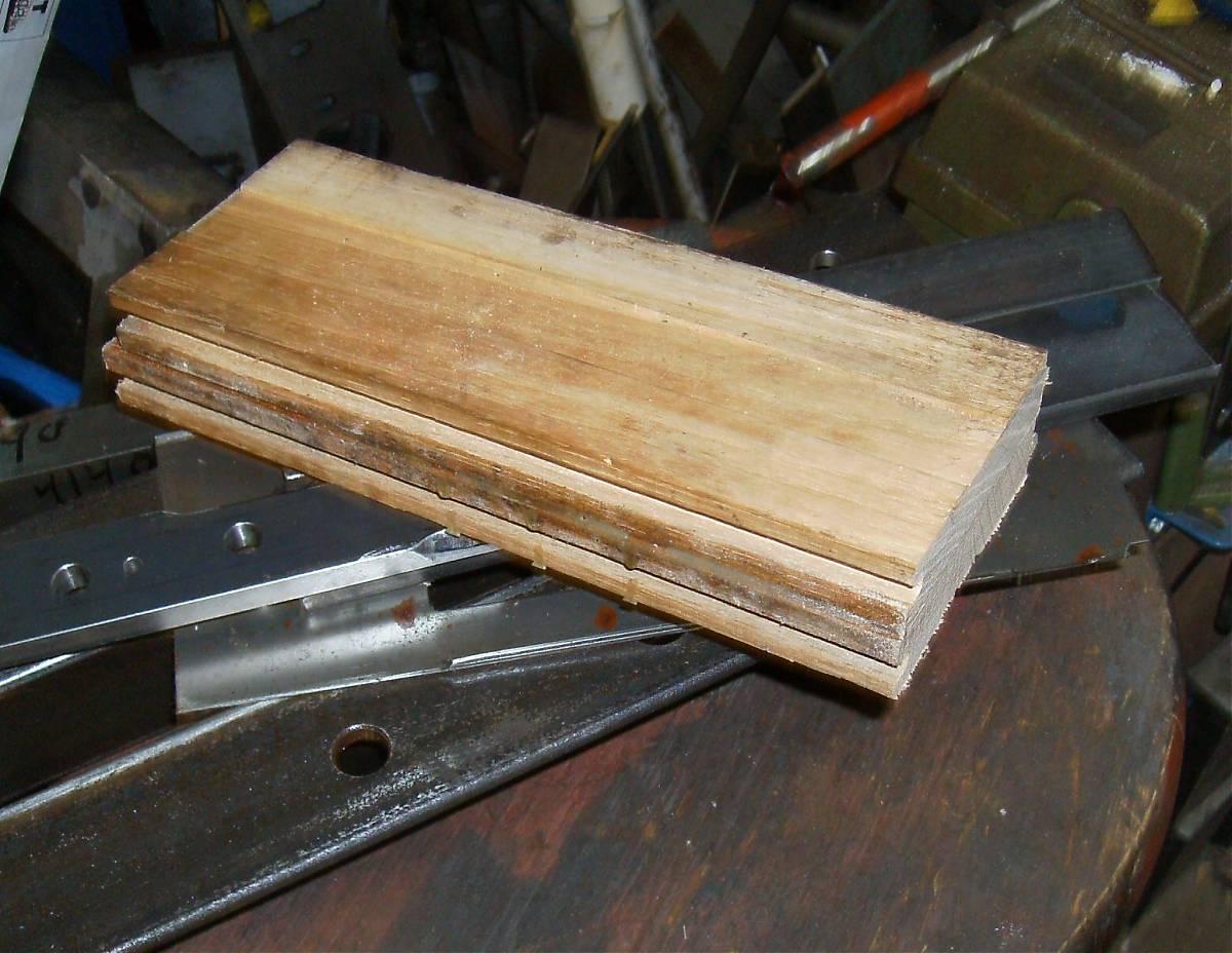
6) what to do with 60-year-old red oak flooring? Besides feeding the burn barrel, I glued a couple of pieces together to make the pistol grip. If I can borrow my Dad's planer I may make the foregrip from this stuff too.
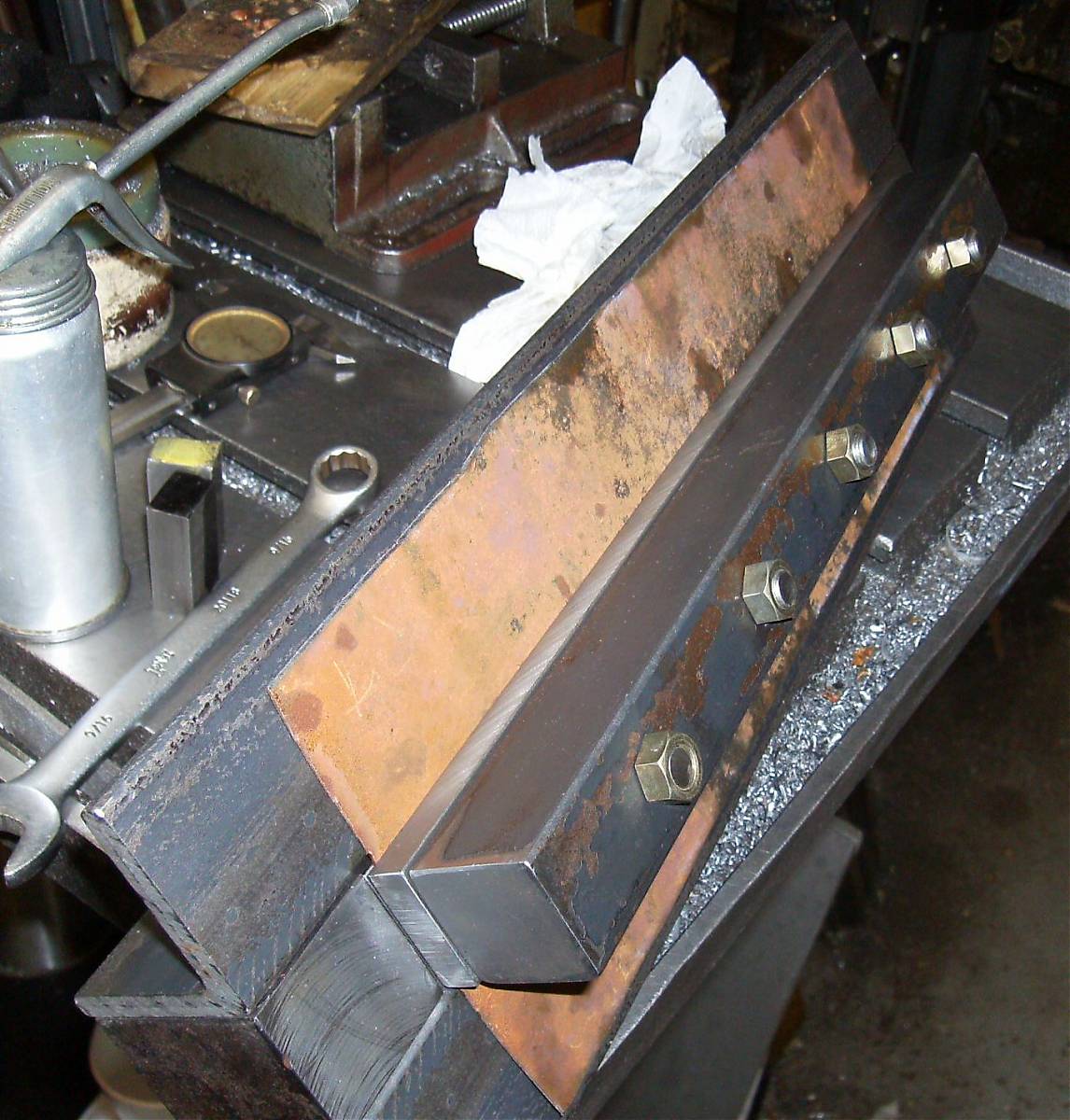
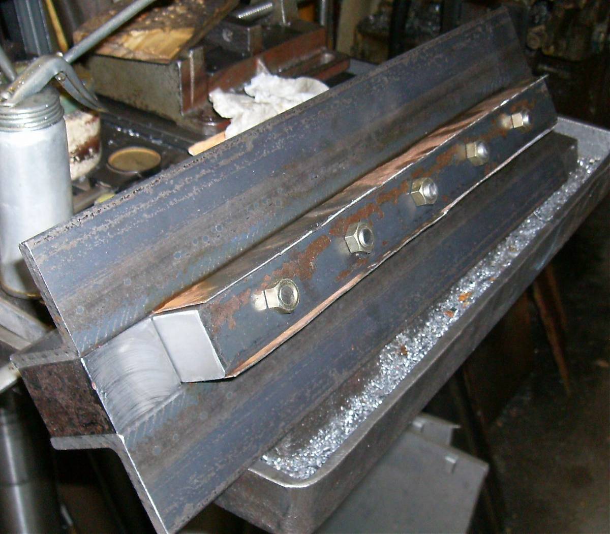
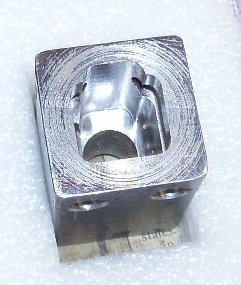
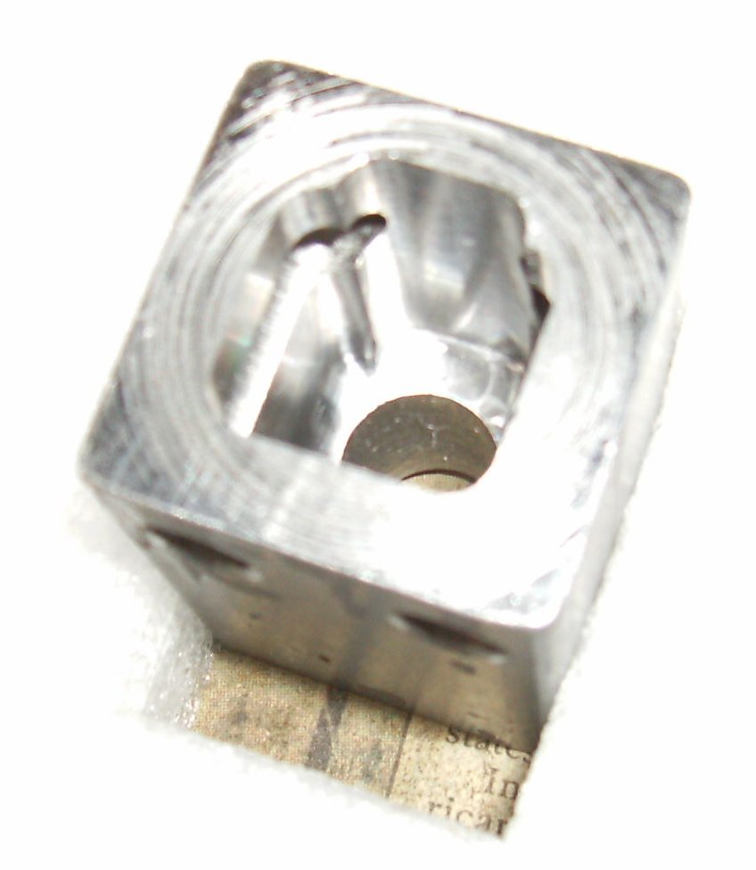
![]()
![]()
![]()
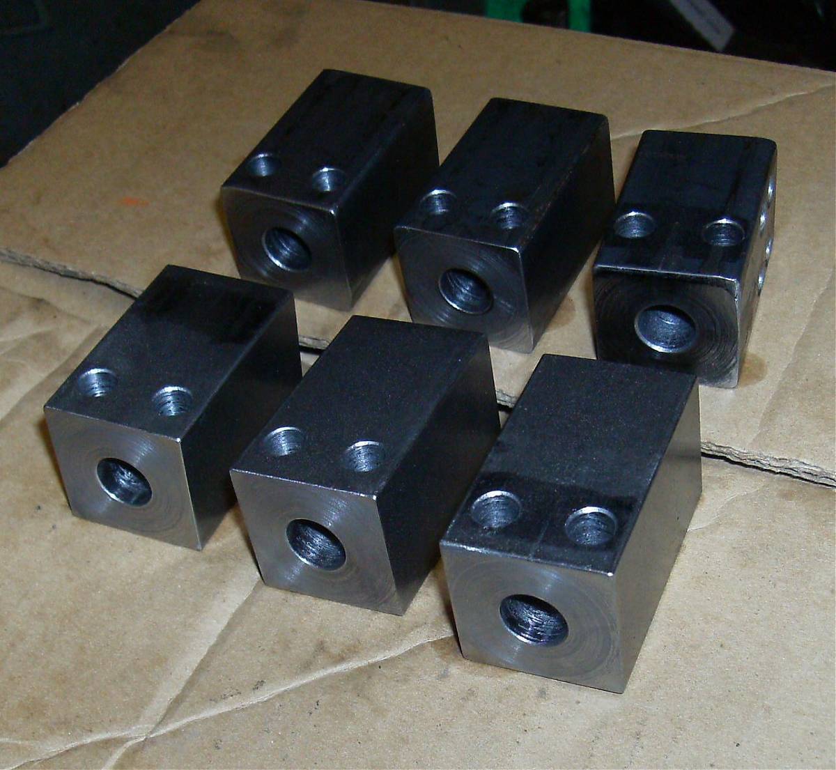
Three hot rolled trunnions for practice - notice one has been practiced on already - and three 4140 for the real deal.
13" bending fixture. I decided to leave plenty of room for the .303 cartridge, magazine, and bolt overtravel. I can always make shorter receivers in it if I want.
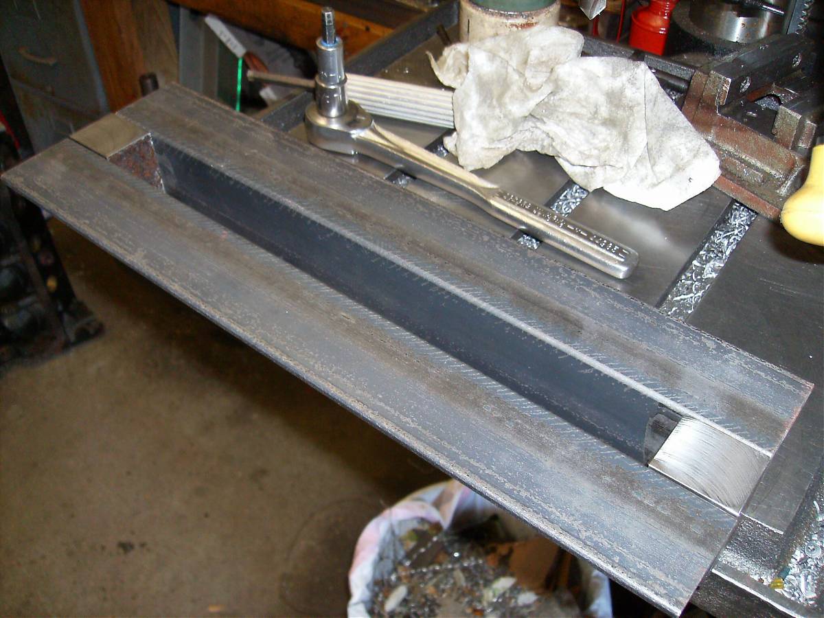
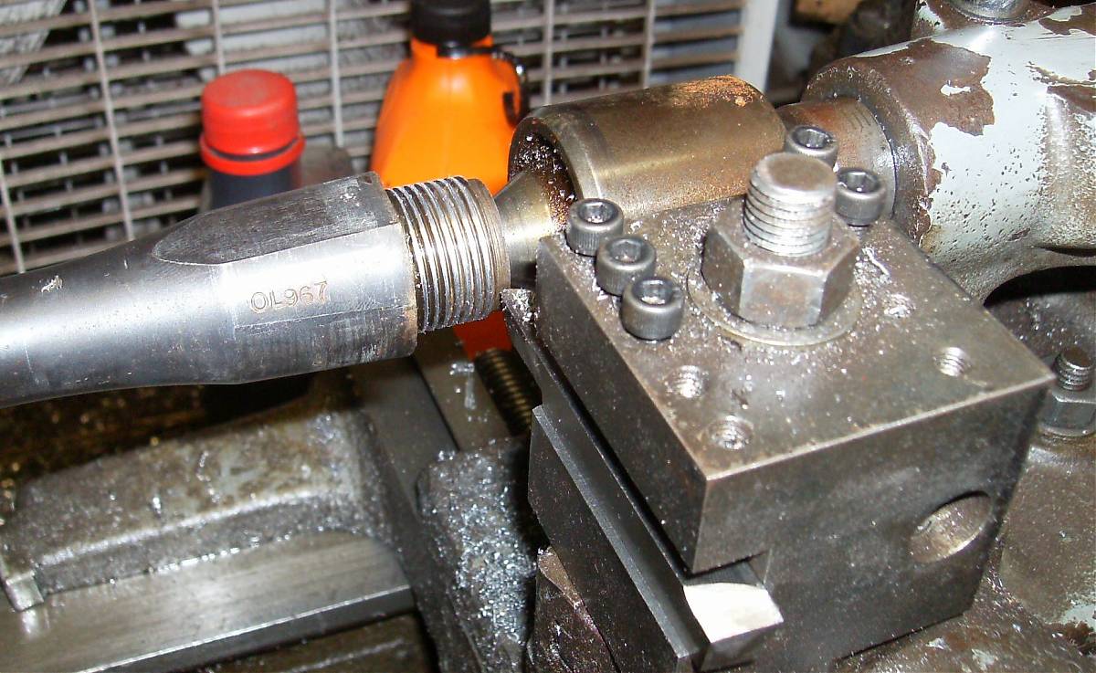
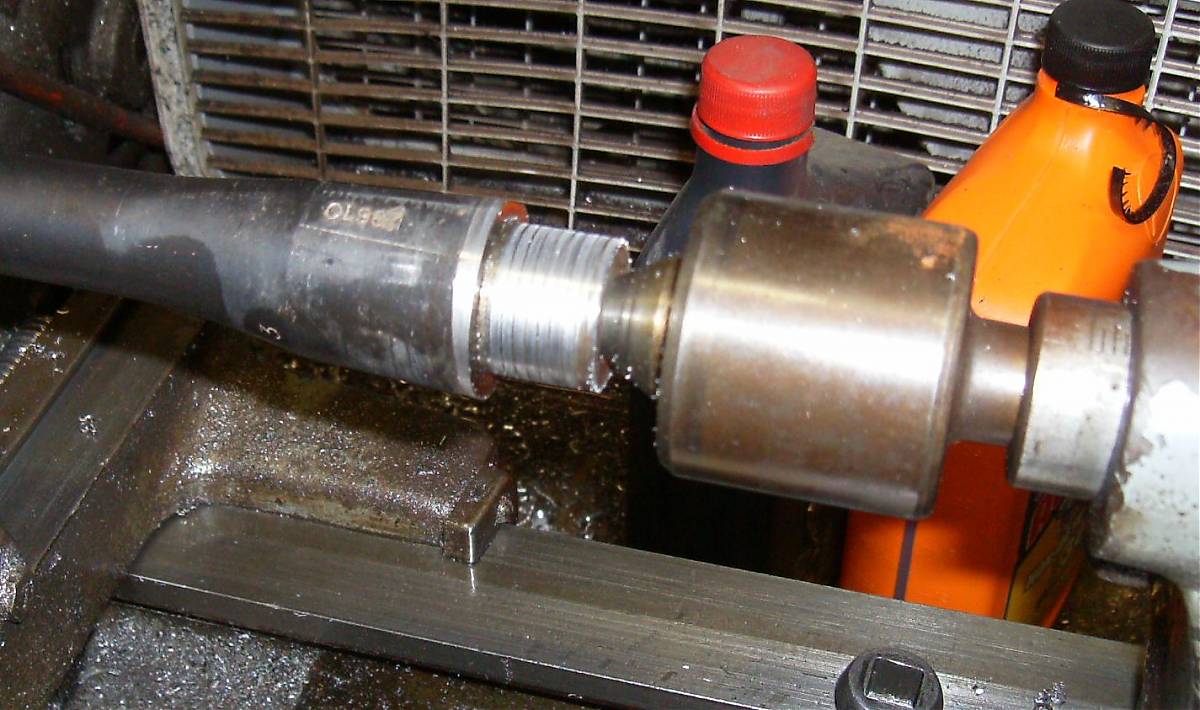
I turned the threads off the Enfield barrel and bored the junk trunnion to fit. The minor diameter was so close to the AK .908" diameter I just stopped there even though a few more thousandths would have slicked it up.
The fat part of the barrel was 1.305" and the trunnion is 1.25", so I cut it a bit. It not only had the "Knox form" cut on the top, it wasn't completely round. Long Branch may have forged the shape instead of cutting it on a lathe.
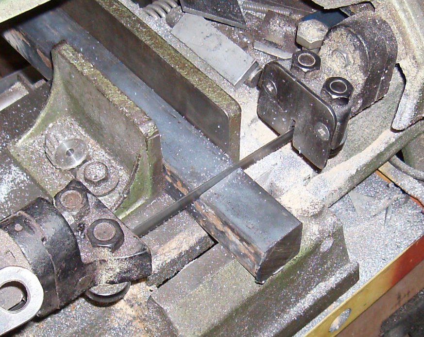
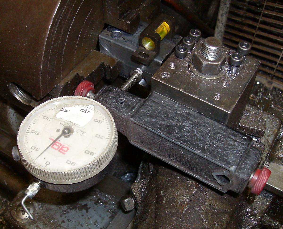
Centering a square part takes a little more work than a round part. I used an old dial indicator with an extra spring since it was getting a bit sticky in its old age, and a couple of drops of synthetic oil didn't help much. The weird thingie at the top is one of the test probes I got in a kit full of indicator accessories I bought years ago; this is the first time I had a use for it, even if it's probably not exactly what the manufacturer intended...
The level is so the part is straight up when I'm moving it back and forth. When I asked about centering square parts on one of the machining forums several people told me that doing it by eye was close enough. (I'd only used collets before) It turned out their idea of "close enough" and mine wasn't the same; without the level, I couldnt' repeat figures within .010". With the level, I got it within .001" T.I.R. Maybe Real Machinists don't need levels...
TRX
01-24-2011
That's one reason I made the trunnion the same width as an AK. Bend a
receiver, make a Molot-type top cover with simple straight bends instead of
the AK's complex curves, make the rear trunnion and recoil spring carrier.
I'll be putting up pictures of those when I get them built - simpler and
easier to make than the AK layout.
The main difference between the Imperial Battle Rifle and an AK-47 is that an AK has the barrel centerline raised almost to the top rails, with the top of the barrel and trunnion hanging out of the top. This puts a stout bending load across the receiver when the rifle is fired, but you get room for the trigger group, plenty of clearance for ejection, etc. The IBR's barrel is on the receiver centerline. This reduces the bending load, which probably isn't much of an issue anyway, and requires a separate trigger housing and makes ejection more complex. For example, I can't eject directly to the side since the extractor and roller want to occupy the same place on the bolt head.
Mostly, I went to the on-center barrel and separate trigger housing/magwell because I didn't want people to look at it and say, "oh, you built a PSL in .303. I've seen that before."
In other news, a bag of parts showed up Friday. I have a CAR-15 mainspring, a standard-length AR gas tube, an AR gas key, and an AR charging handle for the IBR.
I don't remember if I mentioned that I'm building this with a Stoner type direct impingement gas system instead of the Kalashnikov system. I'm not sure if I'll use the charging handle, but I've never liked a reciprocating bolt handle.
TRX
01-24-2011
TRX Builds the Imperial Battle Rifle
[from the build thread at WG]
I've been sketching a roller-locked rifle design since about the time the Challenge opened. I'd thought about actually building it and joining the Challenge, but I'm well aware of the amount of work involved, and time is already short. I was thinking about building something else - I've had a bullpup carbine with a Calico helical mag sketched out for some time now - and had was thinking about building that.
I was mentioning this casually to my wife. Her reaction was, "well, turn off the computer and get your A$$ out to the shop and do it!"
So, to maintain marital peace and harmony, I'm doing it.
She'll never know how close I came to naming it the Wifebeater Special...
As with many projects, this one keys off parts that were laying around. In
this case, I had a good Enfield SMLE barrel on hand. In the Challenge's
spirit of wacky craziness, why not scratchbuild a roller locking semiauto in
.303 British? And 10-packs of Bren mags from Centerfire sell for $30.
In the interest of building this thing within the 69 days left to me, I've had to make a number of decisions based on cheapness and speed. I looked hard at various tube layouts, but it looked like it might be easier (not necessarily better, just simpler and faster) to build a square action than a round one. Turn the tube into an open box, and you have your basic Kalashnikov layout. Putting all the locking bits in a separate front trunnion also helps a lot. I'm also more familiar with AKs than anything else, though not one single part will come from or fit an AK.
The mathematical stress analysis of the roller trunnion is beyond my skills. The rollers act as a wedge multiplying the thrust load from the case head, and then there's the problem of figuring hoop stress with a square hoop... you can only waste so much time contemplating this sort of thing before you say "screw it".
I ordered enough 4140 square bar to make several trunnions, and I have enough material to build several simplified test actions. Why dink around with calculations when you can just blow stuff up?
I'm sure material selection and heat treat will play a big part on how well this works. I know it's doable - there have been roller locked (as opposed to roller delayed) rifles before. Whether I get a useable trunnion in the amount of time I have to experiment with will depend on luck. But even if I fail, I can provide spectacular video and pictures of destroyed pieces. Some people would think that's even more fun than a functioning rifle...
Finished barrel vise. Made AK bushing (to remove barrel from milled Chinese receiver, for use according to rules). Made bushing to remove SMLE barrel from Lithgow receiver. Got .040 CRS sheet for test receiver, sheared and deburred a 4-5/8x10 piece. Sawed off two pieces of 1-1/4 CRS for dummy front trunnions for function testing. 1-1/4 4140 showed up from McMaster-Carr.
---------
Right now I'm building a simplified, non-firing testbed to verify the bolt- magazine-trunnion feed geometry. There's a big square hole in the trunnion for the big square bolt head required by the roller setup. The rollers limit how high the magazine can ride, which means the cartridges have to bump up and over the bottom the the trunnion on their way to the chamber. The feed path doesn't exactly give me a warm fuzzy, so I want to make sure it will work before I cut metal for real.
The CETME magazine sits closer to the barrel centerline, the cartridges are rimless and sit higher in the magazine, and the magazine is farther forward, so the nose of the bullet is entering the chamber by the time the rim pops off the feed lips. To get the magazine forward they cut away the bottom of the trunnion, so the bottoms of the rollers are riding in "wings" that aren't well supported. They make it work by fancy metallurgy and heat treating. I'm supporting the roller fully, top and bottom, and the feed lips on the Bren magazine aren't long enough to hold the cartridge until the bullet enters the chamber.
I'm going to see if I can make it work with the standard Bren magazines first. If I can't, I'll try extending the feed lips. My attempts at welding or brazing sheet metal usually turn out ugly, so I'm going to avoid it if possible.
Picked up some 1" square HRS for the handles for the action wrenches so I can get the .303 and AK barrels loose. Ordered a bunch of new cutters and other tooling for the build. Also ordered some O1 drill rod for the firing pin and some other pins.
I started with a 13/16" square bolt in a 1-1/4" square trunnion. The barrel is centered in the trunnion, and along the centerline of the receiver, instead of being up near the top like a Kalashnikov. More on that later.
My scaled drawings showed problems with the Bren magazines and the breech. To clear the bolt, the magazine had to sit fairly low. Problem Number One was that when I laid a magazine down on the scale drawing and pushed a cartridge out, there was about half an inch of free play between leaving the magazine and the bullet entering the chamber. I know some designs leave the cartridge free for a moment, but due to the mismatch between the squared bolt opening and the round barrel, there were places where the point of the bullet might go and jam the mechanism. Murphy's Law says this will happen a majority of the time. The problem was aggravated by the low height of the magazine, which fed the cartridge up at a sharp angle, almost guaranteeing a jam.
Most other roller designs let the rollers slam against the firing pin when the breech unlocks. I'd thought that was bad design, and had added a short nose on the front of the locking piece, where the rollers would rise the nose instead of the pin. Getting rid of the nose and changing the ramp angle shortened the breech depth almost 3/8".
My desire to use unmodified Bren magazines had led me to set the magazine back slightly. I sucked it up and drew a small notch in the bottom of the trunnion to clear the mag latch. This let me move the magazine all the way up against the breech, closing the feed distance another 1/8".
Along with this, I realized the flat-bottomed bolt couldn't strip a cartridge off the magazine. The double-stack mag lips wrap around the tops of the cartridges to hold them in place; the bolt has to drop down and sweep *through* the top of the magazine instead of over it. A single-stack mag can have the top of the rim sticking above the mag and doesn't need a bolt slot.
If you look at an AK bolt you'll see the bolt is notched deeply on each side to clear the top of the magazine. And somehow I'd never noticed until I ran a straightedge across the firing pin hole... the "foot" on the bolt is so deep they moved the locking lugs up so high the bottoms are just barely below the centerline of the bolt.
Generally, it seems single-stack mags can feed from a plain bolt, and double- stackers need a foot. Of course one exception popped up immediately - the Enfield SMLE, which uses a plain round bolt and a double stack magazine. On closer inspection, the receiver forms the top of the magazine, and pinches the cartridges to almost a single-stack width.
Now I know why the CETME rollers are only 3/8" high - they either had to drop a foot down into the magazine and possibly have feed problems due to the angle of the cartridge, or they had to run a short roller and cut the bolt as high as possible to wrap the top of the magazine around the bottom of the bolt.
I made the bolt slightly rectangular, then cut notches along the sides, with just enough metal to keep the rollers from falling out. The extra depth required even relief in the trunnion.
A couple of pictures and a few lines of explanation somewhere would have saved two days of chasing my tail...
The receiver has to be long enough for all the parts, plus overtravel for the bolt. Theoretically the cartridges are uniform enough that the bolt just clears the back of the magazine before it comes forward again. In practice, variations in ammunition (and temperature!) mean the travel can vary quite a bit.
If you go to YouTube you can find several high-speed videos of AKs firing with the top cover off, so you can see the bolt travel. From the same magazine, the bolt ranges from just barely stripping the next round to slamming against the rear trunnion.
The AK has about 1-5/8" of overtravel. I decided arbitrarily to go for 1- 3/4".
Okay, the front trunnion is 2" long. The Bren mags are 3-1/2". The bolt nose is 1-1/4", plus the bolt has to be at least the length of the magazine, make that 4-3/4", plus 1-3/4" overtravel, plus the thickness of the rear trunnion, call it 13".
You have the accomodate the magazine, and the bolt has to cover the magazine, so the receiver length changes for 2x for every 1x of magazine length.
Once you know where the back of the bolt is, you can position the sear or hammer. With the locking piece only 1/2" square, doing a striker is more fiddly work than I feel like taking on, so I'll be going with a hammer.
Generally you want the overall length of the rifle no longer than necessary, so figuring some space for the mag latch and trigger guard you get the position of the pistol grip. This then lets you pick the length of the stock.
Having gorilla-length arms, I'd always liked a long reach. But after a few AKs I realized the advantages of a short stock; the extra bend in the elbow didn't bother me, and the shorter rifle's weight has less leverage against my aging shoulder when I hold it up. So I'm moving the grip forward and using a short stock.
With these parameters set, I can lay out the trigger group and mag release, and make some sketches of what it may look like when finished.
The Bren magazines are superficially similar to AK magazines. They have a brazed-on locking lug at the top front, and a triangular locking ridge across the back. It looks like the locking ridge was welded and ground to shape.
Due to the locking lugs, the Bren mag needs to be rocked-and-locked into position like an AK. Since this design has the barrel on the receiver centerline, there are no dimples to keep it from flapping around. No problemo, the bolt-on trigger housing under the receiver incorporates a magwell to stabilize the mag.
Moving the magazine across the full-scale drawing showed the magwell wouldn't work; a magwell wants a magazine that slides straight up and locks, like an AR or G3. This means the front of the magwell has to be cut away to allow the magazine to be rocked into place... but the Bren magazine is tapered; .950 in the front, 1.11 in the back. The taper interferes with the rock. We only need to stabilize the sides *somewhere*; a quarter-inch strip on each side at the back would do... except the front bolt of the trigger housing/magwell is ahead of the magazine, and needs some support. I think I've come up with a cutaway shape that will work; I might also bend the front edges of the magwell out a hair if needed.
PSL magazines are even more tapered, but they have enough clearance in the hole in the bottom of the receiver, and since the trunnion rides high in the receiver, there's room for stabilizing dimples in the receiver itself.
This leaves the latch mechanism. I know the Bren magazines mount upside- down, which probably accounts for the tiny locking ridge at the back. If you look at an AK or PSL magazine it has a large machined spur at the back, with a top taper that pushes the latch away, and a bottom taper that the latch cams into, using the latch spring to solidly press the magazine up into the rifle and hold it steady. By comparison, the tiny ridge on the Bren magazine is probably just enough to keep them from falling out during operation.
The tiny ridge on the Bren means the mag latch will have to be precisely located with regard to the front lug socket. [grabs calipers] We're talking about a triangular hump only .060" high. Since it's more or less an equilateral triangle, you could probably rock the magazine out even if there was a stout spring on the latch. Heck, I'd worry about recoil letting the mag come loose. "Bang... clank. Oops."
I'm letting this problem ride for the moment. If inspiration doesn't hit, this is the point where I'd give serious consideration to Dremeling a shallow slot under the locking hump, to give the latch something solid to bite into.
Making the wild assumption that I'll achieve a combination of material and heat treat that will stay together, I'd like it to actually feed cartridges from the magazine and extract the spent ones. Well, without ejecting the bolt carrier, top cover, and pieces of trunnion along with it. Though I'm sure it'd be just as entertaining, I *do* want to eventually wind up with a rifle that stays mostly in one piece when fired...
The main parts for the bending jig are sawn out, the spacer blocks are in the mill, ready to be flycut.
Vise bushings to remove the Enfield and AK barrels are finished. Barrel vise is finished and mounted to the mill table. AK receiver wrench is finished. I need to make one for the Enfield.
Redesign of the bolt and locking piece means I'll have to order some more 4140 tomorrow. I got the last bits from McMaster-Carr; I'll check Aircraft Spruce's prices before I order.
The sketches look much nicer with a wood stock, but for rules compliance I'll be using the AK barrel as the upper section of a skeleton stock. I thought about making it a sidefolder, but since I started late and time is a problem, I'll just make it a fixed stock for now.
Pictures are in the camera. Drawings will have to wait until I can scan them, which requires setting up a Windows box, since the only scanner I have is a winScanner, but at least it was free...
Spent all day out in the shop, most of it on the mill, flycutting pieces of steel for the trunnions, bending fixture, etc. Got the main blocks cut for the SMLE receiver wrench, made a trip to the hardware store for some 1/2" fine thread bolts for it, and measured the No.4 receiver I was going to take the barrel from; 1.305". On a whim I checked the No.1 receiver; 1.260". WTF? I think I'll just cut the hole at 1.305" and make an aluminum bushing for the other one. Also got a piece of 1/4x3" CRS cut to make the welding jig for the trigger housing/magwell weldment. It didn't have to be 3" wide, but I was recycling some previously-used steel.
Next step is to drill the front trunnion blocks and ream to 8mm. I checked the drill press alignment this morning, with a bar and an angle. Close to perfect. I keep drilling parts crooked; I suspect the trouble is the drill press vise. I'll have to check that before I use it again - it might have a hot date with the flycutter.
The reamer speed should be somewhere between 100 and 200 RPM depending on what references I use. The lowest speed on the drill press is 367 RPM; I've already run into that problem before, burning up >3/4" bits. Then I got a bright idea - the lathe will go down as low as 60 RPM in back gear. I'll find the speed closest to 100, put the reamer in a collet, and push the trunnion into it with the boring bar holder on the carriage. The boring bar holder has a 1/2" hole that will easily clear the 8mm reamer.
It's not quite mondo lathe fangleage like Zebdeming does, but I was glad I thought of it anyway...
I sawed two pieces of hot-rolled square bar for the feed-and-fit test trunnions, and three pieces of 4140 for the real ones. I have enough 4140 for a couple more if I need them.
Looking at one of the blocks and the drawing, it occurred to me that the only place that needed to be hardened was where the rollers actually set. For a "real production gun", this would be a perfect application for induction heating... the wear areas could be hardened while the rest of the trunnion remained ductile. Unfortunately out of my skillset and budget, at least within the time limit.
Also sawed out a piece for the rear trunnion, and a spare. Worked on the trigger housing jig. Didn't actually finish anything, but a bunch of little things lurched forward a baby step or two.
I don't think I'm dawdling, but it seems like it takes me a ridiculous amount of time to accomplish things. And other than cutting out the blocks for the trunnions, all I've done is make tools!
These pathetic progress reports are just to show I'm still working on it.
Also got a block of 1-1/2" square cold-rolled to make a hammerform for the top cover. I looked at making a bending fixture, then at buying one of the cheap Harbor Freight fixtures, then at a book I had on metalworking. According to the book this is a job for a hammerform. So now I get to shape a big piece of steel into the shape of the part I need, -.040" for metal thickness. Which will involve MORE! flycutting...
In good news, I finally got things finalized enough to lay out the magazine release and trigger group area precisely, as opposed to "somewhere in this general area." There's room for an AK-47 hammer and trigger if I narrow the hammer a bit. That will save a bunch of machining, plus it's a known sear geometry; something that might have taking multiple tries to get right otherwise. I found an AK template showing the axis hole locations, which I'll verify with one of my bent receivers.
I went to Apex.com and ordered a PSL recoil spring assembly for $15, two FN49 sling swivels for $7.50 each, and a leather G3 sling for $5.
The original design had a slide-off gas block with a half-round axle and a flip lever; the gas block doubled as the lower handguard retainer. The new design uses a screw to hold the handguard, and the gas block and tube are both fixed. To clean the gas tube, a flip lever lets you rotate a plug at the forward end of the gas block, so you can run a brush through.
In trying to make a "military style" design I've been using the idea that any small part that can be removed during a field strip can be lost, and should therefore be avoided if possible. That was one of my "duh!" moments when looking at some military rifles, many of which I considered to be overly complex - the AK-47 handguard and gas tube retainers, for example, are just WTF?! compared to the rest of the design.
An SMLE rear sight won't fit on my top cover without hanging ridiculously far off the sides. I dug up the old article again, then ordered an AR sight set for $25. Also a couple of hammer springs while I was at it...
The link to the thread is: Receiver cover peep build tutorial
The first steps to making the trunnions involve sawing them off, facing them on the lathe, setting up on the mill, and drilling the two roller holes. I managed to destroy two pieces; I could usually get one hole, and then the other would be off .010 or more.
I spent several hours yesterday in cursing frustration, then decided to blame the machine. The dial on the X feed has always been hard to move, so I decided there might be a problem there. It took a bit to get the freakin' dial off, because some previous owner had lost the lock screw and substituted a cup point set screw, which had buggered the shaft. The entire assembly was packed as full of chips and lumpy grease as it could get. Looks like water had gotten in there somehow, too, since there were marks on the ground bearing races. But they cleaned up okay, and after half a can of carb cleaner and 100 PSI shop air went through the bearing race, the thrust bearings were all nice and shiny. I filed the scars off the shaft and made a run to pick up some dog nose set screws or fine-thread brass screws, but of course nothing like that is available locally. I picked up some 1/4-28 Allen screws. They should work okay after I grind the ends flat. Then I got side tracked on some other stuff, so that was it for the day.
Meanwhile, my firebricks for the heat treat oven showed up a couple of days ago, and Holescreek stepped in to get me some refractory cement to stick them together with. He bought a whole 50 pound bucket of the stuff, so if you're contemplating anything involving sticking firebricks together, PM him and he'd probably be glad to sell you a flat-rate box full of the stuff.
So far, I've built a barrel vise, two sets of barrel bushings, and two receiver wrenches so I can remove the barrels from the AK and the Enfield. I've built most of the bending fixture for the receiver. I've started two more fixtures - one is a plate for mounting a test receiver to, so I can check magazine retention and the trigger group geometry. The other is a piece of 1/4x4 CRS a foot long, with threaded holes to hold brackets to hold the trigger housing pieces.
In a real production design the trigger housing would be aluminum; a casting or CNC'd. I'm making it out of a dozen bits of steel, all of which have to be held in alignment while I MIG them together. Then I'll have to grind it until it doesn't look too bad, slap on some paint, and hope the ugly spots don't show up too much in the photos...
One short test receiver has been bent in my AK fixture; technically the test receiver is a tool. So the only "build" part I've managed so far has been to ruin a couple of trunnions and to saw out some bits for the trigger housing.
Hey, it *is* progress!
Parts update:
Bren magazine: $4
AR rear sight kit: $25
AR hammer spring: $2
G3 rollers: $8
PSL recoil spring: $15
(parts box, values to be assigned later)
AK hammer, trigger, sear
Enfield No.4 Mk1 barrel
AK barrel
I was wondering about how to drill the hole for the stock bolt. Dunlap's gunsmithing book suggest setting the stock up on the lathe carriage and feeding it into a bit in the headstock. Failing that, use a thicker stock, drill the hole in the drill press, and then center the stock on wherever the hole comes out.
Serendipitously (and how often do I get to use that word?) I saw a post on this very subject a few days ago on another forum. The building sawed his stock in half, used the router to cut half-round grooves in each half, then glued it back together. Well, duh! I guess it would make a sporting stockmaker throw up, but a glue line on a "military style" stock isn't going to hurt anything.
A day or so after that I found a good way to do the handguard. I'd more or less thought of doing the handguard Galil-style - a fat bottom that wraps up around the barrel and gas tube in a big "U", with the top open. Then I was looking for information on the SVD's gas system (it uses a spring-loaded pushrod instead of a rod on the end of the bolt carrier like the AK) and saw that the Chinese NDM-86 used a vertically-split handguard. That makes fabrication *way* easier, since I can use the router trick to make the channels for the barrel and gas tube. I plan to put some nutserts in one side and run countersunk screws into the other instead of the elaborate latch system those rifles use.
Now bear in mind I can handle sawing, routing, and laminating just fine, but shaping the outsides is well outside my usual skillset. I guess if it comes down to it I can make a steel skeleton stock and wrap some expanded metal around the front for a handguard...
Looks like I'll have to use the chuck and a 7.7mm drill to leave enough meat for the reamer.
Also ran into another interesting thing. I think I mentioned that I'm using
an AK trigger and hammer; I have several laying around after putting 922r
parts into rifles. All Romanian single-hook triggers. I brought one into the
house to eyeball, and I happened to have a double-hook Chinese trigger that
came out of a 1966 Chinese AK. The hammer bearing face of the hooks was about
.090" higher than the Romanian. That's a lot.
Back in the say people used to complain about the axis pin holes being out- of-place on various flats and templates. I don't have an exhaustive list of AK bits to compare, but I'm pretty sure swapping Romanian and old Chinese trigger bits around various receivers could cause some WTF? moments.
In other news, I may have access to a woodworking shop to do the wood parts
with. Due to complex family reasons, my Dad's shop is no longer available to
me, but it turns out a friend's father-in-law has one, with a planer, router
stand and bits, sanders, etc. I have a chop saw, circular saw, and bandsaw
here, but without the proper power tools I was looking at a snotload of
rasping and sanding.
The original plan was to use a basic AK system, with a long overhead piston and long travel gas system. But there's a major difference between, say, a PSL and the Imperial Battle Rifle - the IBR's barrel and trunnion are on the centerline of the receiver, while the PSL or AK have the barrel centerline near the top of the receiver. The main reason for that is to allow for ejection - the fat spring housing on the bolt carrier means the case has to exit mostly to the side. To facilitate that, Kalashnikov moved the entire trunnion up in the receiver, then twisted the locking lugs 45 degrees, moving the right-hand lug down so he could cut away the right side of the trunnion for ejection clearance.
The IBR uses a longer bolt travel than a PSL, and the cartridge has to come all the way out of the breech before it is ejected, instead of just out of the barrel, like an AK. The original plan was to cut a port in the side of the receiver and eject through that, with a spring-loaded door like an AR-15.
I ran into some problems with that early on; the rollers occupy the space where parts of the extractor and ejector would have to go. Lots of rifles cut into the locking lugs to provide the space, but I'm breaking enough new ground here, and I wanted solid metal between the breech face and the rollers. This meant the ejection path needed to be mostly up, say 1 o'clock. Which also meant the receiver would be stronger, since there would be no ejection port cut into it.
Unfortunately, the spring housing on the bolt carrier would foul the path of the cartridge. But the SVD and NDM-86 used a shorter spring that doesn't go out over the front of the bolt, and used a separate pushrod instead of a long gas piston on the front of the carrier.
This means the entire front of the carrier is clear when the bolt is back; the cartridge can be ejected straight up if needed. (not desired; hot brass down the back of your shirt is annoying) Done properly, you can shave some height off the top cover too. The Commies didn't bother, though. If you move the recoil spring down in line with the bolt and shove the extra length down into the stock instead of on top of the bolt, you could reduce the top cover height to 3/8" or so, moving the centerline of the gas system down that much closer to the barrel.
With that in mind, and looking for something else entirely, I just wound up looking at some M-16 bits again. The Stoner "direct impingement" system turns the gas piston into a nub on the end of the bolt that pilots into a gas tube. The tube is bent around through available space. It's lighter, has fewer pieces, and no moving parts. Cheaper, too. Downside, argued ferociously on various fora, is that the gas actuating the bolt carrier winds up inside the receiver.
This would surely be death with corrosive-primed Combloc ammo, but modern powders and noncorrosive primers mostly leave just soot. Which, though irritating, doesn't hurt anything much. I have photos of my MAC-11 SMG shooting fire out the ejection port while in rock-and-roll mode. There's still plenty of pressure in the barrel when the mouth of the case clears the breech, and all that gas goes... right into the receiver, same place as a Stoner gas tube.
The squirrels in my head have developed a sudden fondness for the Stoner system, and are now trying to persuade me to go that route. Their arguments are hard to refute. And there's always the problem of, though the IBR is an original design, to most people it will look like a mutant PSL, just like when I look at an FN-C and think "AK".
I've been stressing on how I might upscale the AR-15 gas system to work with a .303. Then I realized most of the work has already been done - a quick search showed the AR-10 also used the Stoner system, and was chambered in .308.
The roller lock will require almost no effort to unlock by comparison to a turnbolt setup... but the gas system still has to whack the bolt carrier hard enough to cycle it against a spring strong enough to strip the next cartridge off the magazine.
I could copy the AR-10 system, then use a needle valve or crimp the tube to reduce the impulse to the bolt carrier as needed.
According to a tech note on the Armalite web site, the AR-10 gas tube is the same as the M-16 tube, other than being .240" longer. In the parts section, the "M15" and AR-10 gas keys have the same part number. If these parts are the same, the main difference would be the hole for the gas port in the barrel. I'd guess the AR-10 recoil spring would be much more substantial than the M-16 spring; stripping .308s off an M-14 magazine such as later AR- 10s used puts a hurt on my thumb...
This indicates that, like the Kalashnikov, the Stoner design is also reasonably flexible. The main variables would seem to be the recoil spring and gas port.
The strength of the recoil spring is determined mainly by how much effort it takes to strip a cartridge out of the magazine; this can be considerable for the top cartridge in a full magazine, where magazine spring preload is highest.
I think I'll snag an AR-15 gas key and tube to take a look at.
Interestingly, according to the Armalite web site, the AR-10 does not include the forward assist for the bolt, and the side of the bolt carrier lacks the M- 16's ratchet teeth. The tech note said the assist was "not needed due to the stiffer recoil spring."
My wife opened the box and promptly appropriated the sling. The ad said it was used, but it looked new to me. For $5, I surely can't complain... I'll order another one next time I get something from Apex.
I need to pick up some angle iron for the heat treat oven. And someone posted a link over in the tool section to a DIY Rockwell checker - Ray Rogers Handcrafted Knives:Build Your Own Hardness Tester! It turns out I have every single piece needed to build it, other than the penetrator diamond, which I found on eBay for $65. I always wondered what I would use a 3" face, .250 travel, .0001" dial indicator for... that thing has been sitting in my toolbox since the 20th century. I did a bunch of web searching and found a few threads with people talking about the Rayvin DIY Rockwell checker, but nobody claimed to be working on, or to have finished, one. It's definitely not pretty, and it looks like it would take a little finesse to get repeatable results, but man, the price is right...
So, since I didn't want to just drill them out oversize (and follow the angle...) and I just happened to have a brand new 3/8" end mill, I could at least straighten them up. The extra slop in the end holes wouldn't hurt anything.
For most of that day, I searched for my 3/8" collet. Which I eventually found in a drawer, slid over my edge finder, instead of in the collet rack where it belonged. The shop fairies must have done it during the night, because I certainly know better...
It wasn't a total loss. During all the searching I managed to find all the parts to my MAC-11, which I'd taken apart last year. In my shop, some strange Brownian motion then proceeds to slowly migrate all the pieces of any assembly as far apart as possible, then burrow down under things to hide. A moment ago I put the whole gun back together. At least next time, I can misplace the whole thing instead of just parts of it.
2) tapping the bending shoe
3) full-length flats cut out
4) 3/4" tube cut and drilled for rear sight. Unfortunately, either the drawin on sksboards was wrong or I got weird parts, because the diameter of the small hole was way off. So I'll have to flip it over and start from the other end... that was just a piece of tubing from my junkbox.
I needed some 3/8" fine thread rod to finish the fixtures, so I went by Fastenal to get some. The counter dweeb pokes at the computer and says they don't carry such a thing... despite the fact they sold me some a few weeks ago. But they could order a piece in. Fine. $11.72, please. How does a $5.80 piece of rod turn into $11.72? They want to charge me shipping to move it from a store... that's in the next town. And they'd need three days to accomplish it, even though their truck runs twice a day. He seemed offended when I told him to forget it.
"Support your local business" my A$$. They deserve to die.
Hmm...
Fixture finished, two full-length receivers cut out and bent, trigger housing work... but too little, too late for the Challenge.
I guess it's time to make a graceful withdrawal. To be honest, I never expected to finish, but the entry gave me a lot of incentive to actually get my butt out into the shop and mutilate some metal instead of goofing off. The build will continue, with updates here or wherever the moderator decides is appropriate.
TRX
01-25-2011
Originally Posted by Viper Dude
For straighter drilled holes use a vertical mill starting with a center
drill then a fresh regular drill bit both held in a collet (vs a Jacobs
chuck).
Absolutely. But drilling a reasonably straight 3/8" hole through a 1-1/4 square bar shouldn't have any problems - and three out of five holes came out okay. The worst of the other two was probably .040 off when it came out the bottom. WTF?! No chips on the table, no dogging the bit through the metal, all five holes drilled the same way.
The problem happens from time to time; I ran into it on a couple of holes when I was making receiver wrenches, and spent some Dremel and file time straightening them out. Those were over 2" deep, but they're still shallow enough they shouldn't have had any drill wandering problems.
If it was a problem with the drill bits, all of the holes should have walked. I could understand that, and curse my tools or workmanship. Instead, I had a 2/5 failure rate and still don't know what to do to prevent it. Arrgh!
TRX
03-09-2011
The good new is, the guy who was machining the trunnions finished two, and
they're supposed to show up next week.
Also, Weapons Guild has a 2011 "No Holds Barred" Challenge going now, and the rules allow recycling incomplete projects, so I now have additional incentive to work on it.
TRX
6-12-2011
I bent four rest receivers from plain 1018 sheet. They're for function-testing
the design as far as stripping, feeding, ejecting, etc. Then I'm going to run
some live ammo through and see how many shots I get before they get beaten
into uselessness, just because "test to destruction" can be fun.
Two trunnions came back from the CNC guy. They're ordinary hot-rolled steel, also for function testing. Basically a radiused square hole, done with a ball- nose end mill. I was astonished at how nice the surface finish came out. The odd cutout goes to the bottom, to accomodate the "foot" on the bolt that slides between the magazine lips to strip a cartridge into the breech.
Yes, the hot-rolled will also be tested to destruction. I have 4140 blanks already cut...