Thread: Gallery of Dramas. Broken Enfield Parts!
Retrieved: 06/15/2014
As a continuation of a previous thread:
http://www.milsurps.com/showthread.php?t=27314
Is this a common failure? by rumpelhardt
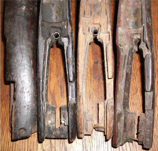
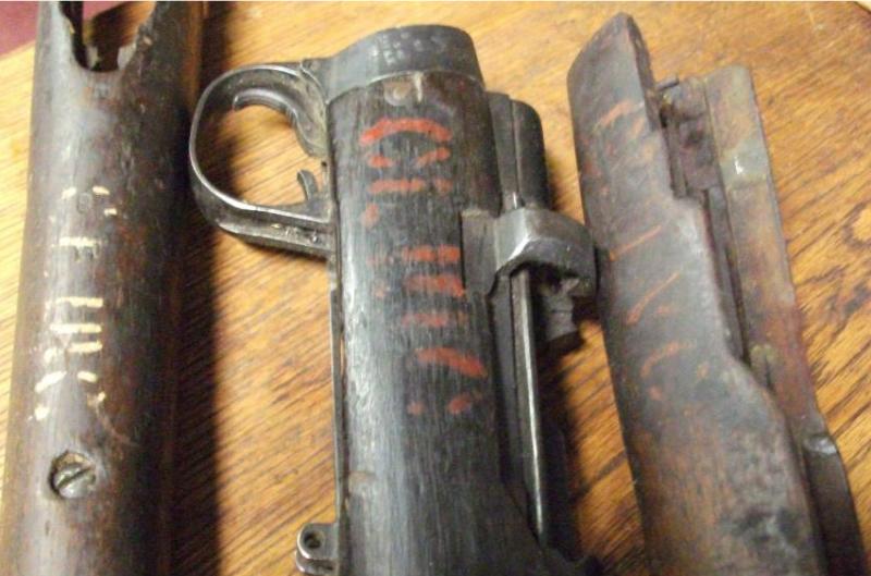
Here's some photos of failed components for your consideration. Feel free to add your own tales of woe, preferably with photos! (Even slightly fuzzy ones as some of these are-sorry! ?low batteries???)
Most of the following fractures are quite "granular" in appearance, unlike typical "fatigue failure" break lines that show a combination of fracture propagation modes. Really, if there were signs of deformation surrounding the break, it would be tempting to call it ductile tension failure, but these look more like fractures found in cast iron. Note too, that most of the components are of Indian origins according to the various markings.
The cocking piece that shows the most typical appearance for a fatigue failure in steel is an Ishapore (corrected origin of mfg on 12 Dec 2010) manufactured part. Some burnishing on most of the fracture face, showing repeated cycles before failure.
Anyway, some horror pictures!:
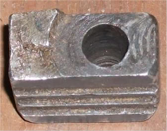
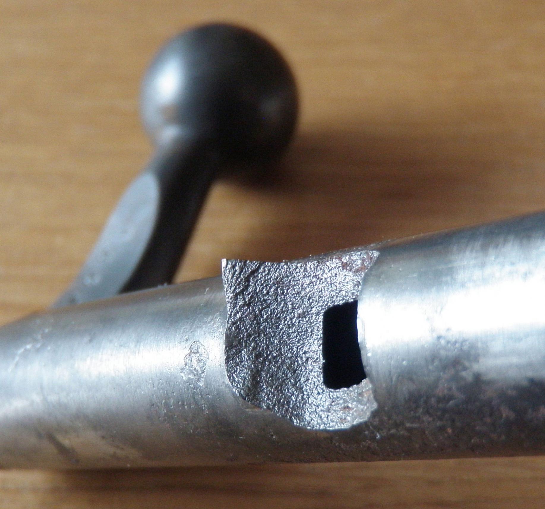
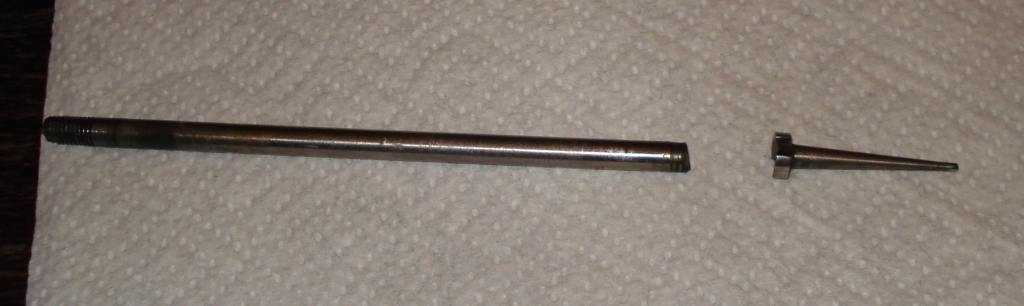
Photo#1.1-Damage on the bolt body face is due to an attempted removal of the bolt head stub.
ETA: Unfortunately, a more detailed photo won't help much here as the stub has been extensively modified in texture during some previous removal efforts.
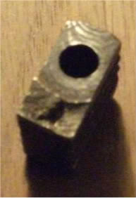
Photo #1.2a-This bolt head doesn't belong to the bolt assembly above. I've several more as well!
Photo #1.2b-ETA: supplemental photo as also shown in post #13.
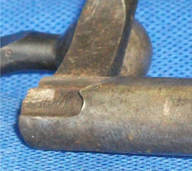
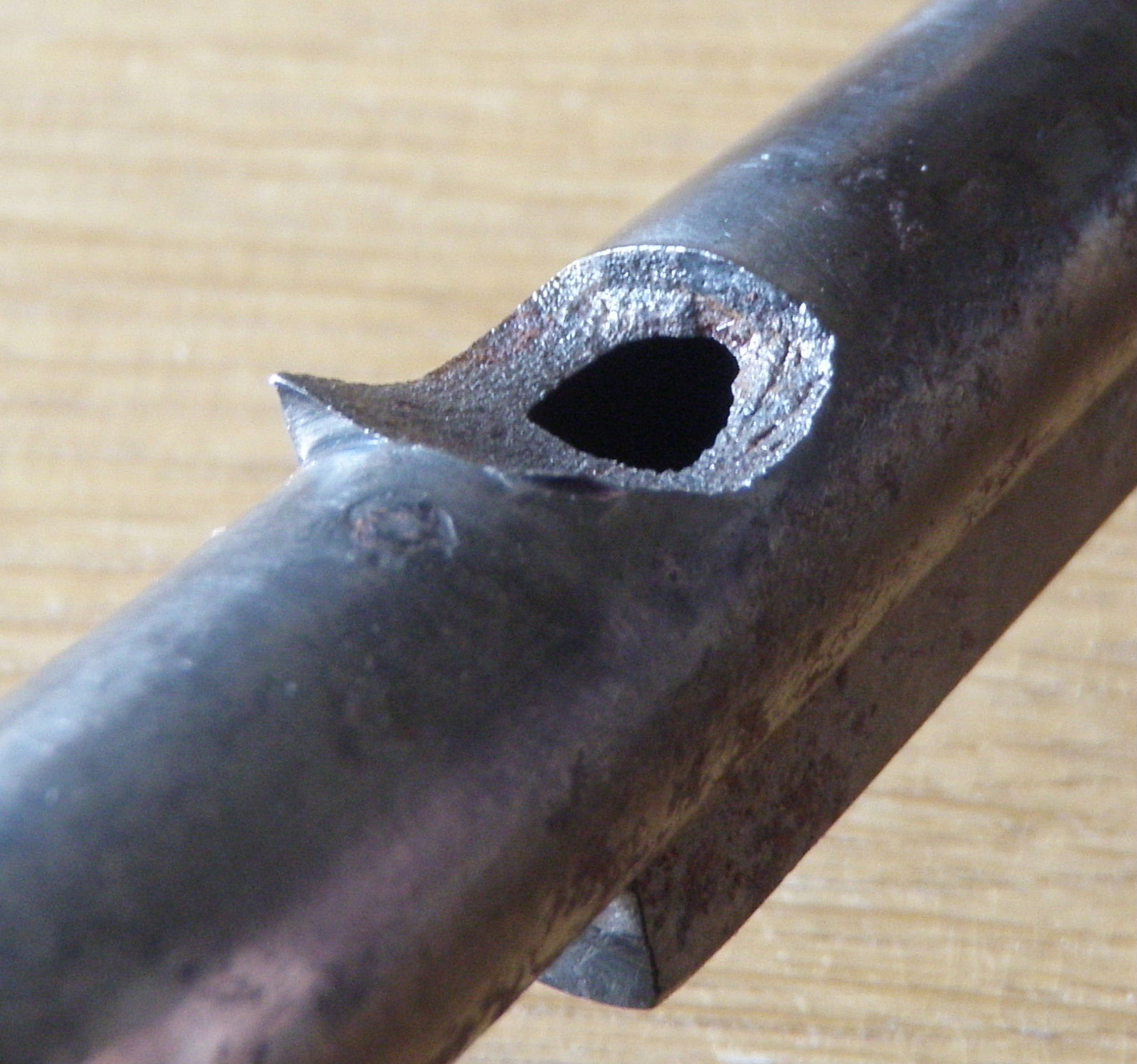
Photo #1.3a
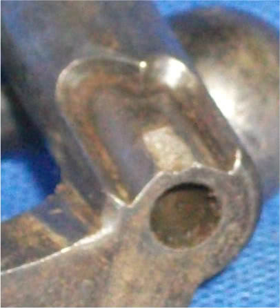
Photo #1.3b-Don't know HOW you would attempt to repair this failure! Very sad.
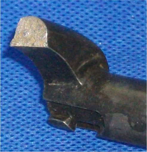
Photo #1.4a
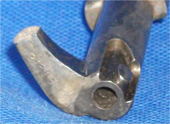
Photo #1.4b-??????
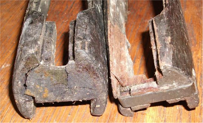
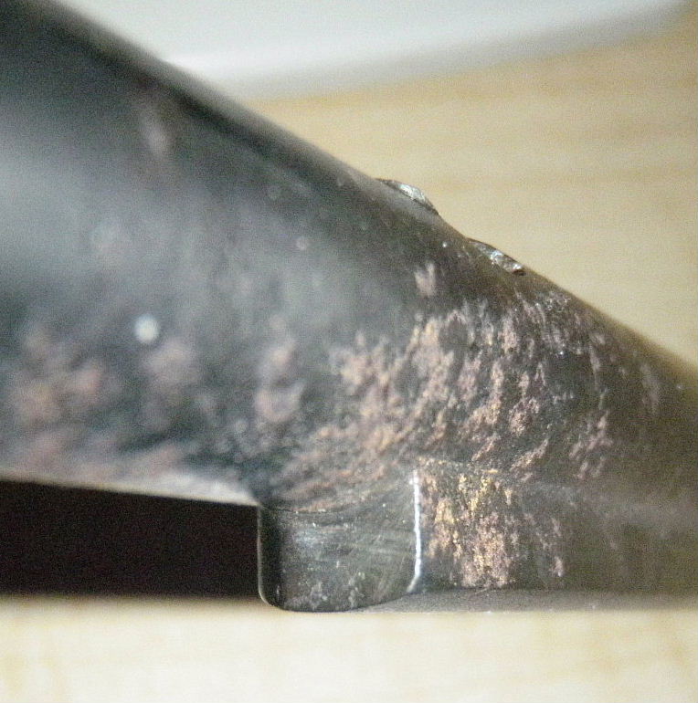
Photo #1.5-A real close up of these fracture faces would be grand. ETA- So ...there's better on post #13.
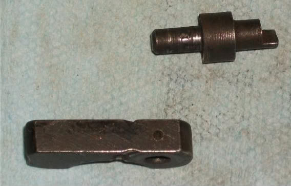
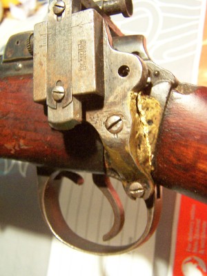
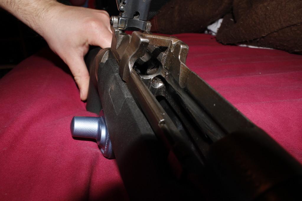
Photo #1.6- Minor failure (the cross pin) that could be fairly dangerous! Rotate the safety lever, but the cocking piece won't be restrained! Wartime emergency safety variant- worse than nothing!
Several photos leave a bit to be desired. Please give me a few days to improve the results. Hopefully, this will spark some discussion and further contributions, regardless.
No condemnation of the rifle is intended here! It's just something that I find interesting about any mechanical device- failure modes. Made a fair living dealing with it so far... and "wasted" a lot of time studying it whilst getting a degree that's hardly been used....
Peter Laidler
12-22-2010
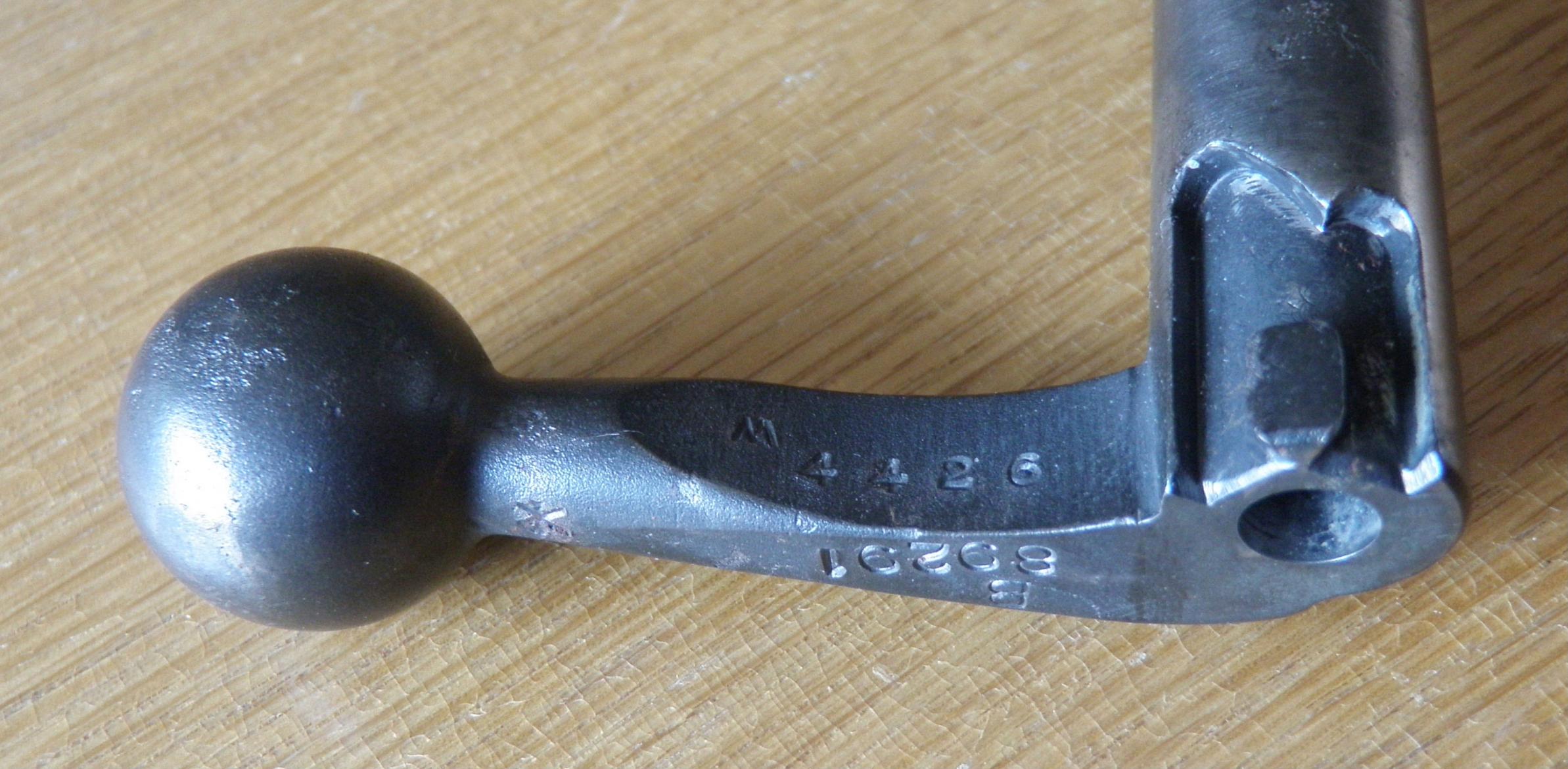
That bolt handle is the most interesting to me JM. That particular area is pretty well metalurgically speaking, stress free. I've never seen anything like that. It's a good clean break too. It would have been a good student project knowing what it is. The cocking pieces are unusual to me too as they usually break across the half bent/weak link. That's a hardening failure across the different mass area - yes?
tbonesmith
12-22-2010
I once repaired the sheered little lug on the underside of the bolt (safety lug/half cock or whatever it is) by getting a little lump welded there and then carefully filing it to the correct shape. Worked fine.
breakeyp
12-22-2010
I had the unplesant opportunity to investigate and resolve? heat treat issues in the automotive business. Given the volume of fasterners Ford uses every day, it is not surprising that problems happen. Chassis Division had 7 metallurgists/material engineers alone.
Problems can be due to:
1. Improper heat treat
2. Incorrect materials or materials out of spec
3. Batch heat treat may mean parts on the out side of the heat source don't see proper temperatures or parts too close to heat may be over heated. A hardened part may not be drawn down to the final temperature. I have seen a hardend part drop on the floor and break.
4. Slag/impurities imbedded in part leads to weak cross section
5. During the milling process at the steel mill--one billet is mechanically welded to the next and the seam becomes a srtess point subject to failure in a later manufactured part.
6. Part notched or dented during manufacturing process prior to heat treat.
A coarse cross section at a break indicates an immediate failure. If the break surface is smooth with a series of curved swirls--the failure was ductile and happened over time.
I have a three inch thick textbook from a class on the Theory of Failures that attempts to cover the subject. If someone is really desperate for reading material, I can furnish the title and particulars.
jmoore
12-22-2010
Thanks for the "Reader's Digest" version, breakeyp!
I'm thinking there's out of spec. materials dramas here, as well as heat treating issues. The cocking pieces above seem to have failed in two cases via slow crack propagation ("fatigue"), whilst the other went all at once. As it occurred in an area w/ rapid section change, it's possible heat treatment was a contributing factor, but I suspect a bit of "notch sensitivity" as well. Fairly roughly machined, most are. The Enfield example (Early type cocking piece) shows the classic crack propagation features the best (I think...they're going to be re-photoed in a few days, so maybe we'll have a better illustration.)
Originally Posted by breakeyp
I have a three inch thick textbook from a class on the Theory of Failures
that attempts to cover the subject
Yah, I get that! I still don't know of one "bible" for this subject. Most of my best references seem to be small papers and studies. ASM and ASTM affiliated, the majority; old AWS magazines as well.
browningautorifle
12-22-2010
The only one I can attest to is the cocking piece (early type) broke exactly like the one pictured. About 1972 on that one.
Steve H. in N.Y.
12-22-2010
Unsafe safety.
Removed from an otherwise very good condition rifle that I just got. I suppose this could ruin someone's day.
breakeyp
12-23-2010
I am sure Peter can say more as he is there and knows the current Britishsystem of material callouts. The WWII period part drawings I have had access to show material callouts that allow a great variance in material components/processing. We (the US) use SAE (Society of Automotive Engineers) material descriptions. This method has become world wide much like the Doctors using Latin to provide a common language for body parts. If you call out SAE 1020 steel--it means it is made to specific ingredients and there are specific heat treat procedures to obtain a desired surface hardness and it can be expected to have specific material properties. I have seen British drawing that call out material to be a stock number from a specific supplier. If he goes out of business---you have to start over. If he makes a bad batch---how to you prove it. If he takes shortcuts due to material component unavailability, how do you prove it.
Mr. Moore I can tell you have been down the road. I had some oldtimers that helped me through the maze explaining the differences between ductile and catastrophic failures. One thing they were absolutely crazy about was if a failure was attributed to material crystalization--you got a rough lecture as all metal is crystaline in nature. Steel has infinite life, unlike Aluminum, and does not change properties over time. Steel must be worked or have a weak crossection vs. load for a failure to happen. Unlike steel, rubber continues to cure, age, over time to the point cracks/failures happen. For example look at antique car steering wheels--guaranteed cracks. Re-reading this I find that I would have been in trouble at work if I had written this. Due to the lawyers, we couldn't write using the word failure. We had to say the part was unable to react to the present load.
Yah, I get that! I still don't know of one "bible" for this subject. Most of my best references seem to be small papers and studies. ASM and ASTM affiliated, the majority; old AWS magazines as well
jmoore
12-23-2010
Originally Posted by breakeyp
Steel has infinite life, unlike Aluminum, and does not change properties
over time.
Just a clarification on breakeyp's excellent post (He's gone to an extreme "shorthand" to keep from filling pages!):
Steel parts will theoretically survive an infinite number of stress repititions or cycles IF the applied stress is below a certain level. Above that point- failure will
happen. How soon can be predicted with increasing certainty as the variables are controlled (or are known), reducing the "factor of stupid". (A phrase I picked upfrom a favourite pre-PC professor)
Some parts can be designed to last millions of cycles, others don't need to last ten! It's maddenly hard to control ALL variables, though!
Mk VII
12-24-2010
Broken one on the right
jmoore
12-25-2010
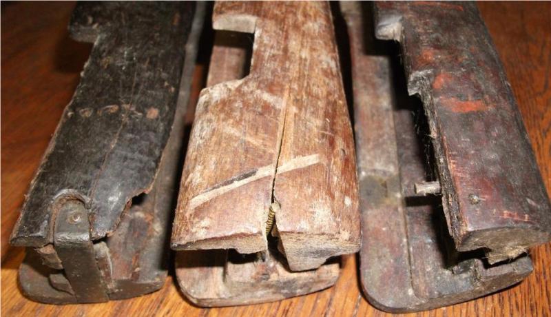
Whilst in the initial stages of Christmas "mayhem", opportunity to add a bit arose. So, here's some new material:
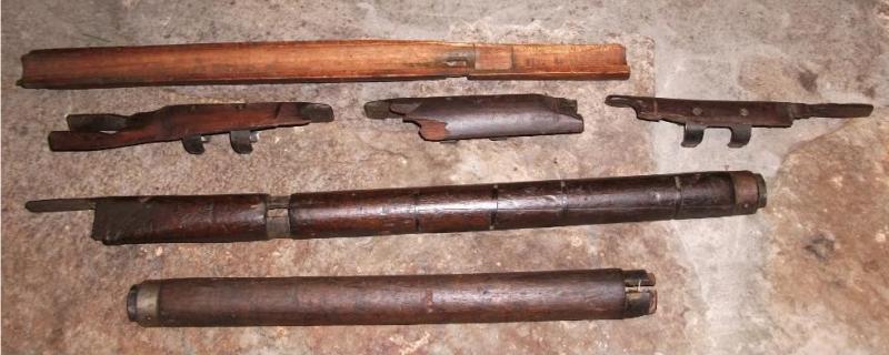
Photo #13.1a
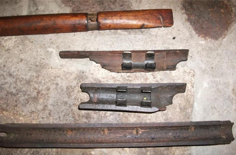
Photo #13.1b
Photo #13.1c
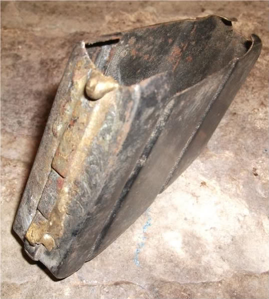
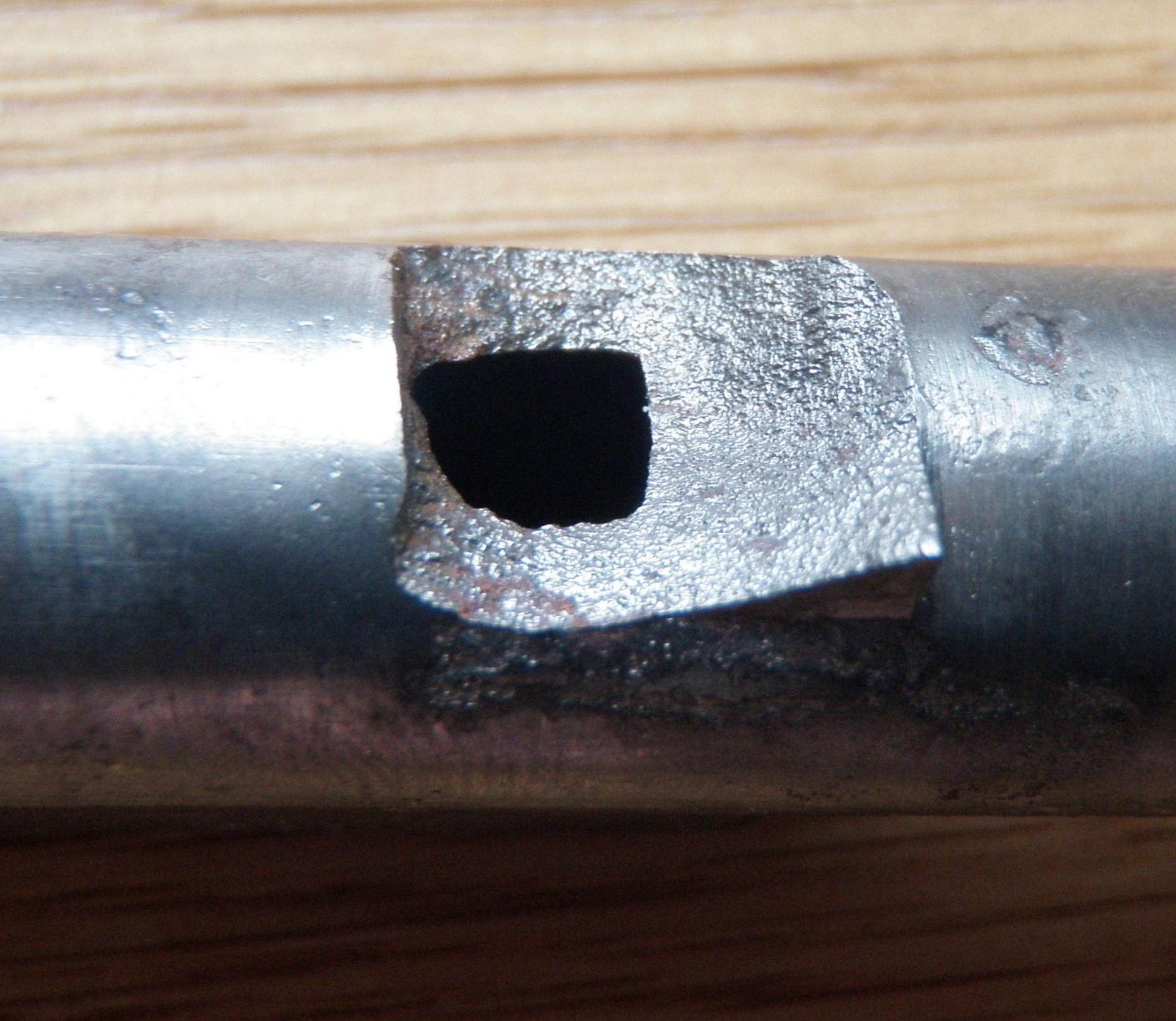
Photo #13.2-Not quite sure what failed here, but the multiple repair attempts are a horror show!
An addendum to post #1's poor photos:
Photo #13.4- FYI:This is an Enfield manufactured cocking piece.
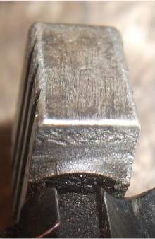
Photo #13.5b
Photo #13.6
Hopefully, these are a bit more useful!
breakeyp
12-27-2010
[cocking piece failure pictures above]
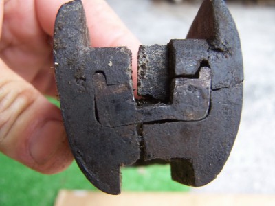
I had trouble matching the picture to the callouts and the preview won't show the picture so I am guessing I guessed right. Anyway the picture should be a cocking piece where the front area broke off from the rear cocking piece, fourth up from the bottom. The grainy cross section shows that the failure happened all at once. In the upper right hand corner of the exposed surface, you can see what appears to be a Y or crow's foot change in material appearance. I suspect the failure started at this point and propagated across the whole surface with little warning that it was going to happen.
If the part had been due to fatigue--where the part is subject to a series of bending, relaxing and bending again, the failure surface would have shown a series of circular marks with the start point of the failure being at the center of the failure. Bending a wire back and forth until it breaks is a good example of fatigue or dynamic failure. Breaking a stick or shearing a bolt off is an example of catastropic failure as there is no warning until it happens.
jmoore
12-27-2010
This one, yes?
Copy of "Photo #13.4"
Don't know why it didn't show in your post, breakeyp.
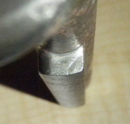
BTW, it was LIGHTLY scrubbed w/ a wire hand brush of 0.002" wire size before the photos to clean away cruc and corrosion, which may have rounded the edges a bit.
jmoore
12-28-2010
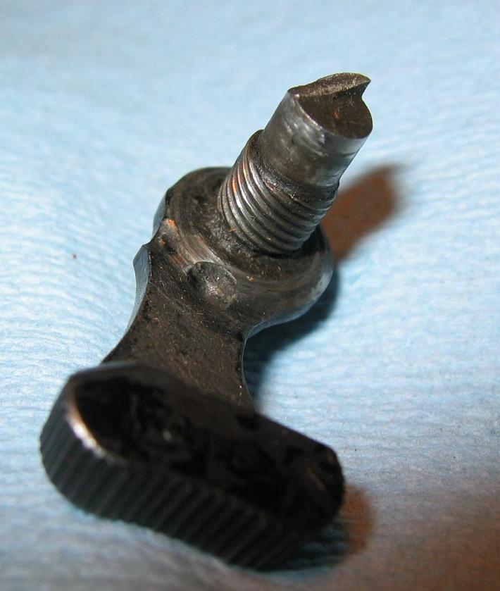
BTW, the more typical slow crack propagation (Fatigue failure) example as described by breakeyp above is illustrated by the cocking piece stub still attached to the bolt assembly. However, it's not an Enfield part after all, it's Ishapore. Don't know why I stated the contrary earlier! (Post #1 corrected to show proper mfg. origins.)
breakeyp
12-28-2010
Thank you for the photo help. I can remember my materials people beating me up for fitting a failed part back together before bringing it to them for analysis. They felt that it would alter the failure surface. Their analysis used high power microscopes and they could tell if I did it. So you can imagine my cringe when you said you wire brushed it. Boy, they sure could put the fear into you. After all the fiddling around they did, the best they could really tell you was if it was an immediate or overtime failure and the direction from which I started.
jmoore
12-28-2010
That is why I thought it important to mention. However, due to years of poor storage beforehand, they were of even less value "as is"! Didn't know we were going to get as involved in the "nitty-gritty" at first. In actual fact, IF I had some way of doing super macro shots, much detail is still usable. Lemme cipher on it a while...
I think there's another cocking piece untouched somewhere, as well. Off to edit and clean up some previous posts to make references easier. (Destroying their historical value! The posts, that is...)
RJW NZ
12-28-2010
A little wreckage, a 1918 BSA. The sight middle screw was once upon a time, stripped then the head cut off and put back in the hole, the whole sight then being braised to the wrist. When I opened it up my 'shootable' enfield had major yikes! issues. Time to break out the West epoxy.
jmoore
12-30-2010
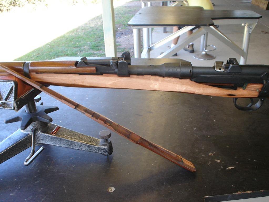
Fortunately for y'all, RJW NZ made some good photos of a distressed SMLE Mk.III* fore stock (Post #20), otherwise...
There's no escape, however, as warned- here's a little more:
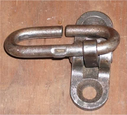
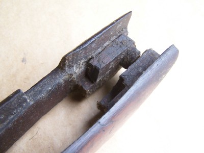
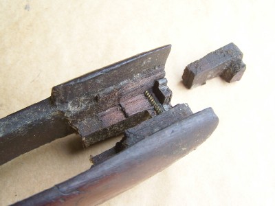
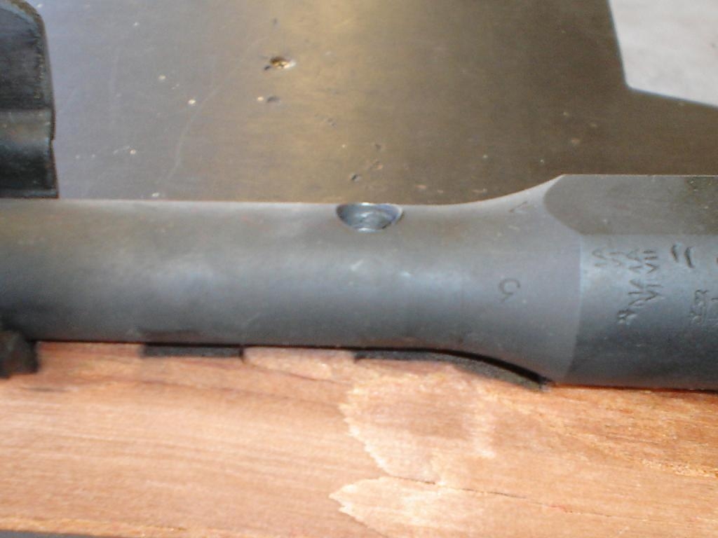
No.4 Savage rear swivel assembly that's come adrift. Not a major crisis, but probably annoying if it occurred in the field.
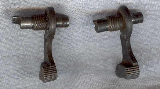
Another cocking piece- uncleaned this time, but not as filthy as the others. Failed in "stages" on TWO roughly parallel planes which were joined by the fracture in the center.
Will try for some more shots of this one if anyone's interested.
Have yet to root through the old barrel pile!
Mk VII
02-30-2010
Seen several of those staked swivels fail. One can get them welded up again, and "good for another sixty years".
breakeyp
12-30-2010
Playing the Ford Motor Co. game, an FMEA (Failure Mode Effect and Analysis) of the poorly staked swivel could be due to:
For the swivel, material incorrect, material diameter not correct, upset incorrect due to tool wear, out of print or movement of anvil during staking operation.
For swivel base, swivel hole oversize, incorrect material allows hole to deform during staking operation and not grip the upset.
Staking operation: Insufficient pressure during staking, anvil/fixture movement during staking opertion. Slippage during insertion of wire staked area in the base (If that is how they did it).
Without knowing the process, one can speculate even more issues/concerns.
Comment for what they are worth. This speculation would be followed up by a visit to the manufacturer and deep analysis of his assembly process and controls to insure it does not happen again. Apparently Savage didn't get the message or their sub supplier.
Claven2
12-30-2010
I love this thread, though I can't for the life of me understand those cocking pieces being broken so frequently in that spot. Frankly, apart from resisting spring pressure at the sear, it's not an overly stressed part. The fracture looks, to me, like an impulse fracture and not a ductile one from plastic deformation. This suggests over-hardening in the metal structure, possibly martensitic steel throughout, while Pearlite with a hard surface or Bainite throughout would have been a much better heat treatment goal for these bits. But then, it's possible that the manufacture was bunged up to begin with and the wrong hardness was the result.
The bolt heads aren't failing in tension as the bolt design would not generate enough force on extraction. I'm thinking it's a combination of too much bolt head slop in battery coupled with uneven wear on the locking lugs causing uneven shear stress on firing. Again, the fractures are not from plastic deformation but look immediate.
One failure I've seen fairly often (no pics though) is the receiver wearing out such that the bolt has too much vertical travel causing iffy sear engagement. You see it on receivers with a lot of miles on them, and more often than not a few rebuilds, some of which were probably done in India where one wonders if the armory had gauges.
I have also seen the receiver bridge inserts fall out on some No.4's, presumably from some shock to the receiver.
breakeyp
12-31-2010
Consider the relationship of the cocking piece and sear engagement. Smartly slamming the bolt home generates a high stress on the nose of the cocking piece as it hits the point of the sear. I suspect that a condition called impact loading might enter here. It has been years since I fiddled with this stuff, but as I remember there were formulas that tried to account for the addional loads encountered when things were slammed together. High loads and the offset difference between the area (notch effect) of the cocking piece body and the extended nose of the cocking piece and the point of contact with the sear nose creats a moment (force moving on a radius of action) that can put quite a tearing force on the cocking piece. If there is a weakness, sharp corner, material hollow/inclusions--- the part breaks. Like many engineering formlas, you have to make real world tests to get the constants you need to make the formula work for that particular case. In school you were given frictional constants for problems but in the real world you had to test to find them and then proceed with the caluclations that may work or may not. Thank God for safety factors where you design for parts to accept 4 or 5 times the expected loads.
I hope this hasn't bored you too much. It is hard to do this stuff without paper and pencill.
Claven2
12-31-2010
Yes, there is a bending moment about the base of the elongated part of the cocking piece, but the forces involved should be more than manageable for a machined and heat treated part, even a case hardened part I should think. Given the relatively low instance of failure, I'm more thinking there was something intrinsically wrong with the specific parts that broke and not a general design fault at play.
Brian Dick
12-31-2010
If the bolthead, firing pin, cocking piece assembly isn't fitted and timed together properly, the slapping of the cocking piece on the back of the bolt body will eventually shear it. Myself and others here have advised folks till we were blue in the face that there's a fitting process involved when replacing boltheads. It's not just a case of screwing in a new one and "Bob's your Uncle"! I suspect that many of the cocking piece failures are caused by incorrect fitting of the bolthead.
Claven2
12-31-2010
I suspect many of the bolt heads shearing off are also due to the same cause. That being said, I find a No.4 bolt head is generally likely to fit right away while a No.1 bolthead requires many spares to achieve a good fit to a given bolt body.
Peter Laidler
12-31-2010
We've mentioned the rotating action of the cocking piece when it strikes the sear, which also takes a good dollop of impact loading as I call it. But while we used to see loads of broken sears in our Armourers shops, are they a feature in the commercial world as we haven't had a photo of a snapped sear. The young and unwise, the enthusiastic amateurs as I call them, would try to adjust the pull-off by slightly bending the sear. But the sears wouldn't have any of it and snap at the first opportunity.
From the pure engineering point of view, this is a great thread, getting better! I'm inclined to agree with Clav on the broken sears in that it's a failure in the whole of the hardening and tempering process. Put simply, (to take into account my 2nd year metallurgy or hide it!), the sear bents area has to be hard but the remainder has to be tough. I used to see them snap across the safety sear/half cock bent and to see several broken across the 'join' between the two different masses is rare for me but is sooo illustrative.
Breaking across the bolt head tenon/threaded shaft like that is a bit of a teaser and I'm thinking catastrophic due to shock loading (yes, I know you're asking... where does it come from and HOW does it manifest itself there?). That would make a super and interesting student project. Brian has raised a good point and that is the simple fact that the bolt has to be looked at as a whole unit. I wonder if that's why we (in the Military) would see plenty of cocking piece failures across the safety/half cock bent, we didn't see the other failures.
I wonder how the meister Ed H would have interpreted these failures...
Son
01-02-2011
It seems strange to have to say this (and embarrassing too) but not all sears are as hard as a bulls forehead.
Forgive me Father, for I have sinned...
I was given an sportered MLE (Sparkbrook IIRC) action that needed thirty pounds (measured) on the trigger to release the bent from the sear. The bloke had bedded the action in acraglass about a quarter of an inch thick in sportered No4 foreend without relieving any wood. Then he had cut into the foreend at the front of the trigger guard until the ball and socket MLE trigger and sear reached the cocking piece. The ball and socket joint actually bound tight at full extent of travel before the sear released the bent.
"Can you make it a nice crisp three pounds with minimal drag?" was the request. "Oh, and don't upset the bedding- it shoots ok"
I ended up putting in an SMLE sear and trigger, but the sear was too wide and didn't release the bent. I could have built up the nibs on the trigger, but I thought I'd try something else first. I sat the sear on one end on the bench, the other end directly above it. I then hit it with a hammer! (HARD) Much to my delight it didn't break, but did close up about half a mm and with a little stoning of one trigger "nib" I achieved his "three pounds with minimal drag", assembled it quickly and returned it- resisting the urge to convert the owner to a rifle bucket!
PS, swapped some emails with Mr Horton the other day. He's very good and wishes all his mates here all the best for the season.
jmoore
01-03-2011
Originally Posted by Claven2 I love this thread, though I can't for the life of me understand those cocking pieces being broken so frequently in that spot. Something that came up in one of Spinecracker's threads may help explain part of the reason beyond those already listed: Inspection stamp impressions located in the stressed area! The localized deformation is a perfect nucleus for "fatigue failure" in an area that wouldn't otherwise be expected to see large cyclical loads. Little things can make a huge difference!
Link to Spinecracker's thread below, ref. Posts #53 through #58- possibly more.:
Railroad bogeys (wheels, specifically) were one of the first well investigated items where tiny inspection stamps in the web led to catastrophic failures (and some derailments!) long into their service lives. I know that Glock Inc. moved the location of their slide proof marks away from the ejection port for the same reason. (I may have even been the one that first recognized the problem, but I can't verify that suspicion- Austria wasn't very forthcoming at the time when dealing with new dramas.)
Other "crack starters" that spring to mind that don't lead to immediate failures: Machining marks, heat treatment micro cracks, Chrome plating, random scratches, corrosion pits... Aside from the Chrome, many of these features can be very small!
Bruce_in_Oz
01-04-2011
Regarding SMLE cocking pieces:
From: Specification S.A. 462 P, Dated 14 December 1938 -
"22. Cocking-piece, "B". - Will be gauged for width and figure, position and diameter of keeper screw recess, threads, and position of looking-bolt recesses, The cocking-piece to be hardened from the bent, including the second locking position; it is then to be tempered to a spring temper from the head to the safety bent, the full bent being left a straw colour. The cocking-piece will be examined and tested for hardening and oil blacking or browning."
Note there is no hint of Rockwell or Brinnell numbers. The entire process relies on the skilled eye and sense of timing of an experienced tradesman. Not only that, but the standard of lighting was probably not exactly uniform in the heat-treating room. Cloudy days, night shifts, hangovers...
Peter Laidler
01-07-2011
That's an interesting piece Bruce. It's almost archaic now and as you say, just SOO subjective too. We used an old IZOD tester to test the body locking lug and bolt lug hardness at the big Base workshops. It was a ball impact at a certain load. Certainly no Brinnell or DPN. When they were doing the trials to test the suitability of a longer bolt head, they used a similar testing method. But as I mentioned, it was soon established that if a rifle had run out of CHS on a No3 calibrated bolthead in the gauge, inspectors, bolt, then the hardness had broken through or down
Claven2
01-07-2011
Ah yes, the wonderful IZOD method. I work with a lot of milspec UK kit and almost all of the old specs call for IZOD while here in North America most of the specs I see are based on CHARPY testing. Not sure why the British penchant for IZOD, but if memory serves the IZOD test require more sample prep and therefore always annoyed me back in the day.
Of course, apart from batch stock proving, most of our testing these days is NDE such as ultrasonics, LPI, etc.
Bruce_in_Oz
01-08-2011
I stand to be corrected, but I think that the cocking piece is NEVER meant to strike the rear of the bolt body.
The collar on the striker is absolutely intended to strike the rear of the bolt head. This does two things: 1. Ensures constant striker protrusion, and, 2. Drastically reduces the potential for damage to the thread / mating surfaces at the tail-end of the striker.
The first point is tied in with the selective fitting of the striker to the bolt head. This was, I understand, done as part of selecting a set of components to assemble a bolt. The idea is that gauged components were selected for "best fit'.
The bolt lugs had to have the correct amount of engagement with the shoulders in the receiver.
The bolt head had to fit so that the "wing" of the head lined up with the lug on the bolt body or no more than a few degrees over.
The striker had to fit the bolt head within the specified protrusion range.
The striker had to tighten into the cocking piece such that:
a. The protrusion previously set was maintained,
b. The keeper screw would enter the rear of the cocking piece and prevent rotation, and,
c. The safety notches in the cocking piece would be correctly aligned with the driving surface of the locking bolt when cocked or at rest.
Remember that early SMLEs used a striker that had a lug which lined up with a notch in the rear of the bolt head. This was to ensure that if the bolt was not closed fully, the striker could not ignite a cartridge and do some serious damage. This required some seriously fine machining to ensure that the lug was correctly aligned with the keeper screw recess at the rear and, just because they could, the qualifying of the thread at the rear of the striker. This striker required a LOT of careful setup and gauging during manufacture. It is not surprising that "Striker 1B" replaced it as part of the process of increasing production rate. "Striker 1B" is the common model with the two cutouts that are engaged by the striker assembly / removal tool.
jmoore
01-08-2011
Originally Posted by Bruce_in_Oz
I stand to be corrected, but I think that the cocking piece is NEVER meant
to strike the rear of the bolt body.
You're not wrong, I believe Brian Dick mentioned this point as well in a previous post!
It occurs to me that the other likely outcome of cocking piece impact onto the rear of the bolt would be sheared firing pins somewhere near the thread origins. Oddly, I've none in the "dead parts " stash!
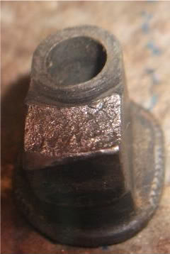
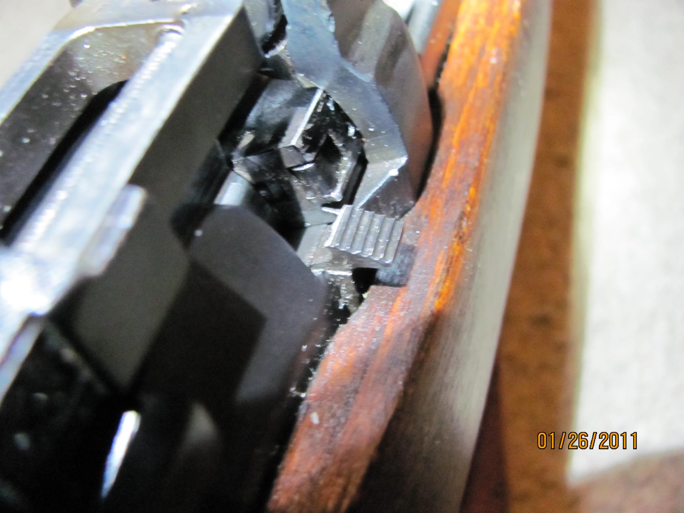
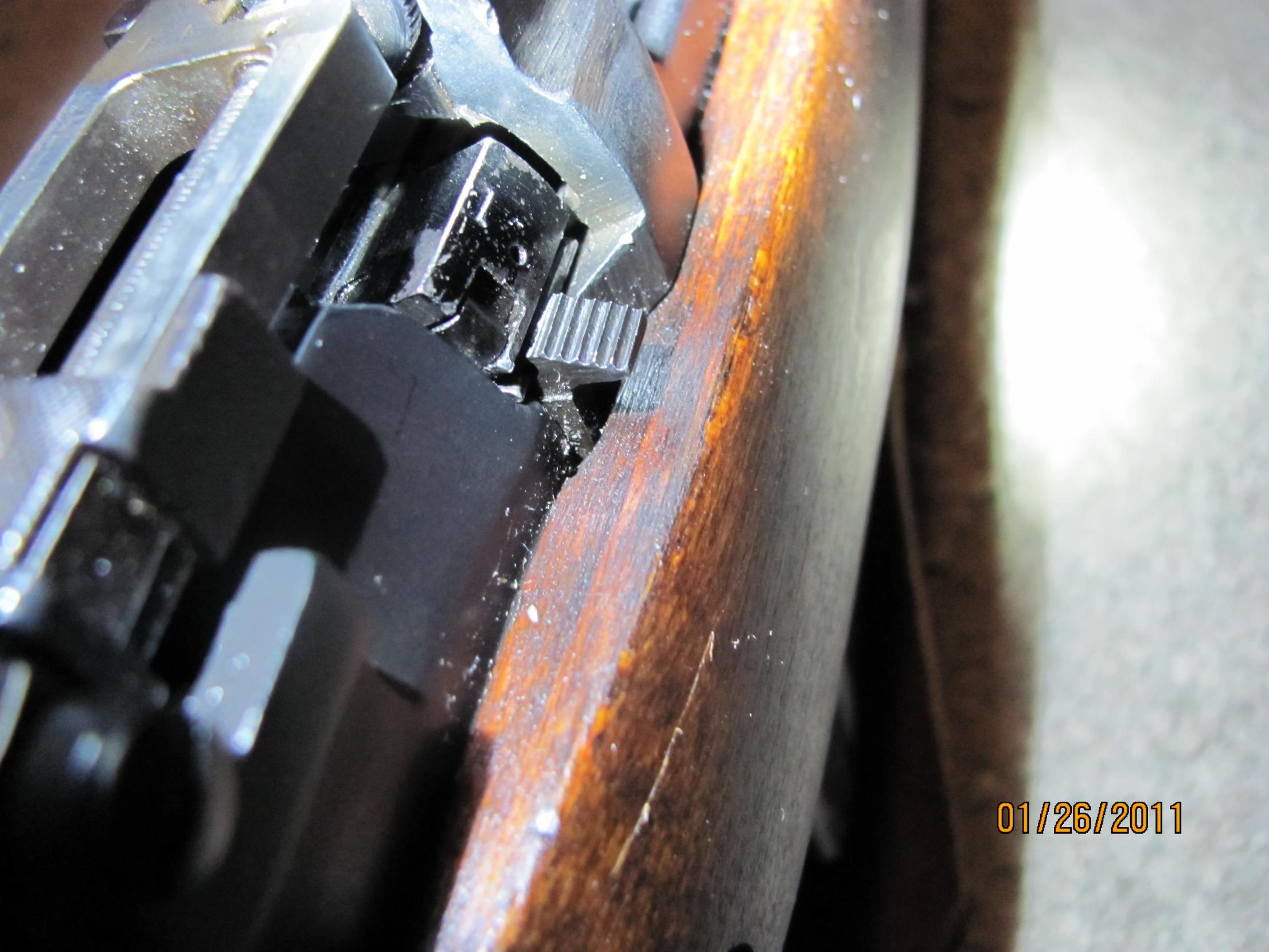
ETA2:So the burnished or shiney face surrounding the firing pin hole of the cocking piece below is likely significant!
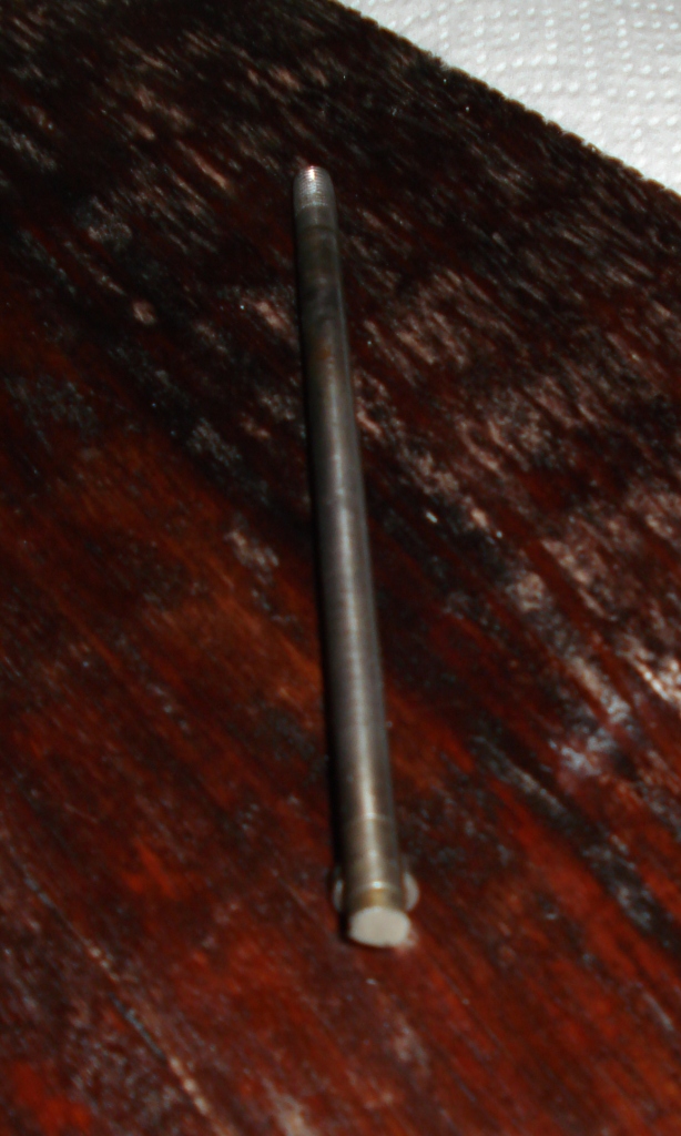
ETA1: Whilst posting, here's some supplemental photos to subjects previously introduced:
The uncleaned cocking piece showing the multiple roughly parallel (or slighly convergent?) fracture planes that are linked by a longitudinal fracture. Ref. Post #21
Son
01-09-2011
I wasn't sure about which thread to put these pics. As I do not have any accompanying information other than it is a DP rifle, maybe it's better off here as a failure, albeit on the head of the operator...
P-07ShortLee
01-14-2011
Interesting photos. Out of all of them maybe the worst (since it's so common compared to most of these) is the one J. Moore posted of the "usual" split forend from someone's attempt to disassemble without knowledge of how to do so.
I have also seen bent and "repaired" stock bolts to add to the list (no pics).
jmoore
01-15-2011
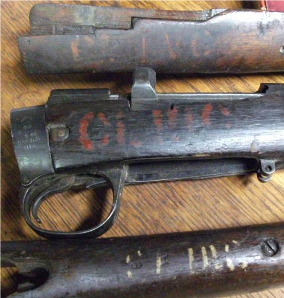
Time for more carnage:
Whilst in the pile, got some photos of painted markings that might be pertinent to the sorry condition of these components. Can't get a good read on 'em. Any thoughts?:
5thBatt
01-15-2011
Originally Posted by Bruce_in_Oz
Remember that early SMLEs used a striker that had a lug which lined up with
a notch in the rear of the bolt head. This was to ensure that if the bolt was
not closed fully, the striker could not ignite a cartridge and do some serious
damage.
The lug on the firing pin and the notch in the bolt head are aligned the moment you clip the bolt head down onto the bolt head rail, neither the bolt head or the firing pin rotate while working the bolt, if the bolt is not closed properly when fired, it either closes fully itself or goes into the "half cocked" position.
jmoore
01-26-2011
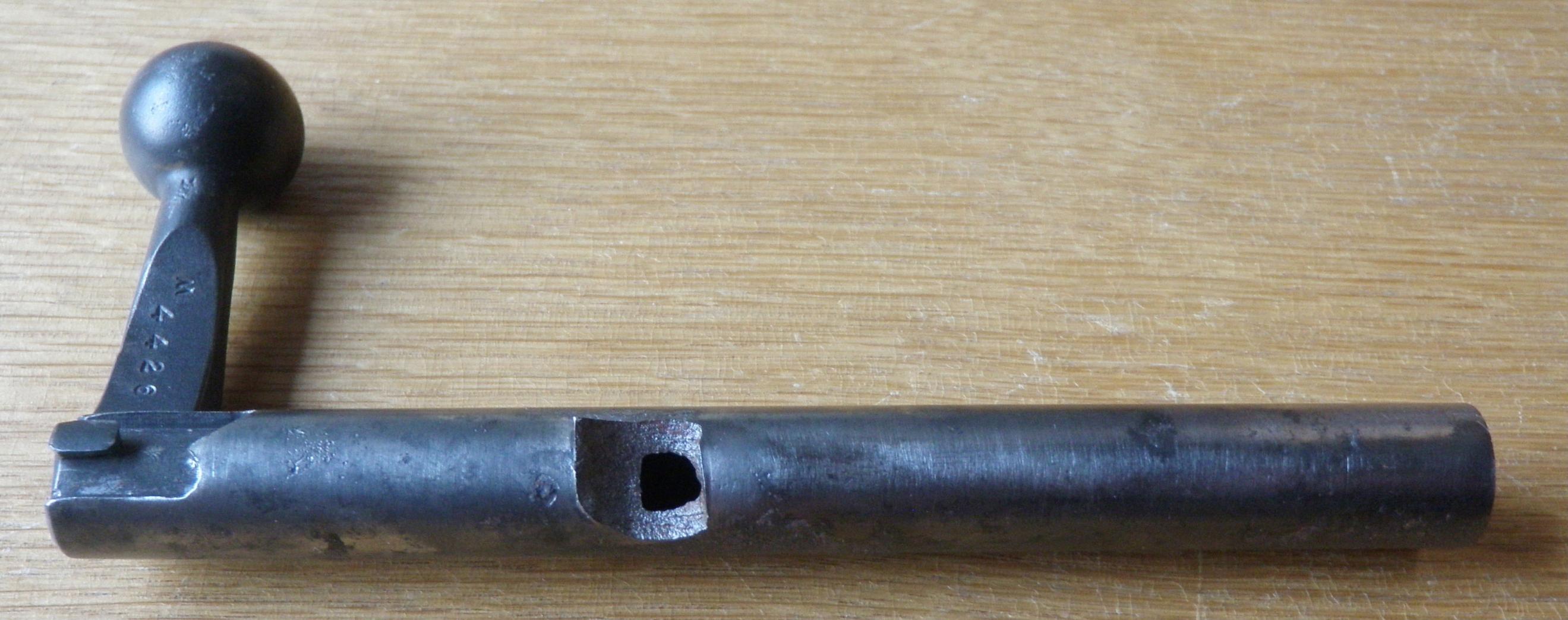
Link to CMP"s thread which shows a curious No.4 Mk.I with an even more curious fractured bolt catch :
http://www.milsurps.com/showthread.php?t=28360
See post #8 for a close up view
http://www.milsurps.com/showthread.php?t=28360
5thBatt
01-15-2011
Originally Posted by Bruce_in_Oz
Remember that early SMLEs used a striker that had a lug which lined up with
a notch in the rear of the bolt head. This was to ensure that if the bolt was
not closed fully, the striker could not ignite a cartridge and do some serious
damage.
The lug on the firing pin & the notch in the bolt head are aligned the moment you clip the bolt head down onto the bolt head rail, neither the bolt head or the firing pin rotate while working the bolt, if the bolt is not closed properly when fired, it either closes fully itself or go's into the "half cocked" position.
jmoore
01-26-2011
Link to CMP"s thread which shows a curious No.4 Mk.I with an even more curious fractured bolt catch :
http://www.milsurps.com/showthread.php?t=28360
See post #8 for a close up view
Surpmil
01-27-2011
SMLE bolt that was probably swapped into a different rifle without lapping in the recoil lugs.
jmoore
01-27-2011
Outstanding, Surpmil! What does the other lug look like? No problems, yes? So all the load was probably absorbed by the one small lug, I reckon.
Interesting dicolouration at the front. I wonder if there was already a partial failure existing when the bolt was refinished, or...?
Surpmil
01-27-2011
No sign of any damage to the main lug, and you'd blow the rifle apart long before you made that lug fail. I think the broken lug might in the box too, I'll see.
Peter Laidler
01-27-2011
I can't see the discolouration properly but the steel structure looks to me as though the discolouration is in fact part of the hardening process. Metallurgy comments JM?
jmoore
01-28-2011
The discolouration indicates that area was exposed to either air or chemicals whilst at least partially broken. However, I won't get a reall good look until later. Computer challenged at the moment (Old PO$ monitor!)
jmoore
01-28-2011
Using a better monitor only raises the uncertainty level! I've no idea what the discoloured area implies any more.
There seem to be small smoothed over areas at the front and, to a lesser degree, rear of the breakout. Also a colour change just forward of the lug.
There's no real sign of a slow progressive failure from what can be seen here. But...
Other things noticed:
Odd overall grey colouration of the bolt
Possible post break clean up in the lug area, or it's slightly out of focus- hard to say.
The large pit to the rear of the lug looks a lot like the sort of "spalling" oxidation found on fire damaged items, but again, nothing certain.
Other old pitting on the rear of the bolt looks like regular old corrosion.
There's a little newer rust on it, but that is to be expected!
It just LOOKS exactly how one would expect a broken lug area on a bolt ought to look! Whether or not there were multiple contributing factors, it's an excellent illustration.
Surpmil
01-28-2011
Well let me eliminate some of the guesswork: the bolt came in a box of bits, it was rather rusty and had the attention of my finest rotary wire brush, which is very fine indeed. I don't think it affected the broken area at all, other than to remove the surface rust. The wheel used lightly as I did, does not really affect colour at all in my experience, other than to show what the colours really are when the dirt and rust comes off.
There is considerable rust pitting all around the bolt just aft of the fractured area. The original finish on top of the main recoil lug/shoulder and on the bolt handle shows hardly any wear, so this was not used long and hard before failing apparently. It does look a bit like someone filed the bearing surface on the main recoil lug or shoulder however, so if that area was relieved too much, one would expect excessive loading on the lug that failed.
Peter Laidler
01-29-2011
Yep, I think you've hit the nail on the head there Surpmil. The whole of the recoil load was taken on the smaller locking lug. Maybe a couple of rounds before had started the fracture process then it went. A fantastic example for a class, especially during bolt fitting. A brilliant example and in the nicest sense of the word, a pleasure to see. Agreed JM? Thanks Surpmil
jmoore
01-29-2011
Agreed! It's almost like a test piece.
plate
03-11-2011
On the recommendation of other board members I would like to contribute my photos for your enjoyment.
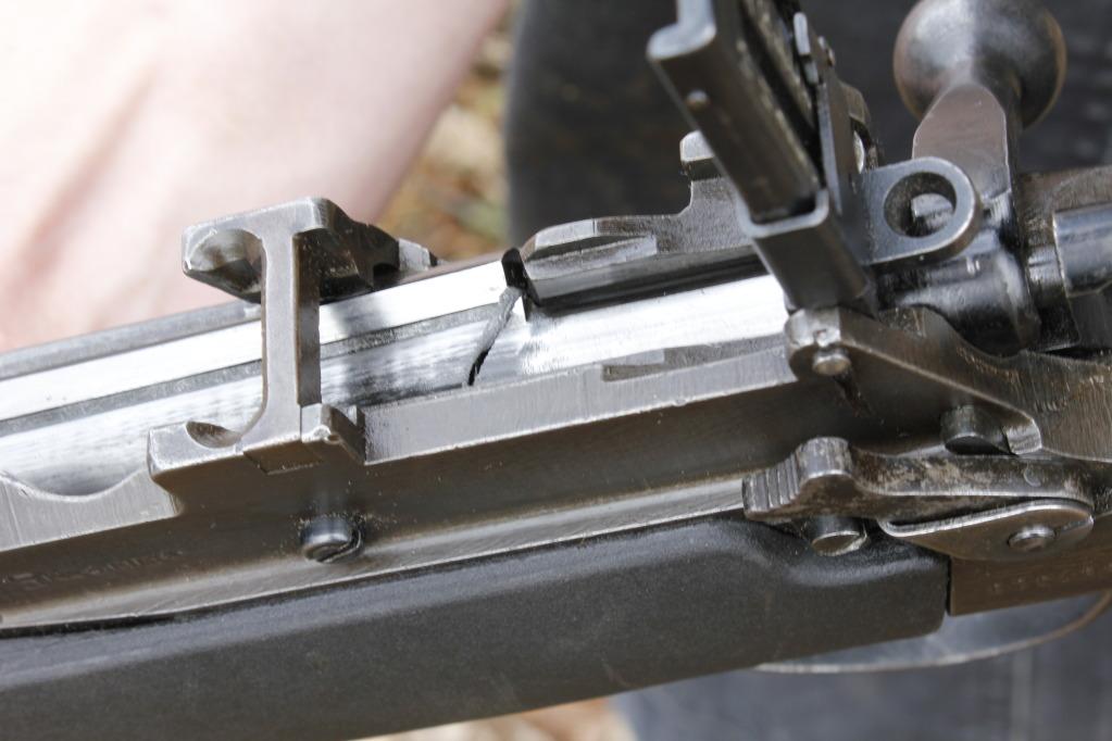
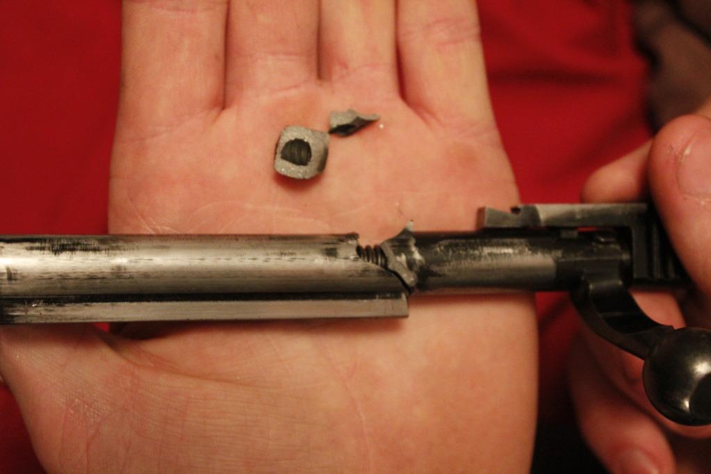
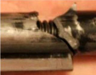
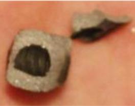
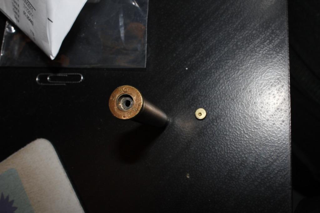
Details as they were, rifle clean, well oiled, Remington 303 Brit 174 gr, approx 25 rounds down range. Last round had a bad primer and pin went all the way through allowing some blow back of pressures.
Here is what I found inside:
Peter Laidler
03-11-2011
I haven't seen a striker broken behind the collar either. But there's no reason why not I suppose depending on the tempering.
jmoore
03-12-2011
It's not an Enfield part, but Snafu has a thread on the "M1 Garand/M14/M1A Rifles" forum that shows a pretty classic "fatigue" failure of a firing pin. No micophotographic techniques required to see the origin point, progression of the crack and the area where the final catastrophic failure occurred. No mystery there!
Link here: Firing pin failure last weekend http://www.milsurps.com/showthread.php?t=29593
Claven2
03-30-2011
A new one popped up today on CGN, aparently happened using factory Belmont ammo. This one is a first for me
Based on the limited info provided by the poster, this is what I answered so far - though very difficult to diagnose from one picture over the internet...
I'd need to see images of the failed surface, but from the photo you posted, the failure looks more like an embrittlement fracture and not a shear failure. I think I see crystaline texture indicating the presence of martensite throughout the cross-section. This is not good for a part seeing impact stress.
I would tend to suspect the bolt rib on the handle-side was the bearing rib and the base of the rib where it meets the cylinder of the bolt body experienced a catastrophic fracture due to a non-rlieved stress point in the bolt from manufacture and subsequent hardening of the bolt.
Without more info, I'd chalk this one up to an unlucky hot round meets less than ideal wartime manufacturing practices with respect to heat treatment and the quench temperature being off before the bolt was reheated for stress relief.
The receiver looks to be a Savage, no idea what maker the bolt is, but the handle does look altered...? Has it been ground on or heated and bent? Perhaps subsequently water quenched? This could also embrittle the bolt to the point of failure during firing.
Brian Dick
03-30-2011
Interesting. I have the rear half of a bolt sent from a guy in Florida from a new No.4 Mk.2, sn. A956 broken completely in half in the exact same place. It was a hot reload that caused the failure on this one. It blew my mind when he sent it. I'd never seen anything like it before.
The top of the bolt handle on the pictured bolt has been dished out to clear a scope at some time. I've seen them done like that before.
jmoore
03-30-2011
Immediate question that arose in my little pea brain is whether both locking lugs bore against the receiver body. Off axis loading to be sure, but that would take a boatload of action flex! Not a compressive failure, I don't think.
Brian Dick
03-30-2011
The rear half of the bolt I have is broken almost identically on both lugs with the break running forward. The one pictured looks pretty much identical except you can't see the other side for the body. The break is triangular looking from the top. I'll take a picture and send it to Badger tomorrow since I'm electronically challenged. As I said, t came from a newish, matching No.4 Mk.2 that was being used in high power competition in Florida. You would think it doubtful that the bearings of the locking lugs was ill fitted or uneven. Of course ROF Fazakerley did have some quality control problems according to those in the know.
Thunderbox
03-31-2011
Even with a mismatched bolt, it would take a tremendous overload to shear the bolt body. Wonder what happened to the bolthead & cartridge case? Perhaps this was an overload on top of an obstructed bore?
The trouble with these cases is that the rifle and ammunition are never available for inspection subsequently...
jmoore
03-31-2011
Except for Brian Dick's example! Let's see what his photos look like...
A more detailed study of the entire action pictured above would be quite helpful. Hard to beat a hands-on examination, though, but, hopefully this thread will encourage study of such failures to at least make some sort of useful conclusions. Otherwise, the odd random photos will drive all sorts of rumors. It seems that most (90%+?) catastrophic failures of varios types of weapons I've seen "in the flesh" were caused by handloads. NO weapon is failure proof against some folk!
Claven2
03-31-2011
Another photo surfaced:

I now think the faliure originated on the left side lug, which broke completely off, and then propagated to a stress point at the base of the safety lug. Uneven bearing could be the culprit, IF it was VERY bad and the load was hot.
Peter Laidler
03-31-2011
Although we can't see the grain structure too well, I agree entirely with clav. Uneven bearing, whole load taken on l/h lug and something's got to give. Mind you, is that a penetrative oil staining at the left and right hand end of the broken lug? Or is it some camera shading? If it's oil staining, it indicates an earlier fissure which would back up Clavs observation that it's an uneven bearing over a period until...
GREAT student projects...
Are you non-too-technical forumers enjoying this thread discussion as much as the technical bods are?
vintage hunter
03-31-2011
Comparing the photos to the earlier ones of a sheared left lug it appears that the fracture on this one actually started towards the top of the lug and travels down through it at an angle leaving part of it still attached to the rear half of the bolt body. Weird.
paulseamus
03-31-2011
Could a partially closed bolt, from shallow set primers, also contribute to an uneven loading on the two locking lugs?
Peter Laidler
03-31-2011
It COULD be in theory Paul but due to the inbuilt mechanical safety, you cannot actually fire the rifle until the bolt is positively locked. On the reverse side to that and thinking about it, you couldn't replicate the situation by half opening the bolt AFTER firing because you can't unlock the bolt until the pressures have dropped to atmospheric.
Brian Dick
03-31-2011
In all my years and hundred of Lee's through my hands, I'd never seen anything like it up until Claven's post.
"Just a couple more grains of powder ought to do it there Jethro!"


Peter Laidler
03-31-2011
Is that the same bolt from a different angle Brian? If not, it's a remarkably similar/identical fault line. Can we have a pic of the broken surface?
vintage hunter
03-31-2011
Seeing these bolt failures in Enfield No.4s brings to mind the number of Colt SAA's chambered in .44 Special and .45 Colt that Elmer Keith blew up while developing the .44 Magnum cartridge and the bolt lug failures of M1 Garand and M14 match rifles experienced by shooters who used increasingly hot handloads in the attempt to improve the long range performance of the .30-06 and 7.62 NATO rounds for competition shooting. I'm no metallurgical engineer by any means so I could be wrong here but I think the Enfield bolt failure problem is directly related to shooters who are foolishly ignoring the mechanical limits of the firearm in question in the attempt to gain improved ballistic performance. Looking at the admittedly untested load data that is available over the 'net will support this theory, based on published MV's, if this data were to be pressure tested in a ballistics lab the results would surely show that they are quite a bit beyond what the gun can withstand. In other words, some people are trying to make a bob cat roar like a lion.
Brian Dick
03-31-2011
Peter, It's the same bolt photographed from the top and the bottom. The lugs were obviously bearing evenly, eh?
Can you imagine blowing up your new No.4Mk2? I do reload for the .303 but it's been a while as I just don't have the time these days. I'm a boring reloader though, still using IMR 4895 loads worked up by my first mentor in the gun trade when I was growing up in the gun and pawn business in Florida. He was a US Army, (Korea), U.S. Air Force, U.S. Border Patrol, Secret Service, and Treasury Dept. veteran and taught me how to do it right with quality, not quantity. Safety was always top priority. He taught me how to shoot too and his loads will still group as good as any ammo available in my old rifles. ATB, Brian

jmoore
04-01-2011
Originally Posted by Claven2
Another photo surfaced:
" I now think the faliure originated on the left side lug, which broke completely off, and then propagated to a stress point at the base of the safety lug. Uneven bearing could be the culprit, IF it was VERY bad and the load was hot.
That still doesn't make a lick of sense to me! It appears the LH lug fracture passes through the entire structure, either originating or terminating at it's outboard side, rather than it's root. There ought to be no load concentration there. IF it's the fracture terminus, then it's at least slightly conceivable. But then the question arises- From whence and when did the failure originate? Peter Laidler's comments seem worth investigating, if possible.
Brian Dick's example, on the other hand, is quite "textbook". Very nice! No fault of the design, just the operator/reloader.
Thunderbox
04-01-2011
Looks like the fracture started at the base of the main lug/rib, which is quite a massive structure, then propagated down into the small lug. I expect that the steel crystalline structure is not uniform in an Enfield bolt, as the lug faces at least will have some form of work hardening in addition to whatever manufacturing treatment they received. Perhaps that why the fracture has left part of the lug face attached, and has gone through the middle of the lug instead?
Must have been a tremendous overload to achieve that effect...
jmoore
04-01-2011
OK! Having had a better look, Claven2's example (even if he just found the pic's I'll call it his -unless the real owner joins in) shares the protruding remnants of the LH lug like Brian Dick's. The photo made it appear as if the entire rear face of the lug was intact, which probably isn't the case. There IS some apparent action distortion. See the (pitifully) enhanced pics below:


Imagine the bolt lugs trying to move outwards from the bolt body. The hinge point is about where the fracture lines meet in Brian Dick's example. If the LH lug had a "window" in the action body it would probably shoot outward at considerable velocity.
I'm wondering if the rate of the applied load was different enough in these two examples to cause the differences in failure. A slightly slower pressure rise might have allowed the action body in Claven2's example to flex a bit more, creating the more asymetrical fractures. If only we had a lab, buckets of money, and some nice factory churning out multiple test victims (i.e. new rifles)!
Peter Laidler
04-01-2011
That's an astute observation there JM, the actual body had spread and pulled away from the bridge charger guide and I expect the pin, retaining, pin axis backsight has sheared/partially sheared too.
I think that's the answer JM and others. Massive load down shaft of ill fitting bolt, slight twist, previous metallic fissure has weaken structure and snap. Simultaneously load spreads outwards and distorts body.
Yet another fantastic thread that's prompted a good classroom physics lesson.
Claven2
04-01-2011
It's not my rifle guys! It's a random member over at CGN posting these photos. Some more got posted today:
I note that now the bolt is removed, the charger bridge insert looks normal again, so the action has likely elastically retaken its original shape.
The spent round doesn't look like Belmont to me, more like DI milsurp, boxer primed, and perhaps well overpressure. Factory over-charge? I have no idea.
jmoore
04-01-2011
Boxer primed but the cup size looks like the British giagantor dimension. Enlarged a tad??? Aside from the cartridge case photo, which would benefit from calipers and a side view,too, the rifle photos aren't much help.
Quite the opposite, in fact! ALMOST, but not quite, any of the shots that would be useful. Frustrating.
It does appear the charger guide is still sprung slightly, though, see photo "#88b".
I guess the most interesting thing is that the action isn't visibly rooted. Not that it isn't in dire need of some NDT and possibly some "DT" to prevent further use!
ETA- If the action is fractured, I'd expect it most just behind the charger bridge, RH side. Next would be around the locking surfaces. Could be just stretched...
BTW, I noted that it's not your rifle, Claven2, but until you can give me another name, it's the easiest reference.
Thunderbox
04-01-2011
I've got some fired DI43z in front of me - same case. The primer pocket in the photo looks much larger than standard, and the firing pin indent on the primer appears correspondingly smaller. Reloads?
I wonder if the shooter has checked the bore yet... maybe two bullets jammed up there somewhere?
harry mac
02-14-2012
The 4th and 5th pics show the exact same failure as my SMLE suffered. I've had the rifle since 1996 and that little lug fell off on about the second time I cycled the bolt; I'd not even fired it at that time. I can't immagine how many rounds I've put through it since, but it's never been a problem.
jmoore
02-14-2012
Originally Posted by harry mac
The 4th and 5th pics show the exact same failure as my SMLE suffered. I've
had the rifle since 1996 and that little lug fell off on about the second time
I cycled the bolt; I'd not even fired it at that time.
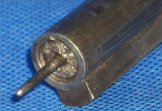
Photos 1.3a and 1.3b, yes? (Post #1)
jmoore
06-18-2012
And here's yet another link to a bolt with a broken cocking piece guide tab. Complete with a good failure analysis on Post #12:
No.1 MkIII Bolt Tab near cocking piece broke
Thanks, RobsTV.
Here's a repeat of Photo # 1.3a showing the area in question:
jmoore
01-17-2013
Here's a link to a thread showing a Savage with a badly mauled bolt head guide. Somewhat unintentionally shown on artyldr01's part, but it's a great example. More photos on his thread:
Savage No 4 Mk1/3 with red paint?
tiriaq
01-18-2013
With respect to the sheared off lug in the bolt's cocking piece cam track - if the cocking piece is placed in half cocked position, and enough force is applied to the bolt handle in an attempt to open it, either that little lug, or the corresponding lug on the cocking piece will fail.
I have seen a number of broken off bolt handles on a variety of rifles - M98 and M96 Mausers, M700 Remingtons, in addition to Lee Enfields. If the bolt cannot rotate (rust on the bolt sleeve threads being the most common reason in the case of the Mausers and Remingtons), and if enough force is applied, the handle will snap. On the Remington, the handle may break mid shank, or the brazed joint peeled. On the Mausers, the bolt handle will be broken out at the root, taking part of the bolt body with it.