Thread: Plate for Machining No.4 Bodies
Retrieved: 06/05/2014
"How to make a useable sniper - Part 2" contains pictures of a plate used to hold No. 4 bodies square, for machining and engraving.
Having recently experienced a "gunsmith" stuff up the mounting of pads on one of my rifles, I am wanting to duplicate the above plate.
I have unsuccessfully searched for dimensions.
Assistance in helping me find/determine the dimensions will be appreciated.
Peter Laidler
04-29-2012
You won't find dimensions anywhere. Each of the big workshops would make hundreds of jigs for machining, welding, engraving, breeching-up and everything else you could possibly think of. It was just one used for engraving that held the body both square to and parallel and at the same time, parallel to the vice/pantograph jaws.
jmoore
04-29-2012
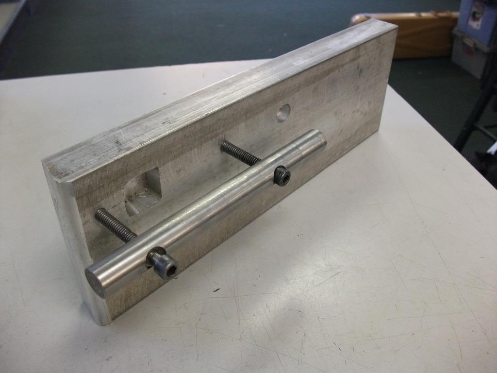
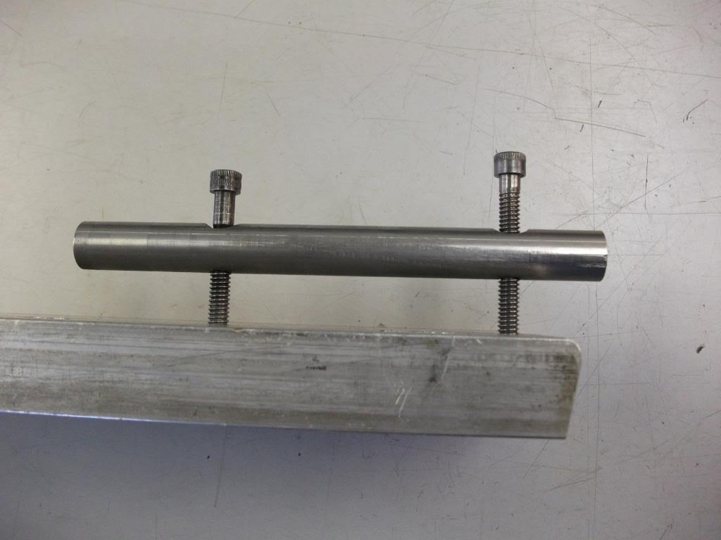
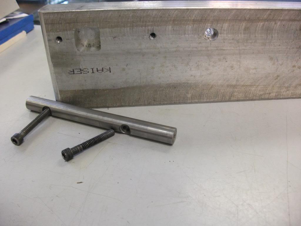
Pretty simple to fab up. Here's one I did some time back. You have to check that the works are square in both planes once the assembly is mounted in the vice, but it works fine as a basic holding fixture.

Longshaor
04-30-2012
Maybe I'm just thick as a whale omlet here, but you're saying that all the jigs you guys knocked up were just measured off the weapon being worked on & cut in the workshops on an as-needed basis?
Mk VII
04-30-2012
Back in the day they had plenty of machinists who were competent to design and make this sort of stuff, which was usually better than whatever tools the ordnance establishment supplied. Now I doubt anyone would be allowed to, as it isn't ISO9001, or whatever it's called now. Can't have units actually fixing their own problems, we have to generate $$ for defence contractors.
jmoore
04-30-2012
From what I've read of Peter Laidler's experience and research, the primary data were the bore and the rear sight axis pin hole. fore and aft placement of the pads was allowed a bit of flexiblity to ensure sufficient thread engagement of the rear pad. Apparently, Hollands adapted an old lathe bed for doing the milling and drilling work. Handy, I suppose, for the ease of using centers at either end. Photos of their device would be most interesting. There's an old lathe in storage that might get the same treatment just for funsies one day!
ETA1: (in dribs and drabs): To truly locate the pads off the bore axes, the muzzle end is pretty obvious- just use a bronze center. (Brownell's sells them in packs of five as they don't last long, but better damage to the center than the muzzle!) The rear end is a bit of a conundrum. To be exact, a range rod would have to be run in from the breech end, but would do nothing more than locate. Stabilizing the action body would be done by other means altogether. More support could be obtained at the expense of locating accuracy by utilizing a sort of chamber plug that wedges at the rear of the chamber. Least accurate but most stable (and what I've done for my repair plate) is to use a snug fitting action rod with a locating center at the rear of the rod.
The plate shown above was made for repair of loose pads, sheared spigots and such. (First use was to add dowel pins during a loose pad repair for an L42a1 that had a hard time with the night vision gear.)
[ETA3: The plate isn't really a locating devise. It's just there to stabilize the aligned assembly so it doesn't move whilst work is being done. The bottom of the action body is probably a manufacturing datum plane, but nothing references off of it for the purposes of scope mounting! At best it might serve as "c" or rotational axis locator, but if the sight axis pin happened to walk during manufacture, then "up" in the scope and "up" for the iron sights won't match.] ETA1continued: As far as doing a set of pads from scratch- Not yet! But I'd rather do them the way Hollands did- by forming the spigot and angle cuts after the pads were installed. (Shell mill cutter would have to be made for the spigot. I don't know if something is available that could be used or adapted without going the full "custom cutter" route, but that's an option, too!)
ETA2: Just a SWAG, but I reckon the rifle was installed on H&H's converted lathe and the spigot and rear pad were cut in less than fifteen minutes cycle time. Probably closer to 6-7 minutes to install, cut, and remove once they had the system tweaked.
paulseamus
05-01-2012
Thanks for both the picures of your machining plate and the accompanying notes.
Is is possible to post a picture of an action held in the plate?
I am sure that I have seen such a pic previously but a search of your past posts has been unfruitful.
To use a bastardised golfing term (NAGA) in the world of Machinists I am a bit of NAMA. (Google NAGA and you should work it out.)
Given that pre-qualifying statement, I believe that Holland and Hollands strength was to consistently produce durable zeroed rifles, in quantity, under the all the duress that the Axis powers could muster.
On the assumption that we are not trying to acheive a 15 minute cycle time, it must be possible to achive a similar result with a suitable lathe, milling machine, the correct techique and high degree of craftsmanship.
My personal preference is to to fit and mill the front pad from a base casting and the rear pad from flat stock, as per the H & H process. It's not that I have an issue with reproduction pads, it is just that the correct process offers a higher dregee of legitimacy.
I have a buddy who runs a large Automotive casting plant. He can cast the base front pad, i've just got to work out how to convince him to do a batch.
Not been a machinist, I need guidance as to a source for a suitable sheel mill cutter.
jmoore
05-01-2012
Originally Posted by paulseamus
Is is possible to post a picture of an action held in the plate?
I am sure that I have seen such a pic previously but a search of your qpast posts has been unfruitful.
Unfortunately, there's no "in use" photos, as most of that work occurred
before the fairly recent addition of a digital camera. You are probably
remembering the last pad repair, which managed to not require the plate, being
a simple screw replacement and resoldering.
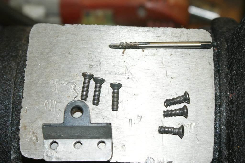
The partially sheared screw shows why one ought to just go ahead and replace them!
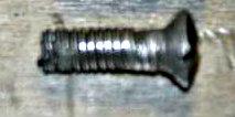
But, as to your request, due to the recent move, it may be a while before the plate "resurfaces"! Two new roll-around toolboxes will help, but everything is still in boxes as we move equipment and build storage space. If you don't mind, it'll probably be just a stripped spare regular old No.4 Mk.I* barreled action for demonstration purposes.
Originally Posted by paulseamus
Not been a machinist, I need guidance as to a source for a suitable shell
mill cutter.
I'm going to speculate that there's nothing out there you can just order from
stock, but I could be happily wrong!
There's various options. Hollowing out a regular endmill might do, but it's less than theoretically optimal, as the face is slightly relieved toward the center. Thus the bracket would only make contact directly adjacent to the spigot.
A spotfacing or counterboring tool is a better choice, I think. Fairly common aviation type cutting tool. They typically have a small pilot hole for changable guide bosses, enlarging that hole is the challenge. EDM would work, but might not leave a good finish on the sides of the spigot. Maybe EDM roughing of the hole with a cleanup grind or maybe a tiny carbide boring tool. This is the likely route I would take.
Another possibility is something called a "Stud off" cutter. Generally a thin walled end cutting tool for removing swaged studs that retain brake discs or drums. The drama being the "thinwalled" part! Haven't fully investigated this option.
ETA1: Some more: If you have heat treat, then you could make a single point cutter from tool steel bar stock. Very possibly how Hollands did it! ETA2a: But be prepared to either make several, or having a means to fine tune the spigot diamater after heat treat. If required, you are back to the dramas associated with the earlier options.
Possibly the most flexible option would be to adapt some carbide insert tooling for the job. A Kennemetal NRD3125LK insert has possiblities, but getting the back relief corrected for the tight radius would require some mods. The real bother comes from making an insert holder with just the right geometry. And adapting it to a boring head.
Probably a small pointy insert on a sweep type boring head (or "facing boring head") would be easier, if you don't mind the expense of the "SWBH". Wolhaupter made a very nice one!
ETA2: As for generating the radius or chamfer on top of the spigot, use your imagination. Not a super critical area.
tbonesmith
05-02-2012
All this work and tooling cost lots and lots of money and time. I have been putting together this type of kit for some years with regular reasonably large financial outlays, and I still have thousands to spend. Plus the ongoing time factor. I thoroughly understand the motivation to do it yourself, learn it yourself, and in every way "make it your own", but if you really look at it in the light of day for what it is, I think this project would be better served by you finding a real No4T body with pads, and building on that.
As I said I completely understand your motivation here and I don't mean to be discouraging, but don't underestimate the size of the learning curve if you're starting from scratch.
Peter Laidler
05-02-2012
I'm glad that you said that TBone... making these body holding etc etc jigs is one thing for a huge workshop doing this stuff every day but for the home workshop, it just somehow looks or sounds like an effort to production line or industrially convert No4T bodies. We already have a good example of a home grown abomination elsewhere on the site that looks as though it was done without the benefit of a body clamp (and even sharp tools now that I think about it...)
Nope... I'm not so sure...
I've put my steel helmet on and await the incoming mortars
trooper554877
05-02-2012
The person asking for the info has no intention of going commercial. He is asking because he has been let down by a supposed expert gunsmith who totally buggered up a repro conversion costing not only the conversion but the rifle itself. no -one wants a buggered converted No4 He is obviously thinking of doing it himself or getting someone to do it for him who he can trust.
It's OK for you people who can afford a genuine No4T at the rate of around 4-8 thousand dollars here in Australia.
I thought through the generosity of Peter laidler providing an instruction for a suitably minded person to be able to attempt the process, that asking for the details of the plate to eradicate any probable errors would have favourably be looked upon. Obviously not.
Just for info, I have done one of these conversions myself which worked quite successfully. I can fully understand someone wanting as much guidance, advice, tricks and the benefit of some of the most highly regarded expertise from all over the world here on this forum.
jmoore
05-02-2012
My interest is not in actually creating ersatz "T"s, but rather in building an understanding of how it was originally done. Supposedly there's a photo of the converted lathe somewhere, but as it has yet to surface, it's been mostly a mental exercise. The plate in no way attempts to replicate Holland and Holland's approach- quite the opposite! It's merely a holding fixture for repair work. As a production tool it is wretchedly inefficient.
(BTW, we used to spend hours and hours studying Curtiss P40 production line photos for the express purpose of generating tooling that could be used to produce fuselage and wing assemblies that would be interchangable and indistinguishable (minus the tiny Curtiss identification and inspector's markings) from the original. That study DID pay off. Recently talked to my old partner in insanity and he's back building Curtiss products like mad. Folk ["collectors"] in this case are happy to have new flyable gear- a completely different mindset- and rightfully so!)
With the availability of reproduction scopes, brackets, etc. it seems reasonable to build new workhorse shooters with the understanding that some nefarious types will try and pass them off as collectibles. We can't stop the swindling, but I'd sure rather folk wear out ersatz "T"s in competition, etc, and save the real thing for minimal use so folk in the future will have something left. But without proper set-up, the ersatz version won't perform as well as they could otherwise.
Brian Dick
05-04-2012
Charlie, They are fixed by a jam nut into the charger bridge and screws through the rear sight axis pin holes. Solid as a rock. Because the charger bridge was never intended to be a fixing point for collimation and they do vary, I always recommend a good set of steel, windage adjustable rings like Millett. It makes it a snap to collimate the telescope to the rifle bore with the full run of left and right deflection..
jmoore
05-04-2012
Originally Posted by Brian Dick
I always recommend a good set of steel, windage adjustable rings like Millett.
It makes it a snap to collimate the telescope to the rifle bore with the full
run of left and right deflection.
Does Burris still make the rings with the spherical offset inserts in varying
increments? I've used those for several applications to optically center
scopes in both elevation and windage. I've heard some folk dislike 'em, but
they have done an excellent job for me. Liked the system well enough to put it
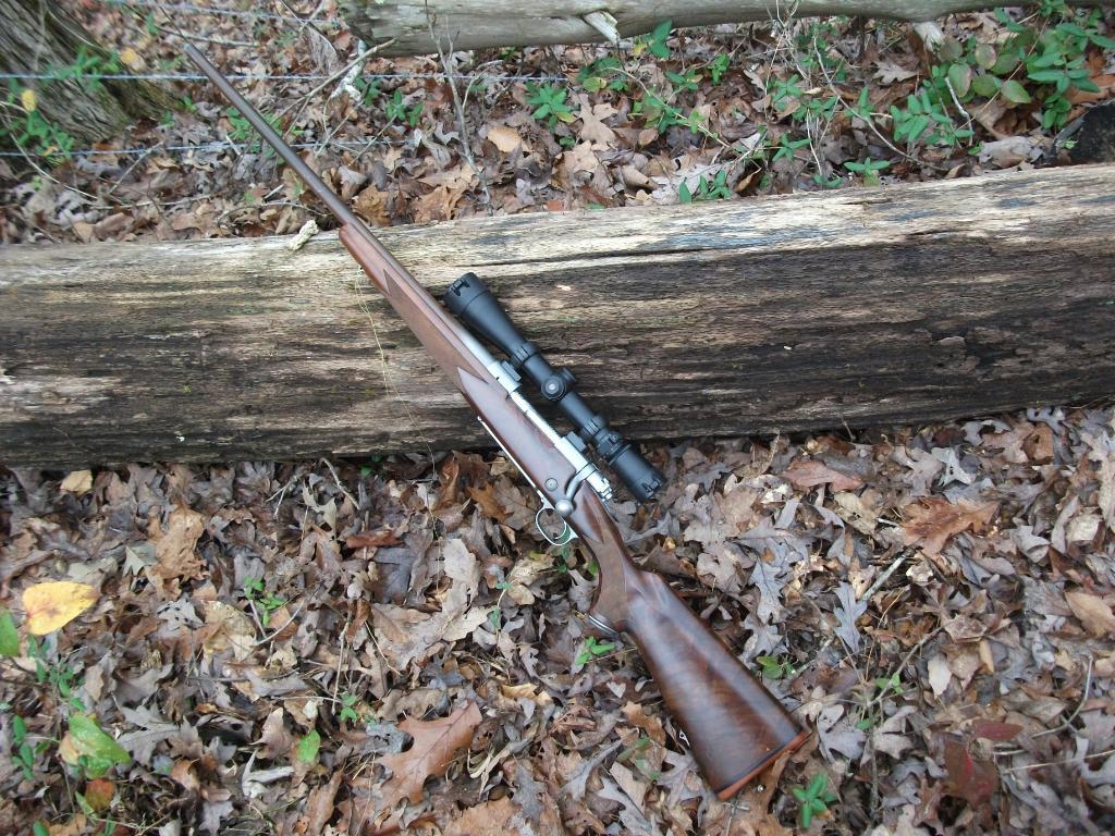
on some expensive and extremely accurate gear, like the below. ( Winchester
Ultimate Classic Stainless Model 70 LH. Note that in this instance I selected
30mm dual dovetail rings. No other way to mechanically zero the scope than by
selecting and rotating the inserts! Rock solid for quite a few years now.):
paulseamus
05-05-2012
Gosh... it's a couple of days since I have logged on and wow it seems that my integrity has been both questioned and defended- (thanks Ned).
Perhaps I should explain why I posted my request.
I have a had a No.4 ruined by having the pads fitted incorrectly. Not by me but by a "professional" gunsmith who specialises in building accurate sniper rifles.
So I am now a bit poorer and a bit wiser.
My request for the dimensions of the plate, is so that i can get one machined up to ensure that the next gunsmith that I use has the correct tool to ensure that the pads are correctly mounted.
I am a firm believer that you do need the right tools for the job coupled with an skilled set of hands to use the tools. Ironically Peter, i am in the business of pulling engines out of cars, fixing them and putting them back, so I understand your analogy.
Whilst I would like to experience having a go myself, I don't have the skills and our local laws prohibit private gunsmithing.
The desire to cast and machine a set of pads, is to keep the process as true as possible to that of H & H. It seems a bit incongruous to fit a DRP mount to a set of Numrich pads.
The reason for wanting to build a replica rather than buy a genuine is not simply cost.
I do have my eye on a genuine No.4 (T) that is in stock at BDL. Even made calls during the week to a local dealer to get a quote on the cost of importing, but then a few unexpected bills arrived, so those plans are now on hold for a short while. (Brian, I will contact you when the required funds are freely available)
Regardless, I want a Genuine No.4(T) because I want one . It will be shot infrequently.
I want a replica No.4(T) and a replica L42A1 to shoot regularly in competitions. With no worry about damaging their historical value and no worry about rebarrelling them if and when required.
It's never been about making fakes. I know a lot easier methods (and more financially rewarding) of trying to make an honest living.
To close, I do repect both the passion and the wisdom that you all bring to this forum.
Accordingly I have read all posts in the spirit that they were hopefully intended.
Where to next, I am not sure. Might have to read those Peter Laidler books and guides a few more times,
PS does any one have the dimensions of the plate for machining...
jmoore
05-05-2012
Perhaps I wasn't clear earlier. All the plate has to be is flat on top. And clear the butt socket in back by some amount. Hog out a relief cut that's bigger than the boss under the receiver ring and again under the rear lump. Add some clamping capability somewhere, and you're good! I pretty much eyeballed the whole plate. All of my attention was on the round clamping rod. Diameter of it can be determined by direct measurement of the action body's raceway.
Flat on top. Everything else is discretionary.
jmoore
05-16-2012
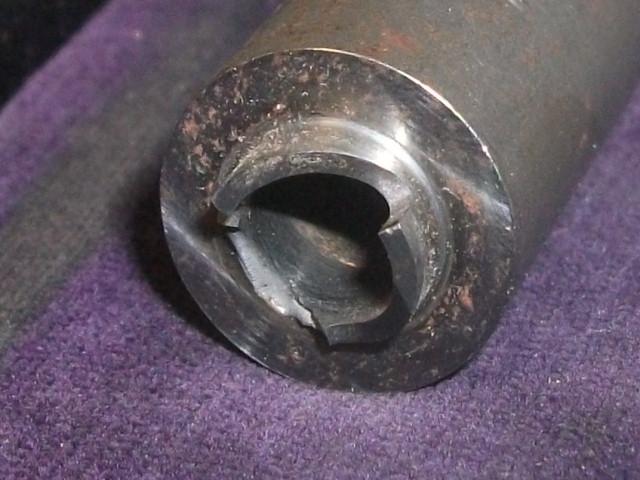
Here's a broken example of the type of cutter that is likely close in concept to what was used by H&H to shape the the OD and face of the mounting spigot:
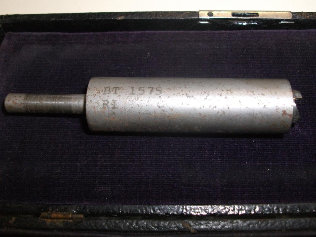
Unfortunately, I don't even remember from whence this tool came. I've had it knocking about for probably twenty or more years.
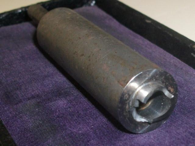
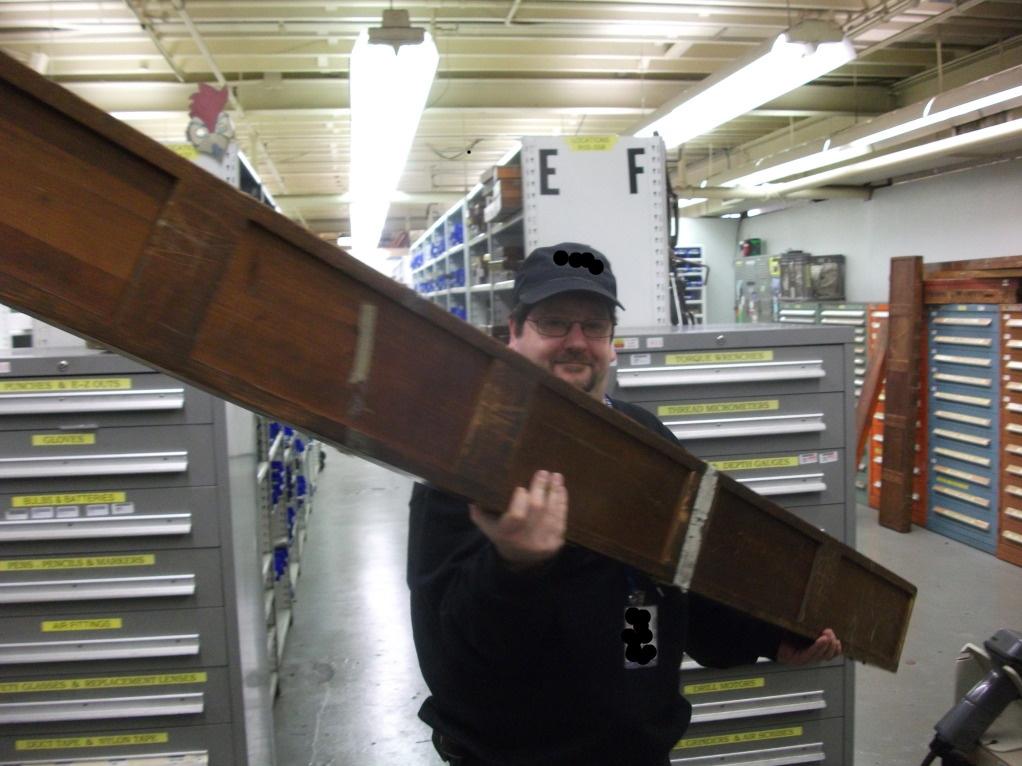
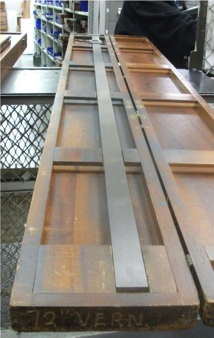
And here's your calipers to measure work in progress:
Peter Laidler
05-16-2012
JM and pauseamus, it's a shell mill cutter and they're quite common from your engineering suppliers. But during the L42 days you'd occasionally get the spigot torn off the front pad during recoil. So we'd bore through the known datum hole from the rear of the pad and manufacture a new spigot part, insert from the front and braze in place. I think I mention this in the little book somewhere. But it was a quite common failure and and easy fix. Maybe this is a better option than shell milling the spigit in the first place.
Brilliant set of calipers... Calibrated biannually too I expect! Is that your tool store in the background?
jmoore
05-16-2012
A bit different format than what we colonials call a shell mill cutter, as there's no cutting edges on the OD. (I have plenty of those, but no photos.) Usually referred to as "stud off" tools, when anyone has a clue what you are talking about- but most folk just look at you funny. Which is why I've kept that broken one- just in case I ever really have to get another.
I agree that the separate spigot method seems easier. Small counterbore on the back side of the pad and a corresponding major OD on the spigot shank. Light press fit from the right side, etc.
Yah, that's our well equipped tool room at my "real job". Always not quite what you need rather later than when you need it. Which is why my personal roll-around tool box at work is such a tank! But it's better than than having to have three as I do at my own shop- and still not enough room to be organized. Machinery's "cheap" (but requires bigger individual chunks of cash). It's the tooling that drags you down...
jmoore
05-18-2012
Severe anorak alert!
Here's what we wild colonials call a shell mill cutter:
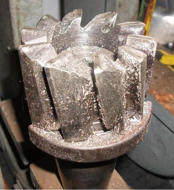
Note the cutting teeth on the OD. Also the face is generally not flat, much like a standard end mill- it's "coned" slightly in order to gain some chip clearance and to reduce friction. Only specialty tools like counterbores/spot facers and such have flat faces.
So converting a regular old end mill won't be optimal!
The "stud off tool" (shown earlier in Post #33) on the other hand is used to remove studs like this one:
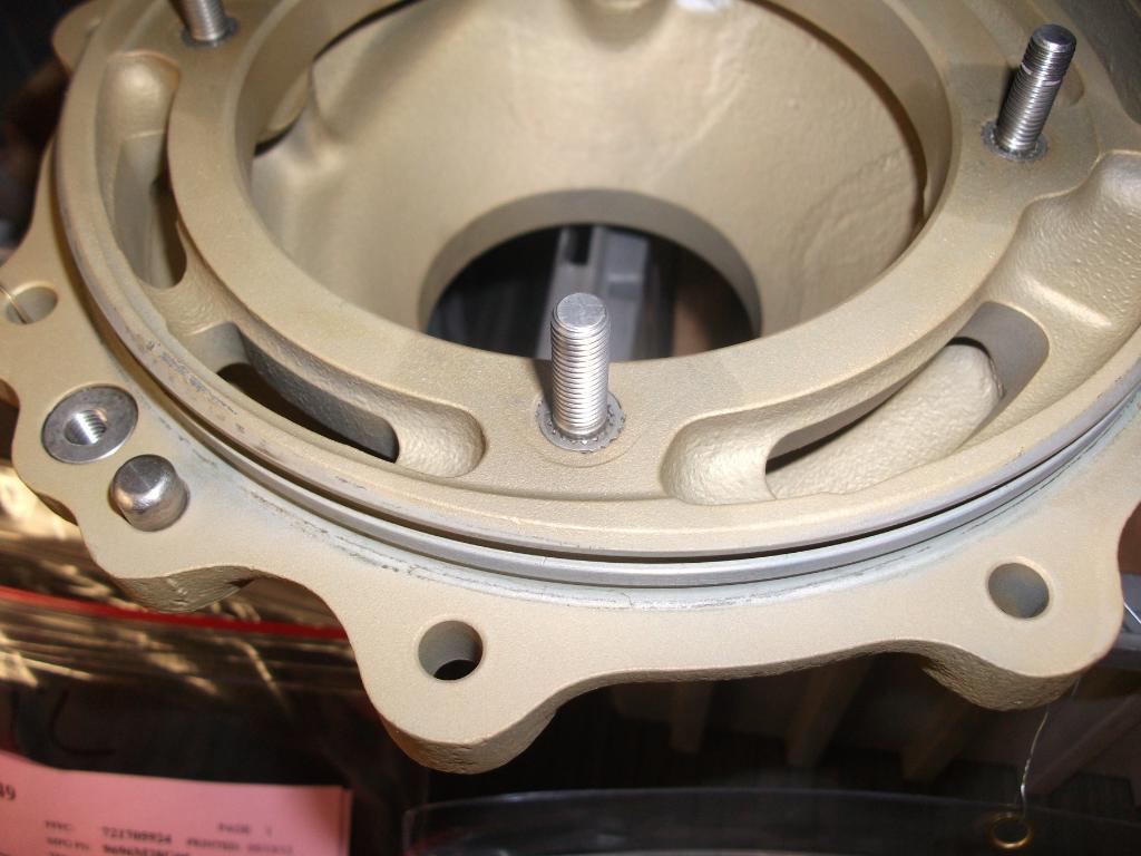
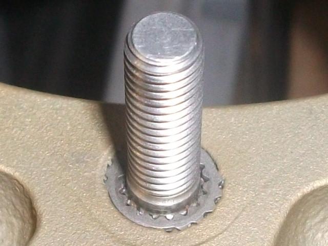
Rosan locking method used to retain screw in studs. The cutter removes the bulk of the toothed ring without damaging the part and (usually) stud.
There's also swaged stud flange removing tools, most commonly found retaining drum brakes. These cutters usually have well beveled cutting faces.
The drama with the stud removing tools is that they're too thin walled to be useful for making a spigot forming cutter. I'm thinking that a counterbore may be the best tool to modify if one insists on doing this job the "H&H way". There may be more coming, but this computer is about to self destruct. Can't hardly edit photos, or even stay on line reliably!
jmoore
05-19-2012
If you want to modify an off the shelf tool for making a spigot as discussed above, here's the likely suspect:
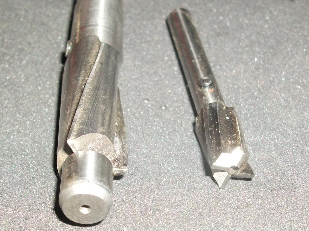
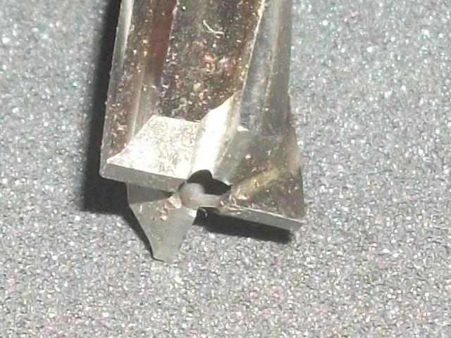
Made specifically to produce a flat face, a counterbore or spot facing tool usually has a small hole in the center for a removable pilot. Enlarge this hole and grind the OD to suit.
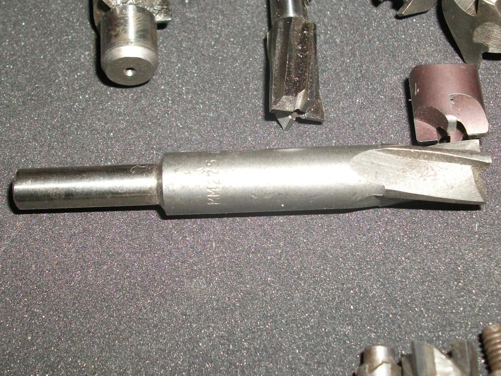
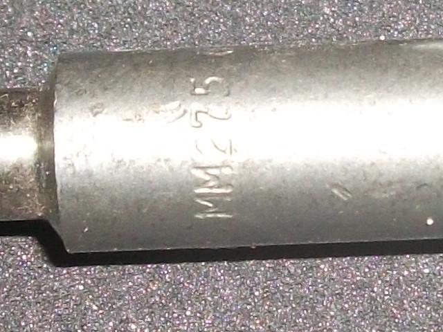
Another one. Maybe the ID number will help. I haven't really paid attention, as we used to have a local used tool vendor with buckets of 'em. We would just pick through and get what we needed and then some!