T350 Rebuild
In an incautious moment I'd offered to rebuild the transmission in a friend's
race car. He finally said the time was nigh...
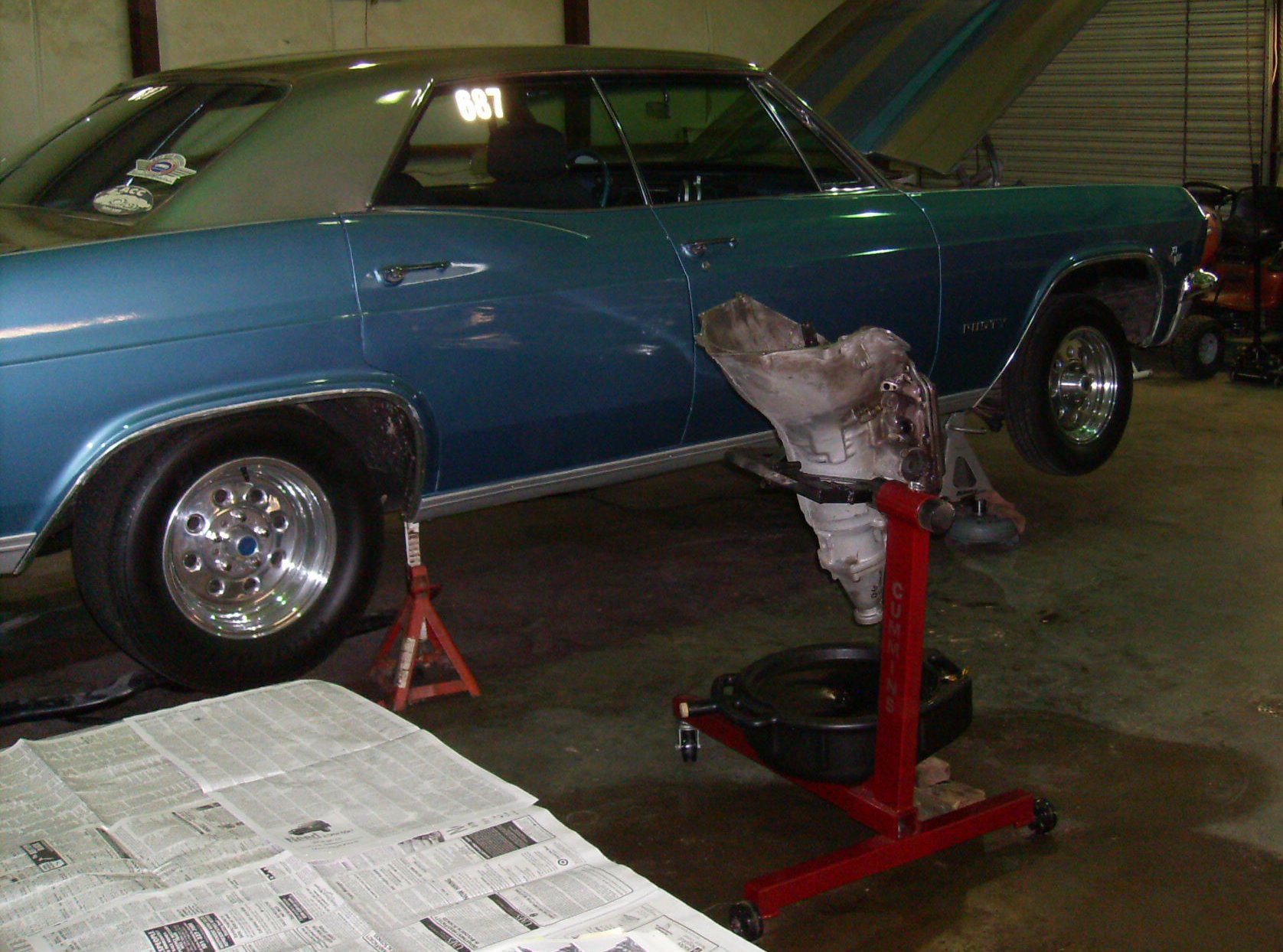
Tommy's '65 Impala. It made 605 passes down the strip (he kept all his
timeslips), most with a small block 400, the last few with a 396 big block.
Tommy said the transmission wasn't slipping, but it was shifting slowly. The
fluid looked and smelled okay, but with the new big block he wanted to go
through the transmission.
He was running a Turbo-Hydramatic 350. Someone else had rebuilt it before.
There was nothing broken, it was just getting tired.
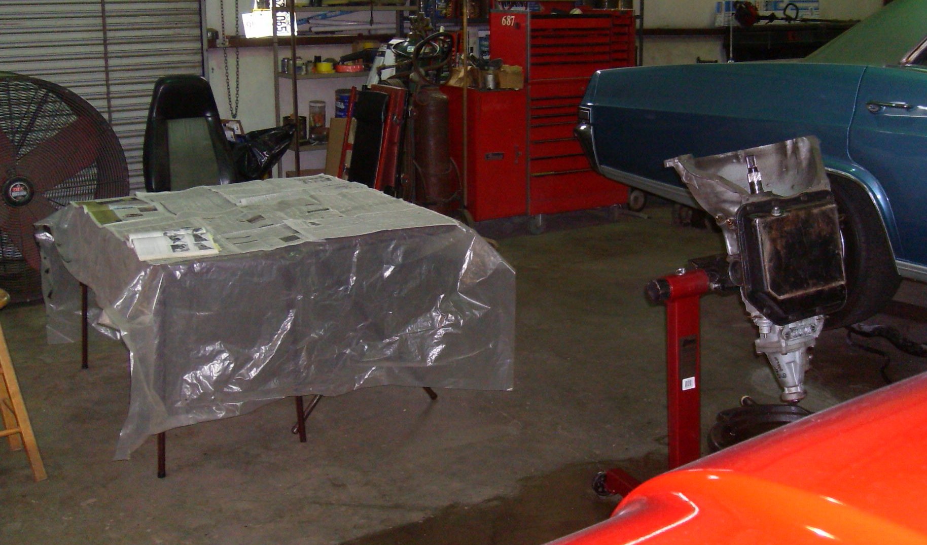
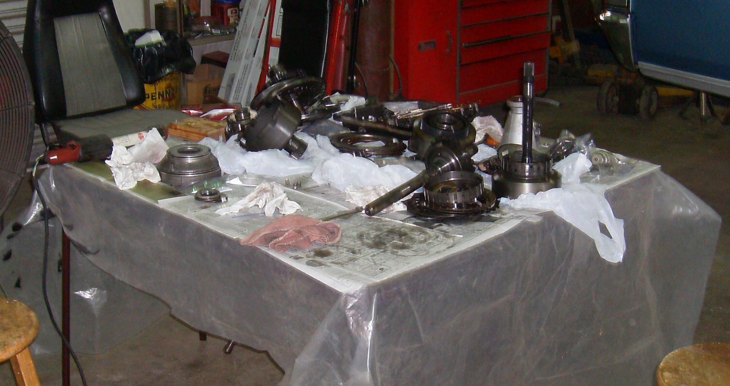
My good transmission adapter had gone walkabout, so Tommy borrowed one from
someone else. He set up a couple of card tables with plastic and newspaper.
The Book is already open on the table. We're using Ron Sessions' "Turbo-
Hydramatic 350 Handbook." I'd done several T350s, but the last one was six or
seven years before.
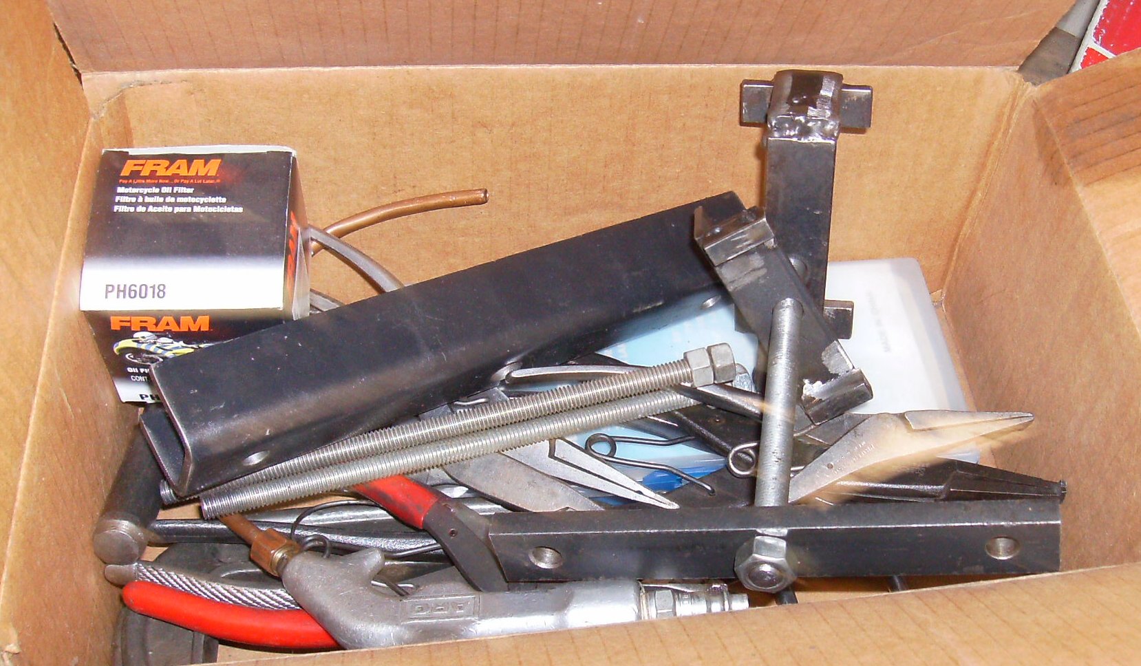
One box of tools - homemade spring compressor, ground-down snap ring pliers,
pump puller bits. I'd made all the tools for earlier builds.

Slide hammer, 1-2 servo cover lever, long driver for installing rear case
bearing.
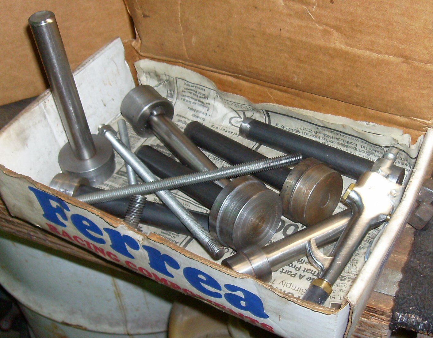
Bearing drivers, rubber tipped blowgun for air checks. Many people don't
replace the bearings, but I figure "if you're in there that deep, what's
another $15?"
I think Tommy expected a supervisory role, but I handed him a wrench and sat
back to direct. It's a "hands-on learning experience!"
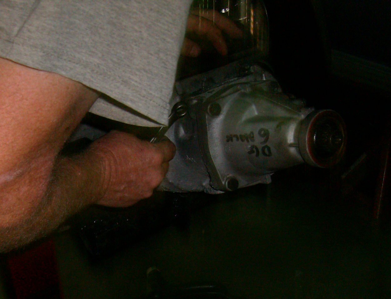
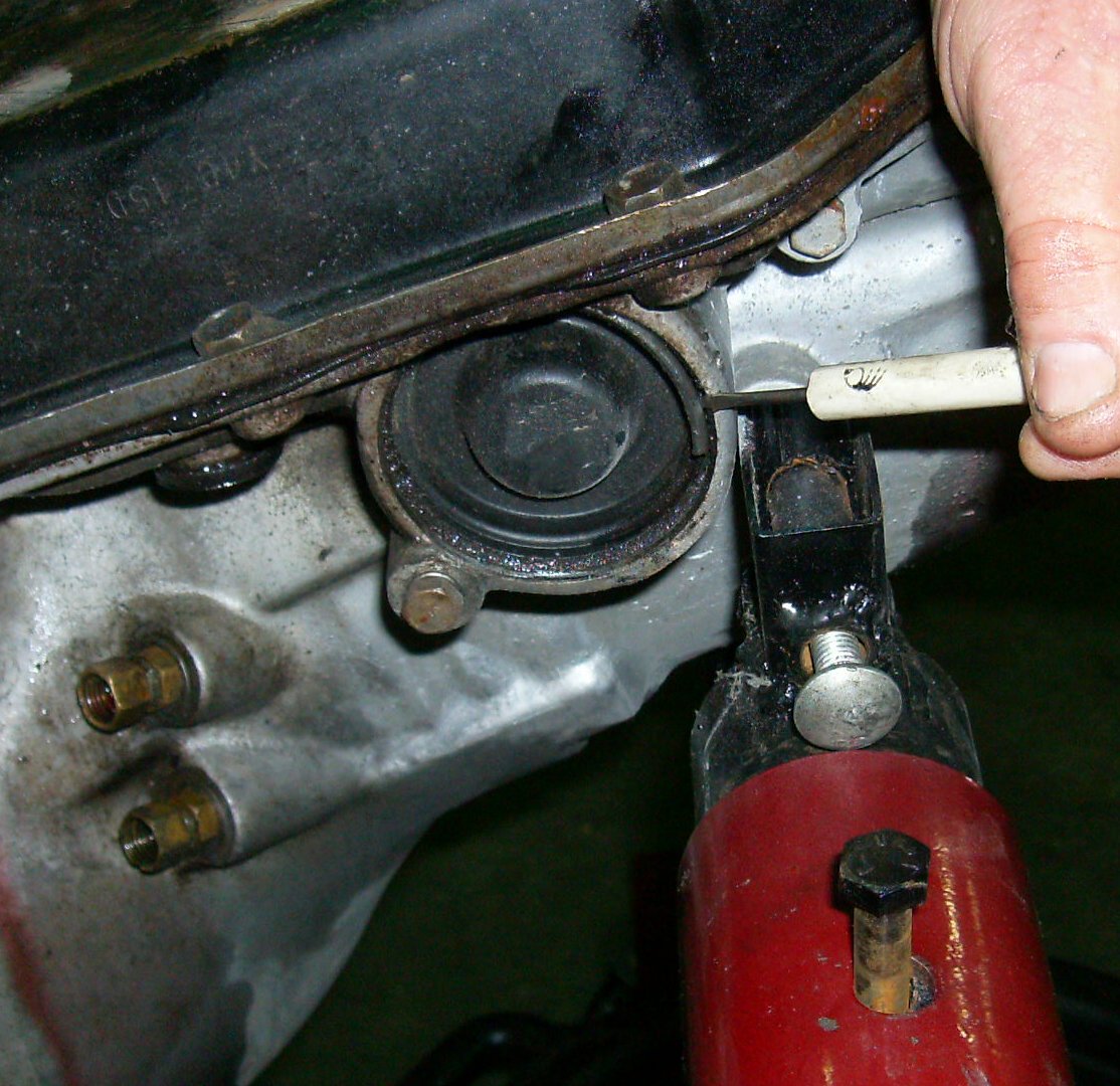
The first step is to remove the bolt for the vacuum modulator.

Pull the modulator out. It has an O-ring and may be in there pretty tight.
If you have to pry, use a wide screwdriver and take care not to dent the
housing.

Modulator valve slides inside valve body. Don't tilt the transmission or it
may fall out and get damaged.

Slide the valve out carefully.
The governor cover bail snaps into a depression in the bottom, hooks into a
hole on the top. Some later transmissions had the holes but no bail.
The bail is quite stout and can be a bear to get off. Don't ding the cover
while levering; if you do, it may drag on the governor and cause odd shifts.
The servo cover is a press fit, much like a big wheel bearing cover. It can
also be a bear to remove. You can only get to part of it to drive it off.
Work it off carefully; it contains oil when the engine is running and will
leak if you damage the cover or the machined seal surface. The sheet metal is
thin and easily damaged, and they're not a service part any more, so be really
careful.
Slide the governor out. Don't drop it - it's a precision device and "replace
as assembly." And priced to match, of course.

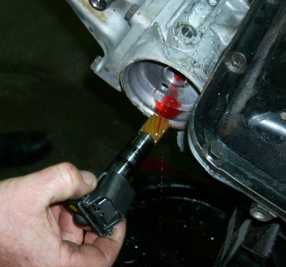
Take the bolt out of the speedometer adapter retainer.

Slide the speedometer adapter out. It has an O-ring and may be tight.
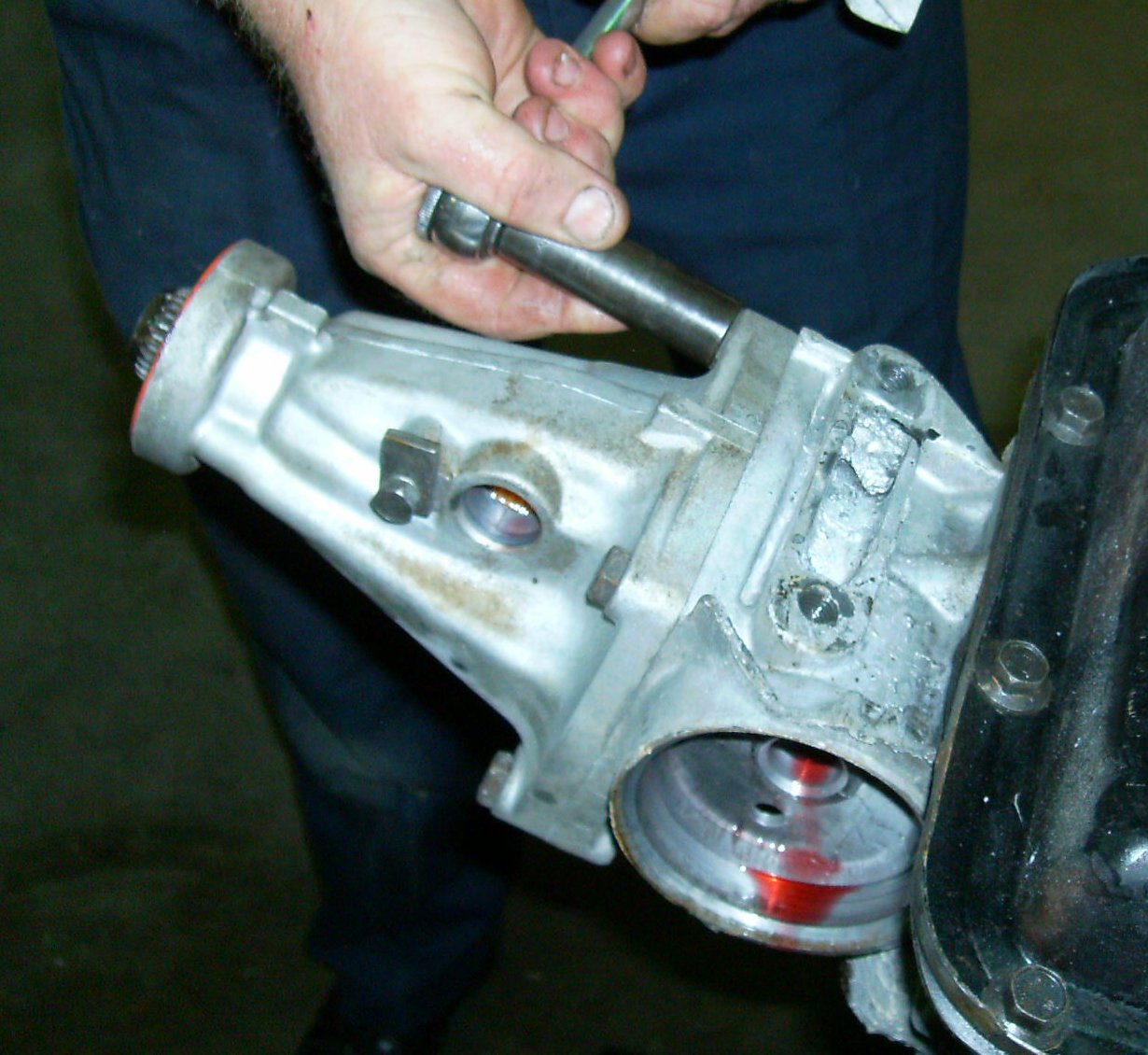
Remove tailshaft extension. If the bolts are corroded into the aluminum they
may take quite a bit of torque to remove. A propane torch can be helpful if
so.
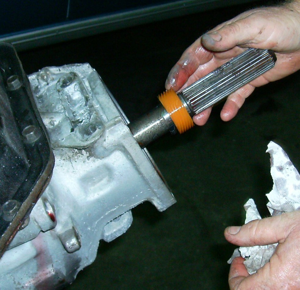
Remove speedometer gear. On the bottom left of the gear you can see a spring
steel loop. On the right, you can't quite see where the loop has a bent end
that holds the gear. Press the loop down with a screwdriver, wrap the gear in
a shop rag, and yank. There's a special puller tool, but the gear will
usually come off by hand. You can use an open-end wrench and a hammer to
drive it off if yours is tight.
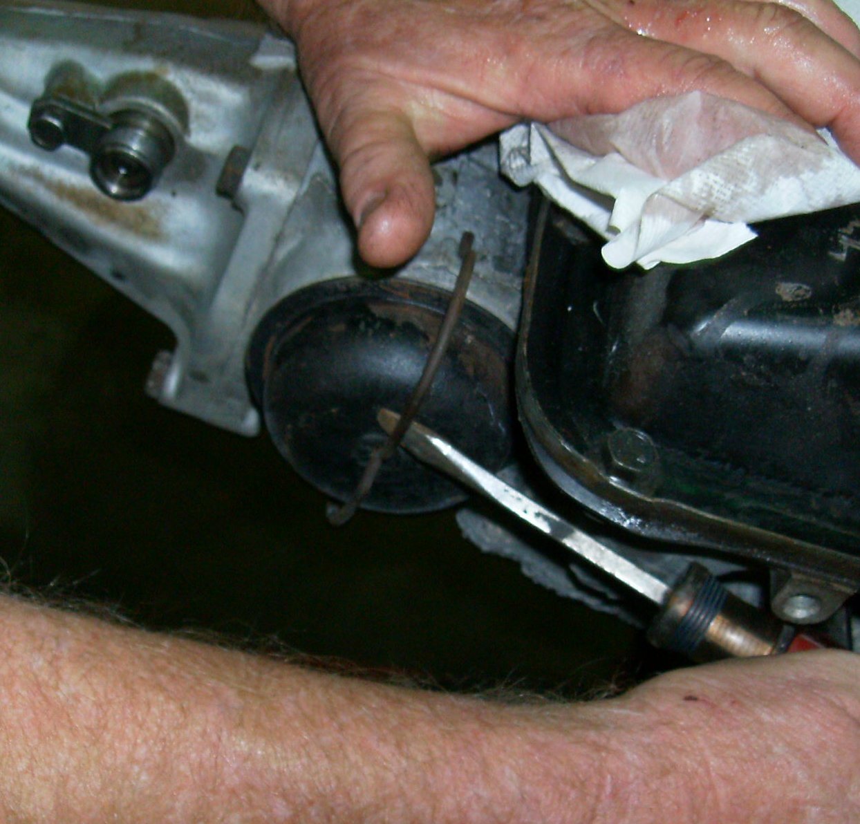
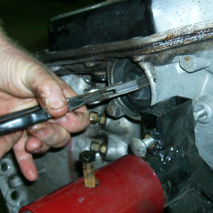
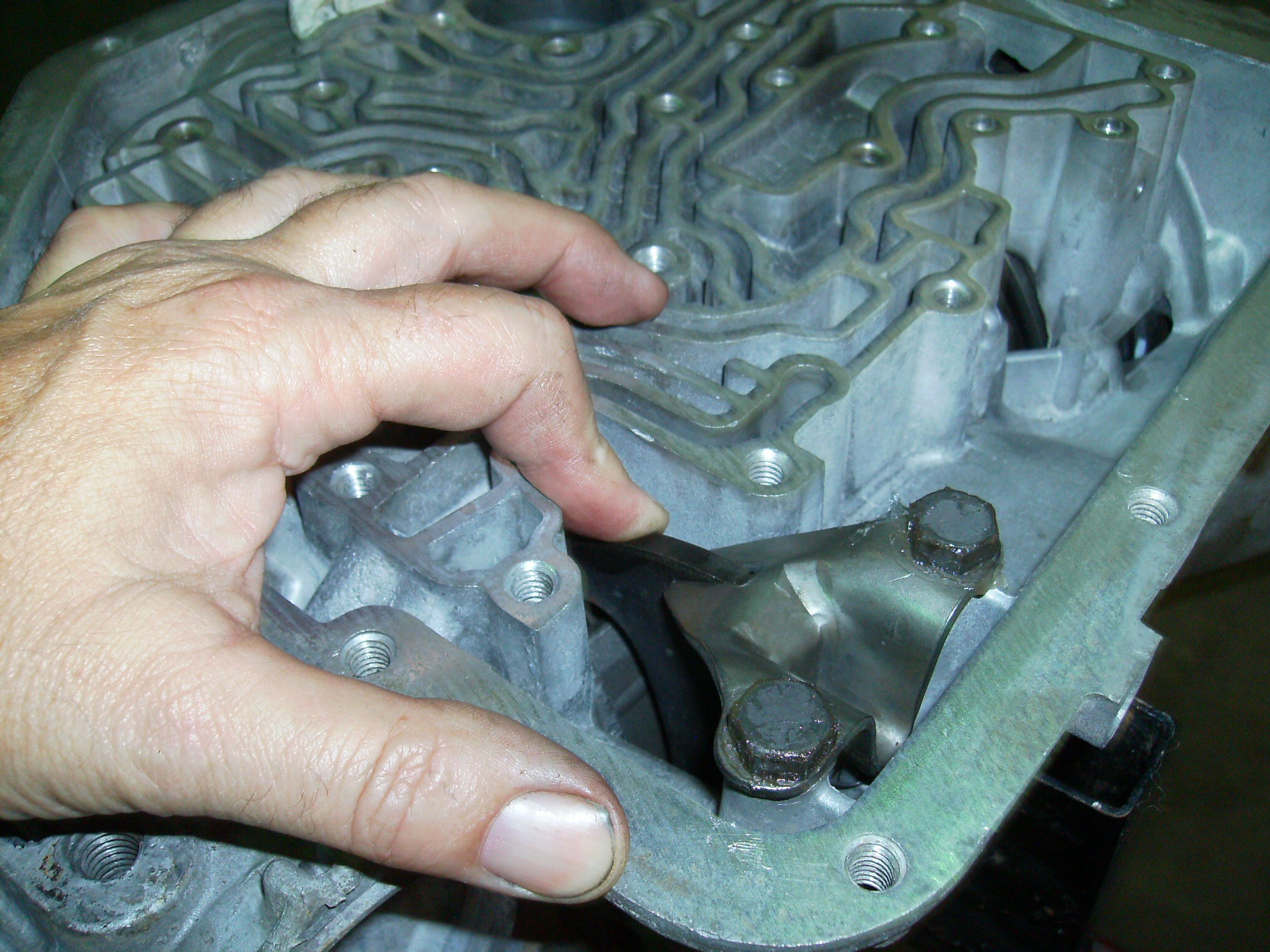
Fat, round wire ring holds the 1-2 servo cover in place. Just above the
screwdriver you see a small hole just over the 3 o'clock position. Use a
punch or flattened nail through the hole to pop the ring up so you can get
behind it with a screwdriver.
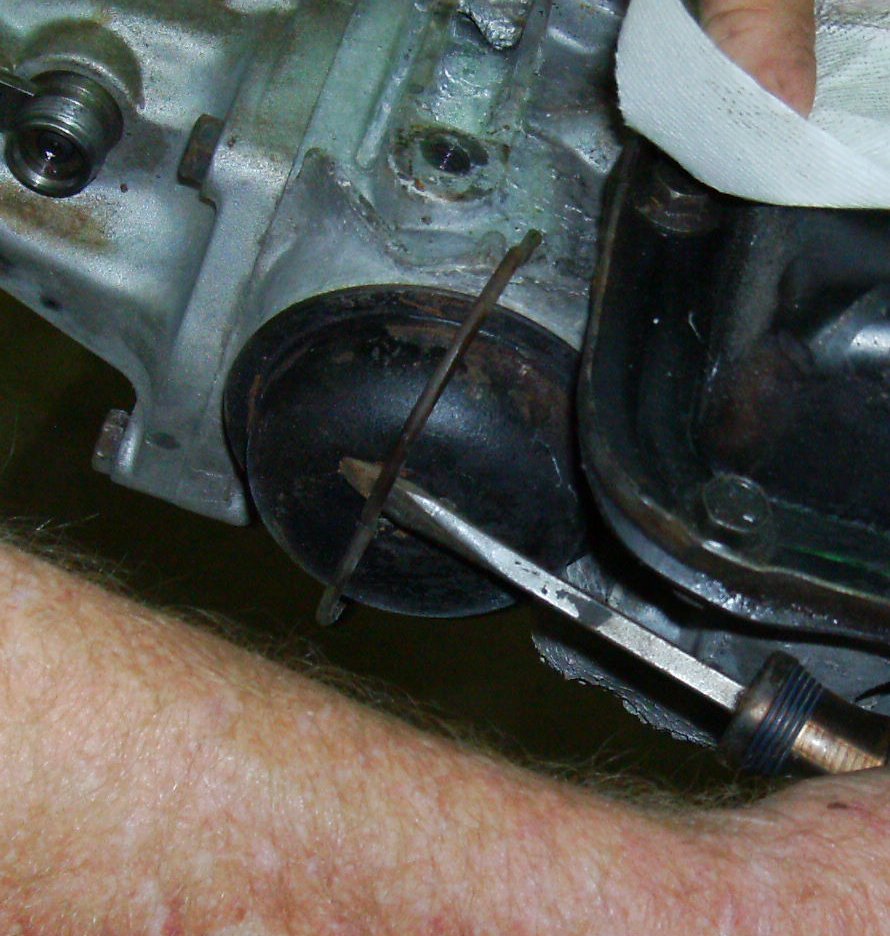
See how the end of the spring is near the round hole, just above the
screwdriver blade? That's how you want to reinstall it later. If the ring is
clocked differently it can be very hard to remove.

The ring is pretty stout; sometimes two screwdrivers help.
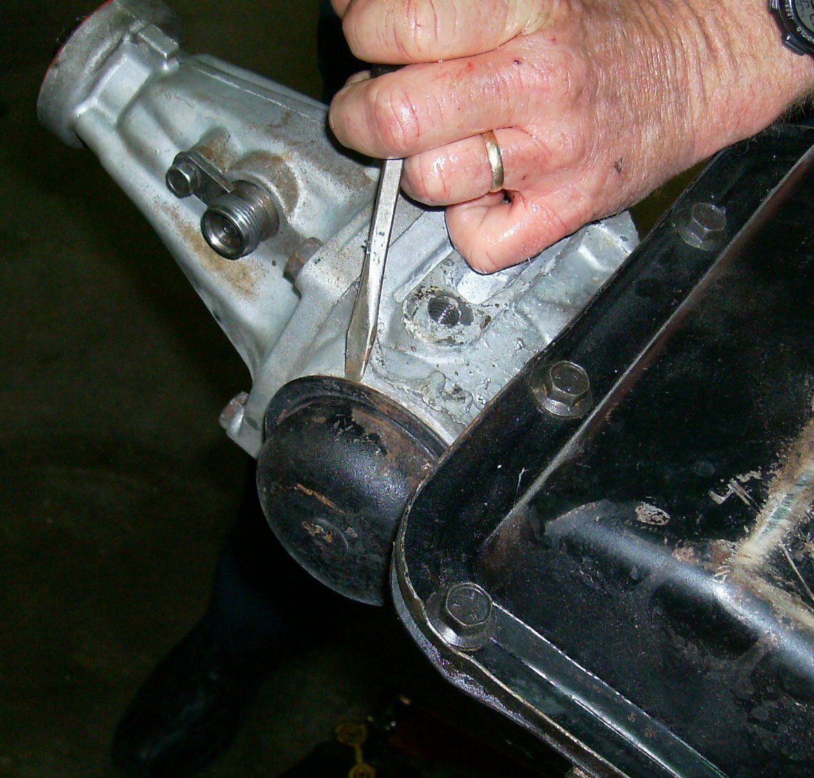
Normally there's a fat spring behind the servo piston, pushing out on the
cover. This transmission had a shift kit installed and had no spring. You
may need pliers to remove the cover.
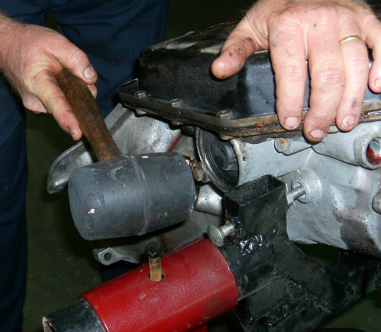
Sometimes you need pliers and a rubber mallet. Or dynamite.
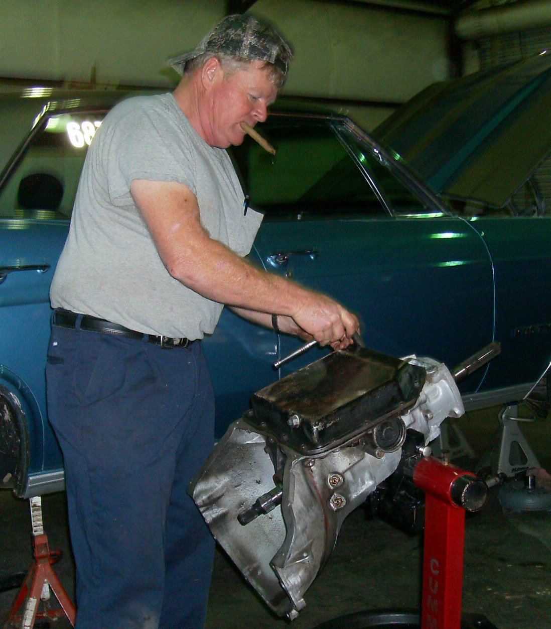
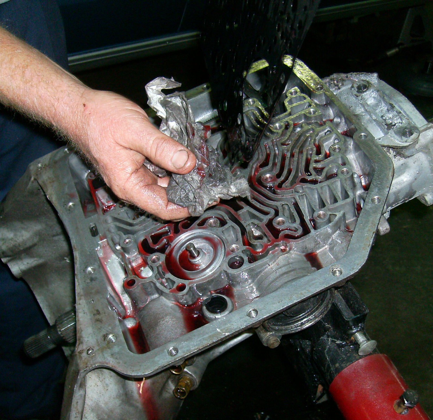
Now you can remove the pan. Tommy had replaced the fluid and filter several
times during preventive maintenance, so the inside of the transmission is
much cleaner than you'd normally see, besides not having being burnt or
exploded.
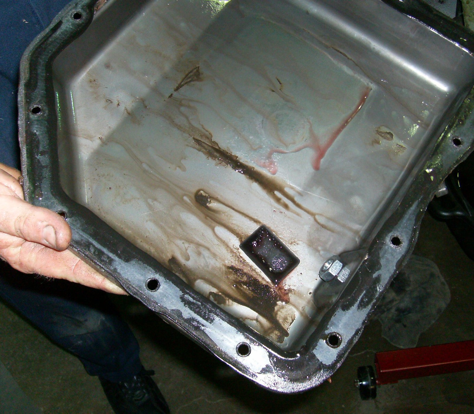
The fluid was changed a couple of years ago, but this is still amazingly clean
for a T-350.

Flathead screws hold the filter in place.
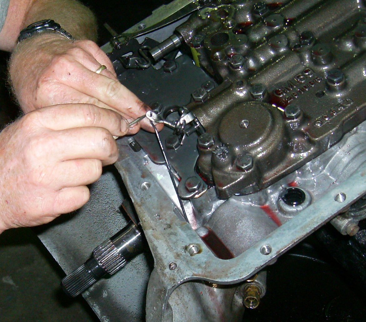
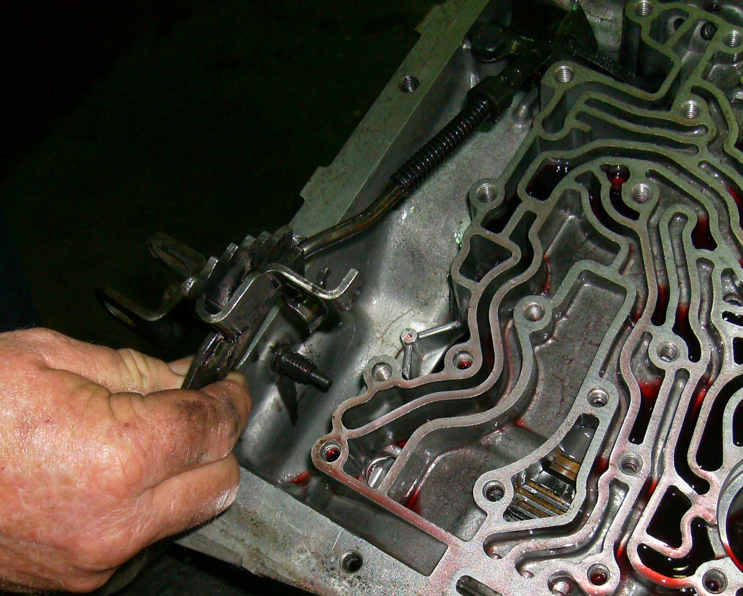
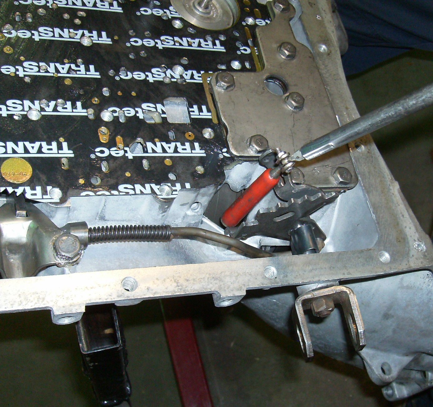
The modulator cable goes to the case where it hooks onto this wire that sticks
out of the hole. You have to pull the hairpin spring out to remove the sheet
metal rocker arm so you can get the wire off.

Now you can unbolt the valve body. Make sure it doesn't slide off the
transmission and crash to the floor when the last bolt comes out.
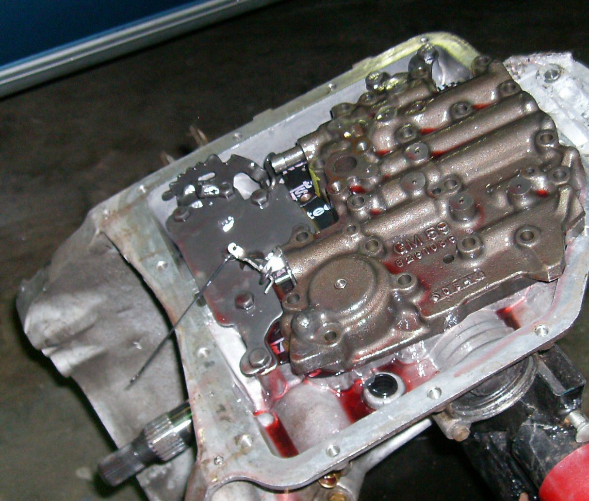
The manual valve (partly slid out on top) may slide out the rest of the way
and fall. Be careful.
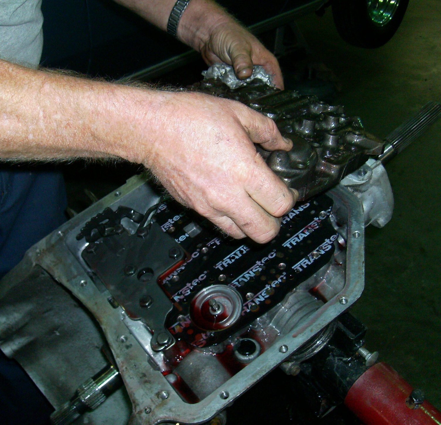
Lift valve body from case. If it is stuck, make sure all umpty-dozen bolts
are out and tap the body carefully with a brass or rubber hammer.
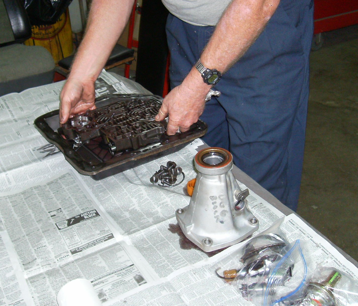
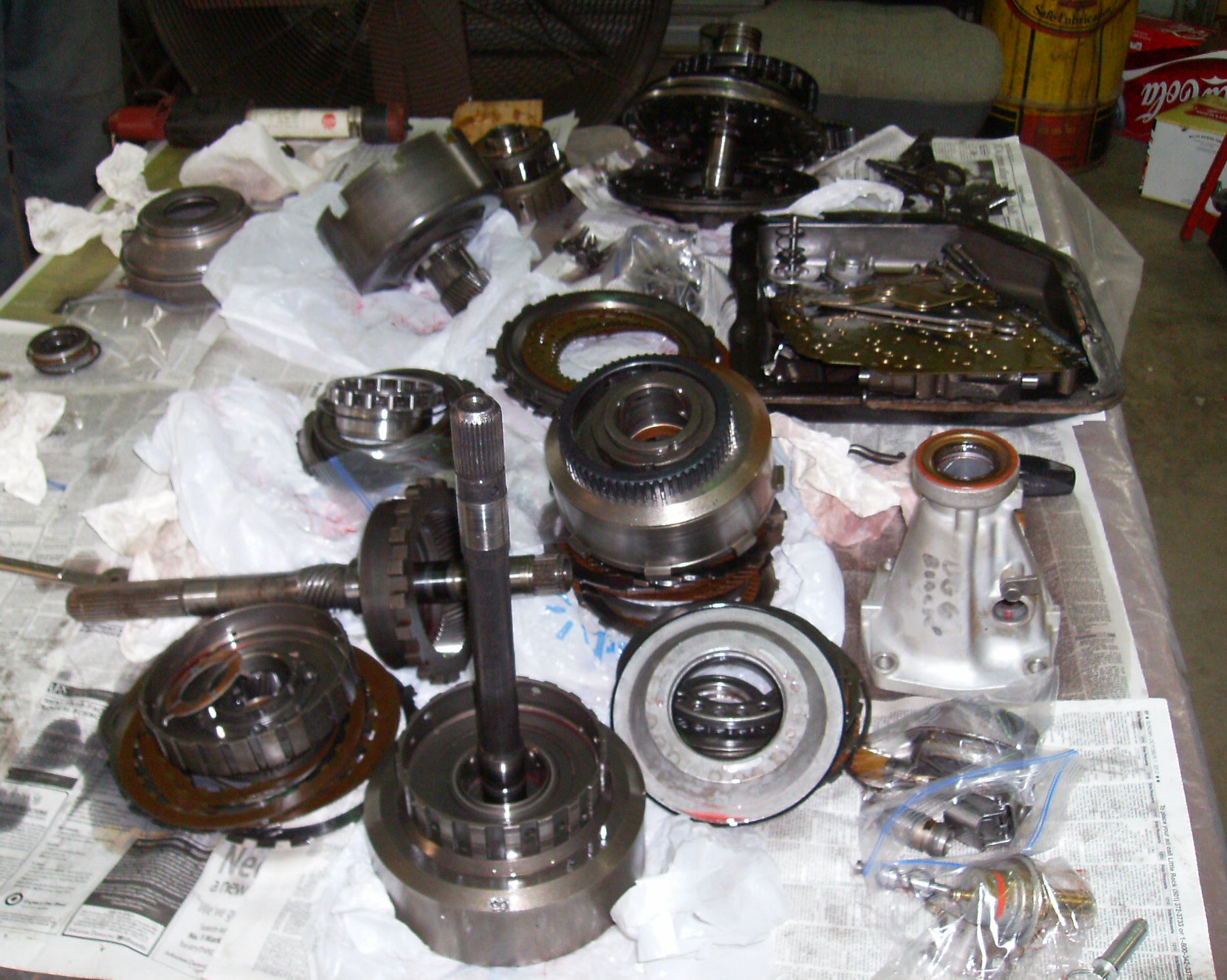
We put the valve body in the pan to contain the drooling oil. Both will get
cleaned later. Note how each subassembly has been bagged and laid out in
order on the table.

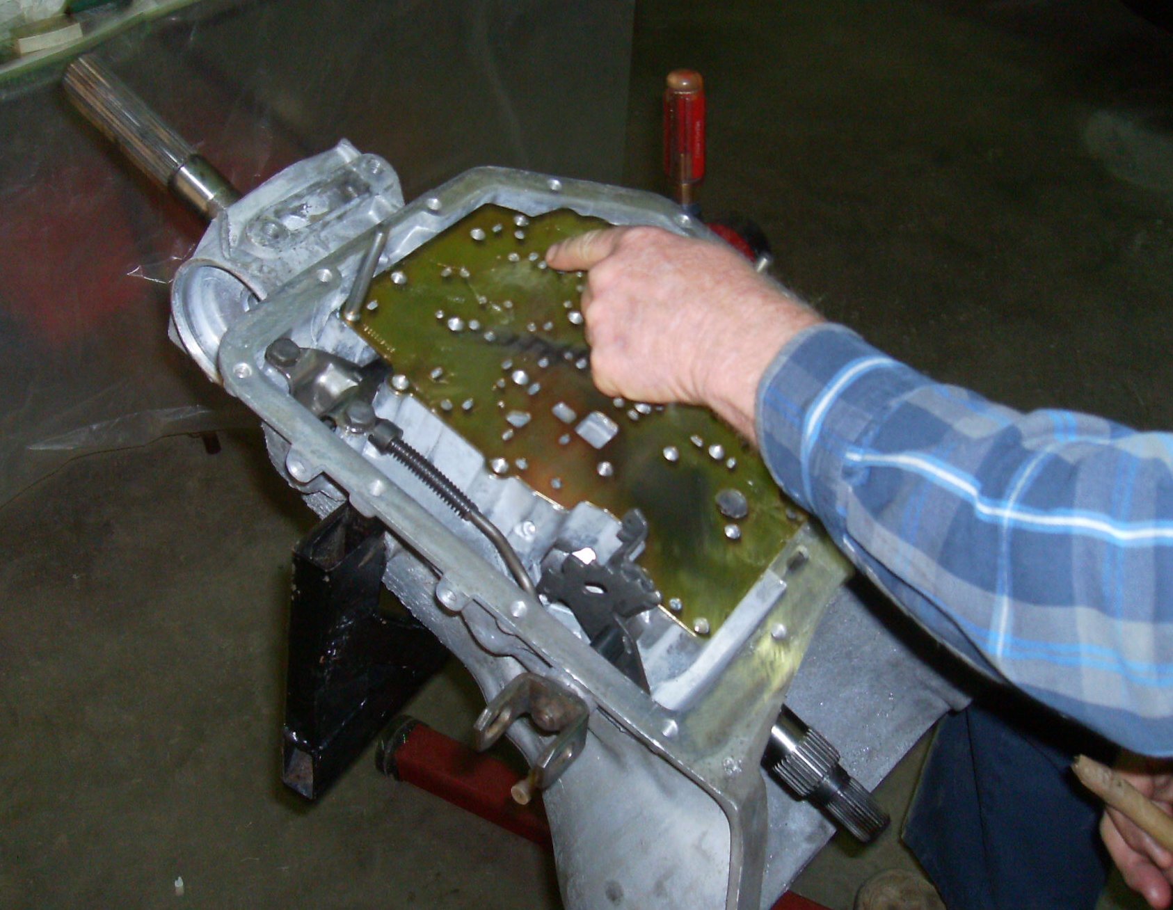
Unbolt support plate next. Tommy broke the bolts loose with the ratchet
first. You can see "silt" from the frictions where some of the valve body
passages dead-ended. It's perfectly normal, with no chunks or sparklies.

This is part of a shift kit, so it has one thick plate and two thin plates.
The two thin plates are different; make a note of the stacking order.

In this case the bottom plate has a long slot. It's for the "double oiler"
mod for the direct clutch pack.

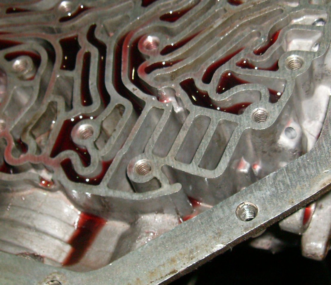
Peel the gasket up carefully. Look for spots where the it might not have made
good contact; this will tell you if the case or valve body are warped, or the
valve body bolts were incorrectly tightened. SAVE THE GASKETS, even if
they tear or break up. You will need to compare them to the new ones if the
transmission has ever had a shift kit.
Still looking pretty good.

Due to the shift kit, this transmission has only one check ball.
We used a punch and made a few marks around the position of the check ball.
You don't have to do this; if you do, just barely mark the case, don't get
crazy with it. I like the punch marks because they won't wash off like felt
tip marks might.

Use a pick or small screwdriver to remove the screen in the oil feed passage.
Early transmissions had these, later ones didn't. They don't always come with
a rebuild kit. For a racing transmission it's a good idea to have the screen.

Now lift the 2-3 servo out. Make a note of which side of the servo is up, and
the relation of the spring and spring retainer.
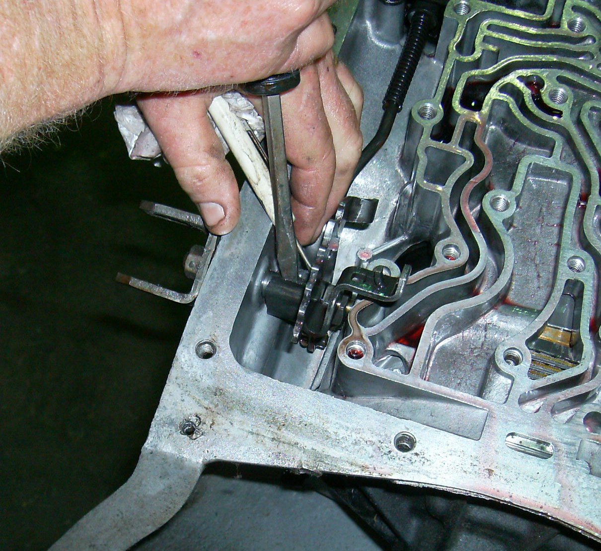
The spring clip on the selector comes off next. It likes to turn around on
the shaft while you're trying to drive it off. Don't scar the shaft
underneath.

Remove the nut from the shaft. Ours was torqued to about eleventy thousand
foot-pounds.
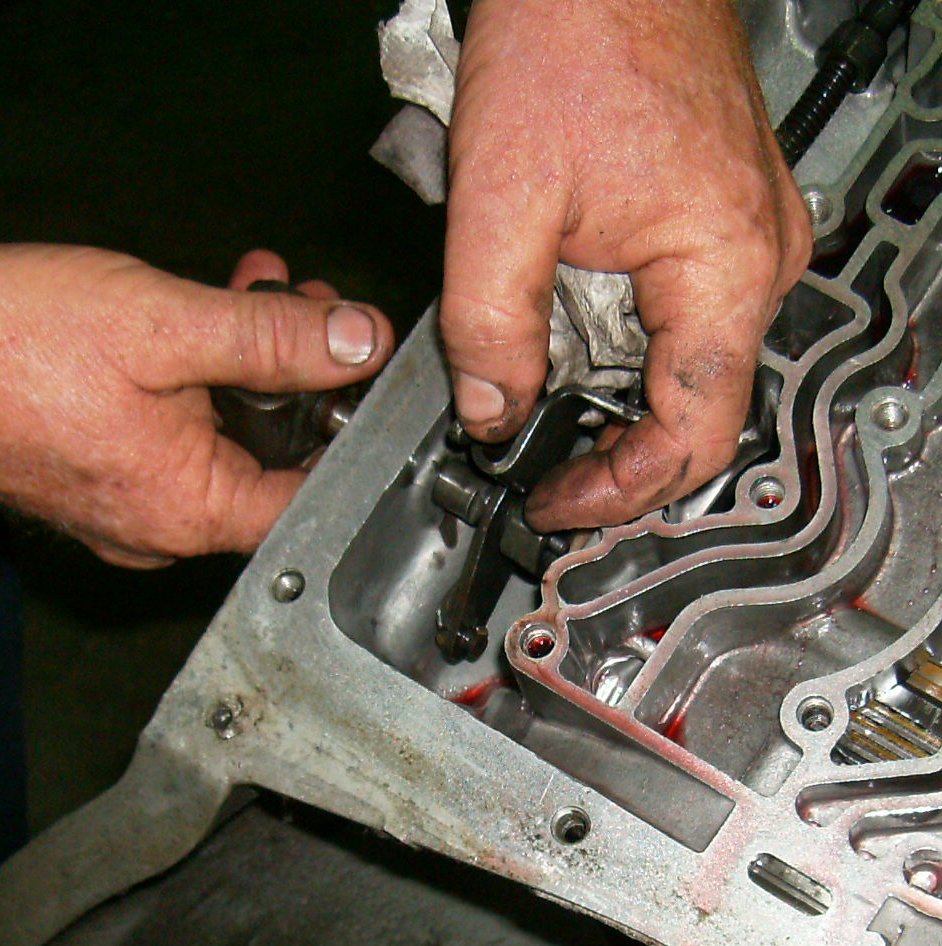
You have to work the nut and the stamped steel rooster comb off together.

Now you can get the rooster comb off.
Lift the parking linkage out of the case.
The selector shaft had a burr on the end. Use a file as necessary until it
will slide out. Don't yank and twist it out; you might scar the reamed hole
in the aluminum case. If you do you may wind up with an oil leak later.
Unbolt the parking pawl bracket from the case.

The pawl has a tension spring. You can leave the pawl, spring, and pivot
shaft in the case if you want; we removed them.
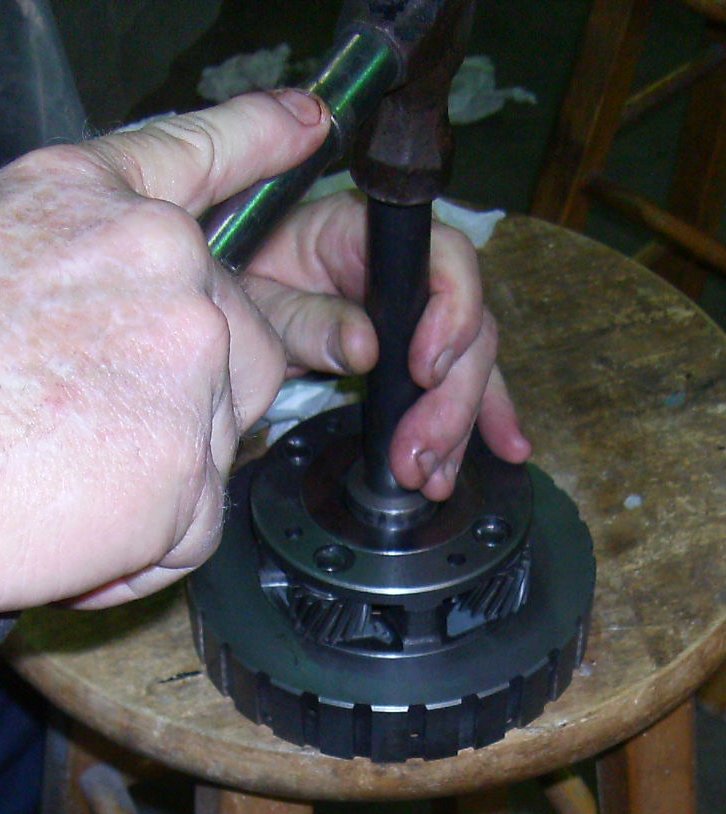
Now we're finally getting into the guts of the transmission! First step is to
screw some pieces of 3/8-16 coarse thread rod into these two pump holes, which
have matching threads to accept the rods.
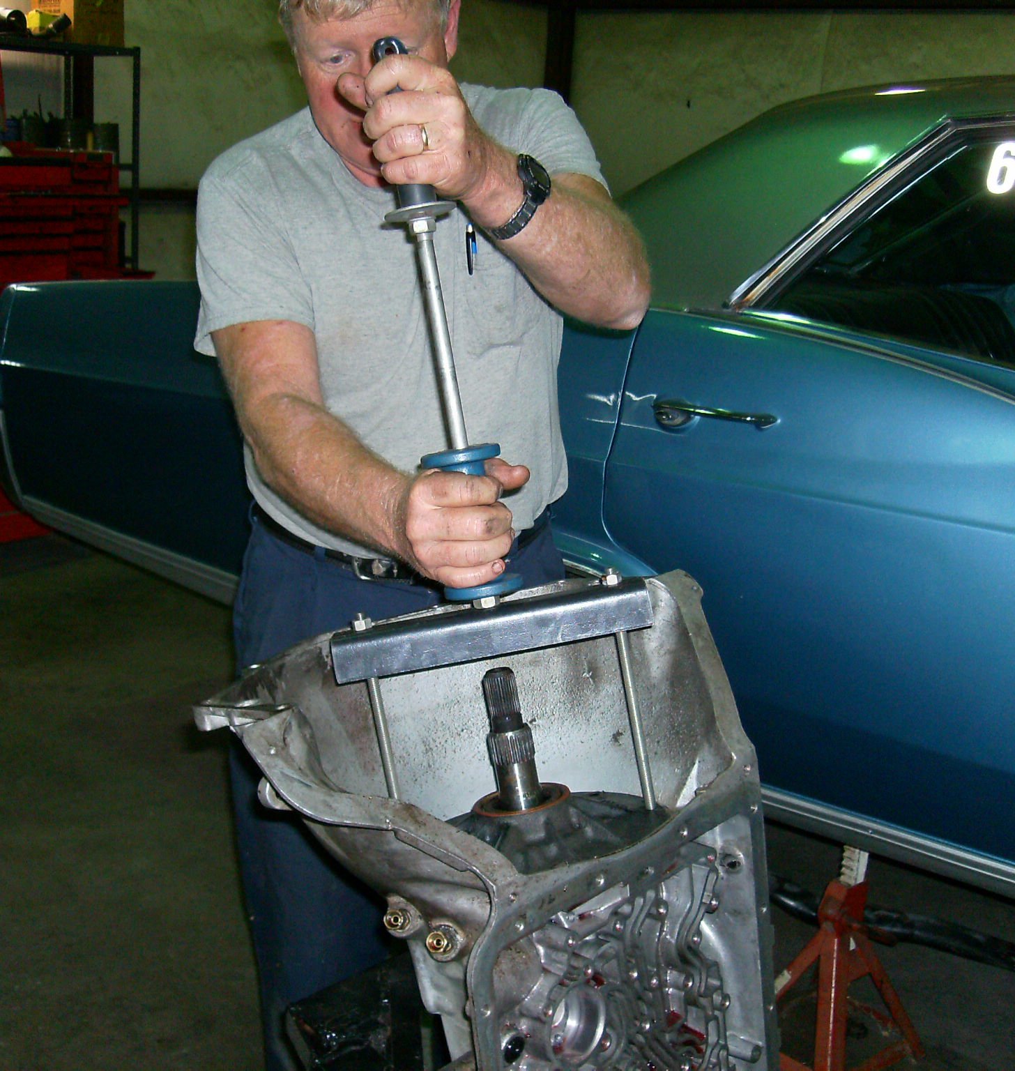
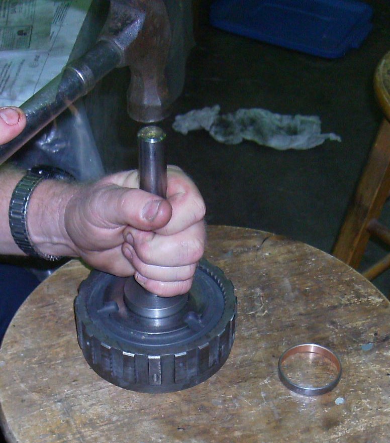
Crossbar connects slide hammer to both threaded rods. The book suggests using
two small slide hammers and walking the pump out, but a couple of bangs with
the big hammer just pops it right out.

Pump out, sitting on front of case.

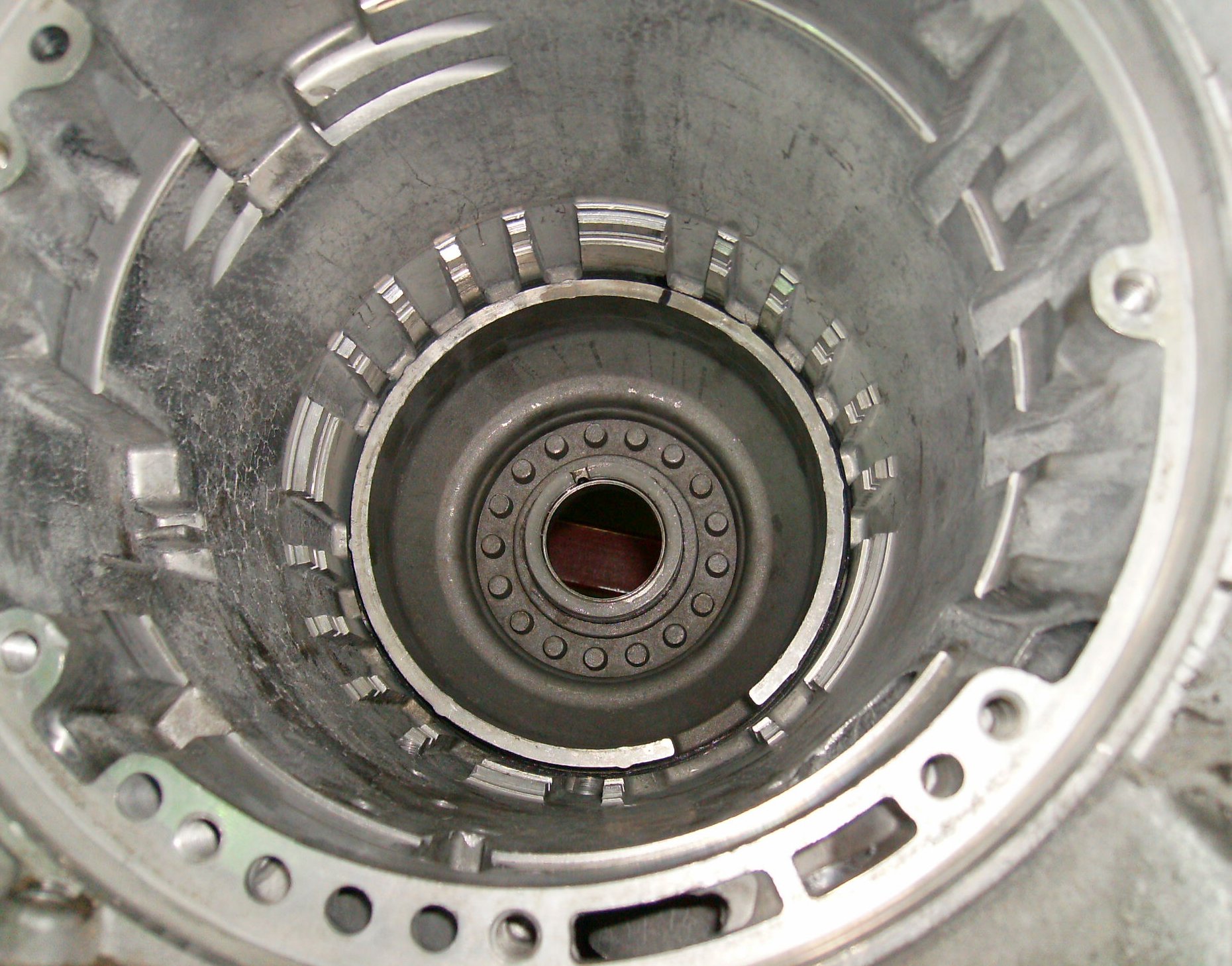
Here's the intermediate clutch pack. Lift the frictions and steels out with
bent paper clips, coat hangers, whatever is handy. You don't need to worry
about keeping them in order.
You can pull the band out now. It's springy and has lugs that fit into
sockets in the sides of the case. Sometimes you have to use one or two
screwdrivers to close it up and pull it out; other times, your fingers will
do.
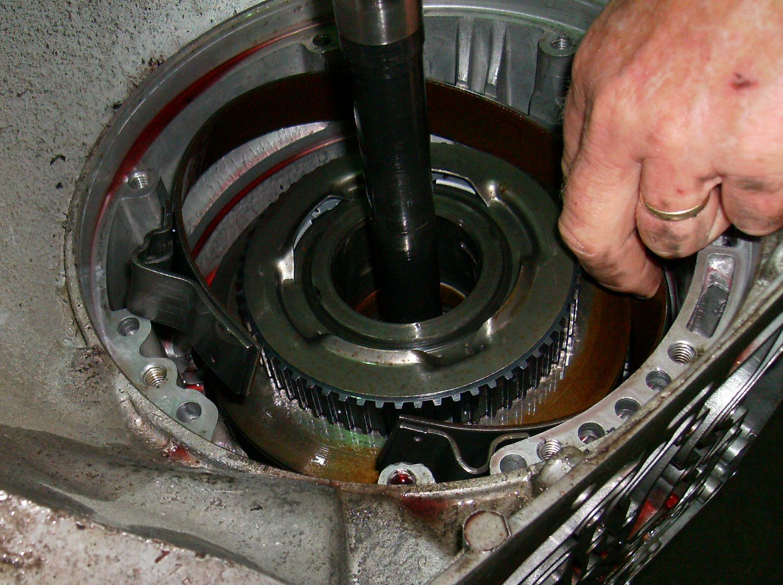
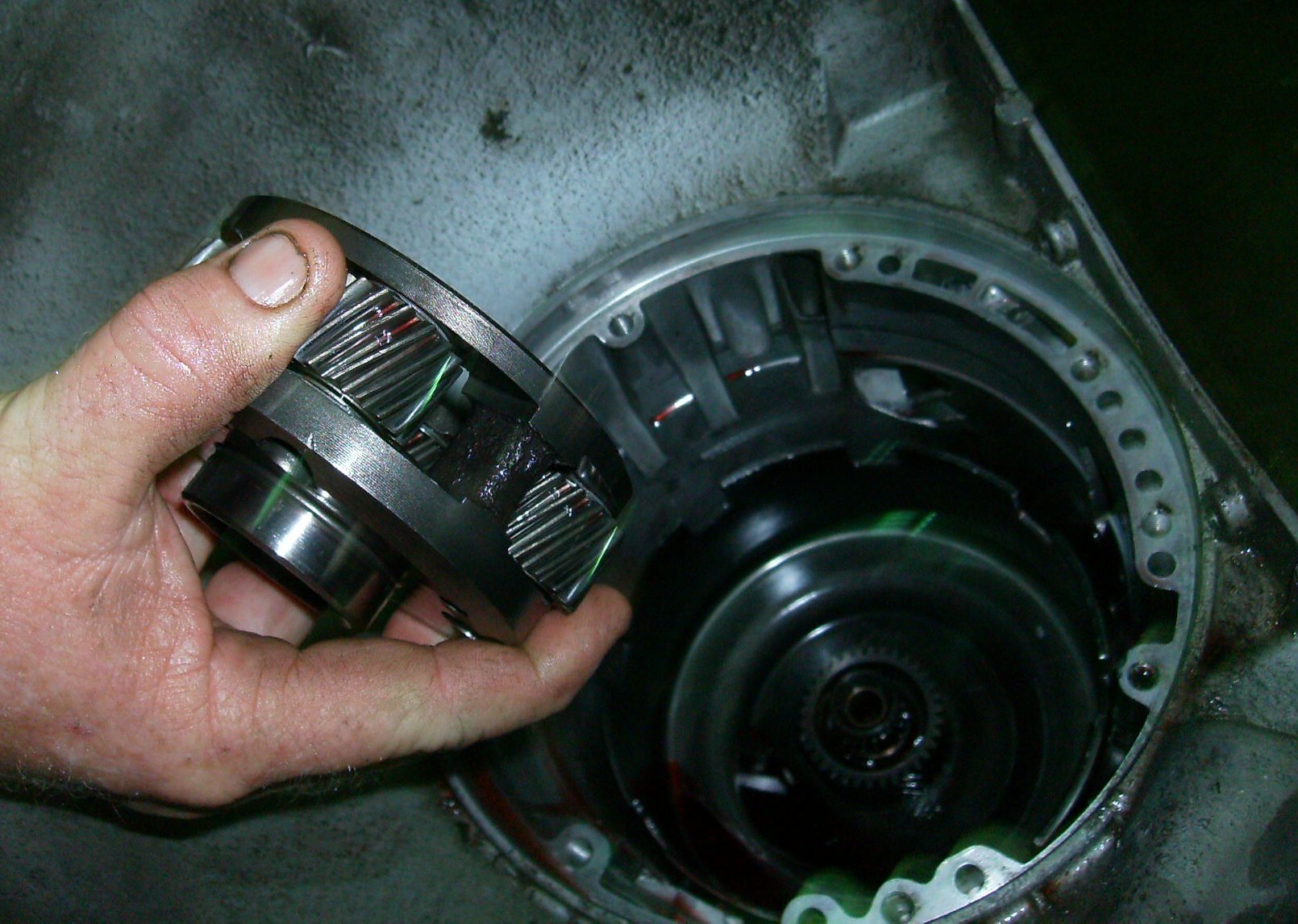
Grab the input shaft with both hands and lift the forward and direct clutch
packs straight out. Together they're noticeably heavy, so make sure you have
a good grip. Set the packs aside.
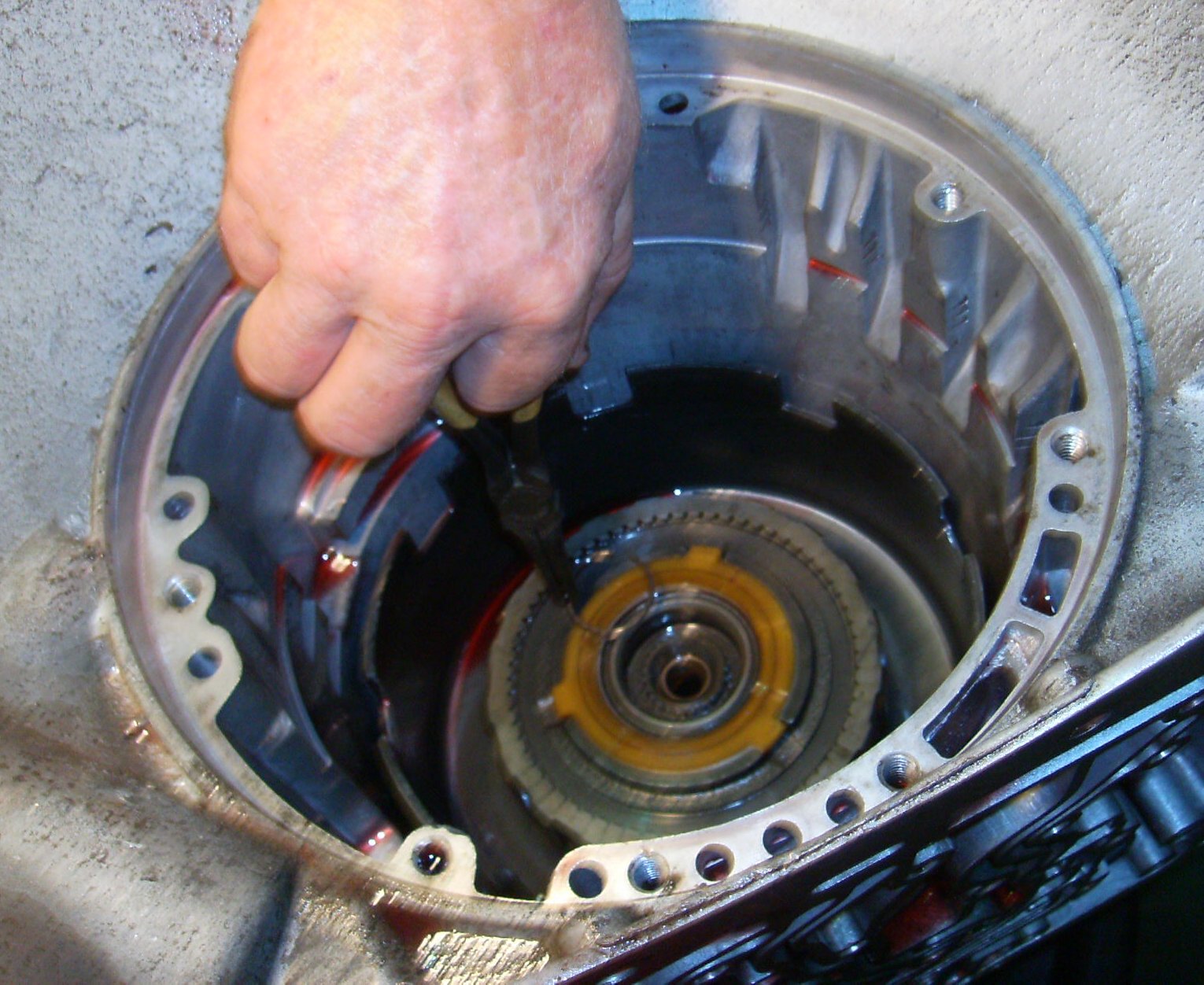
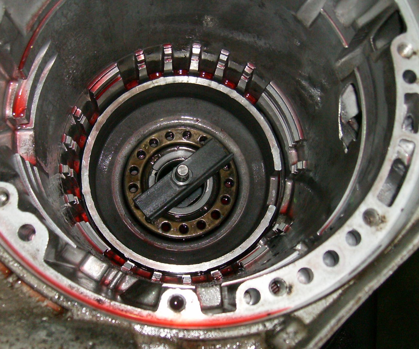
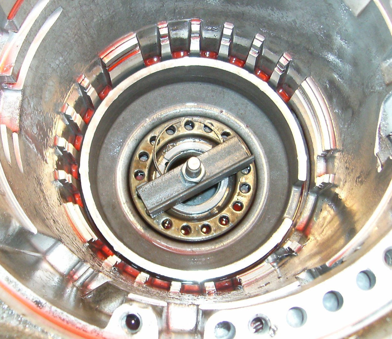
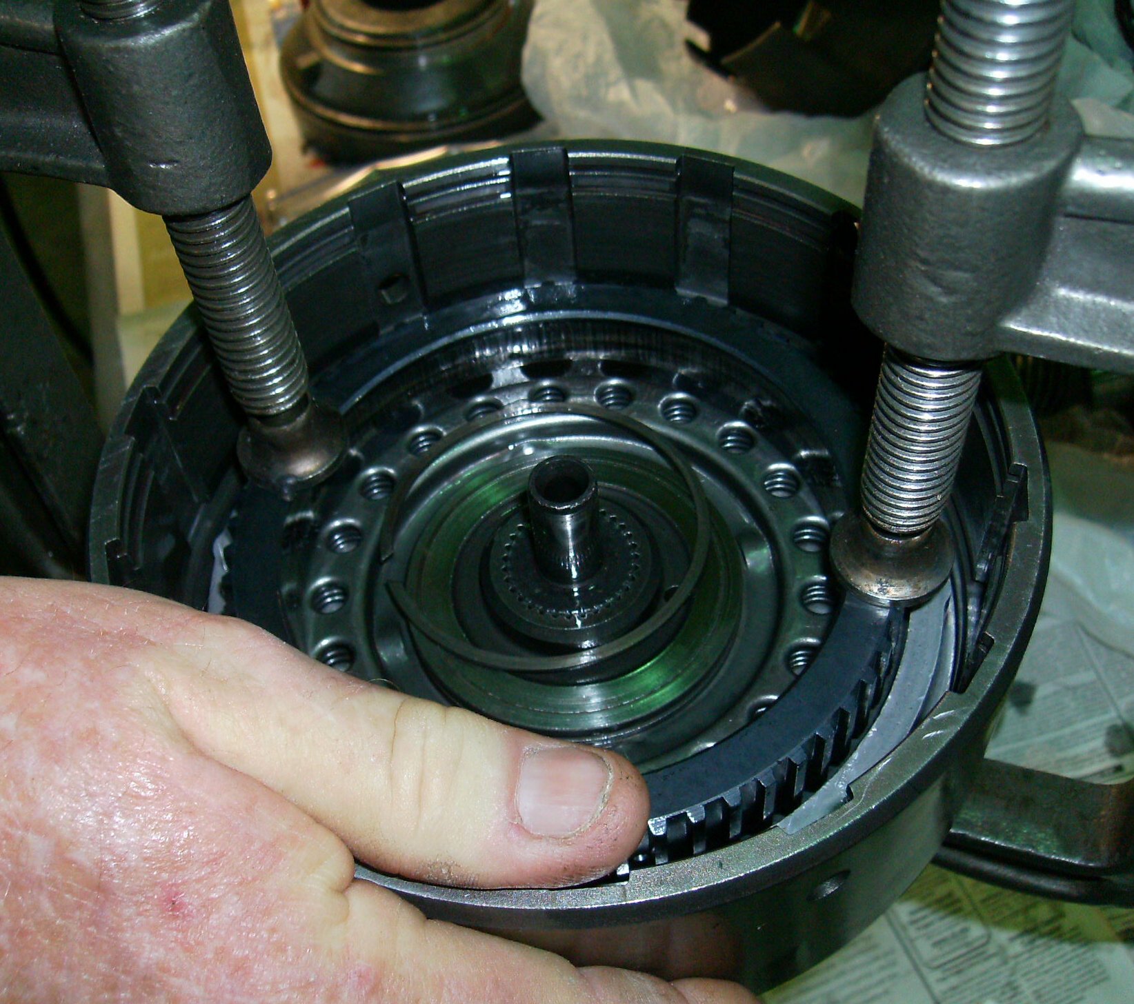
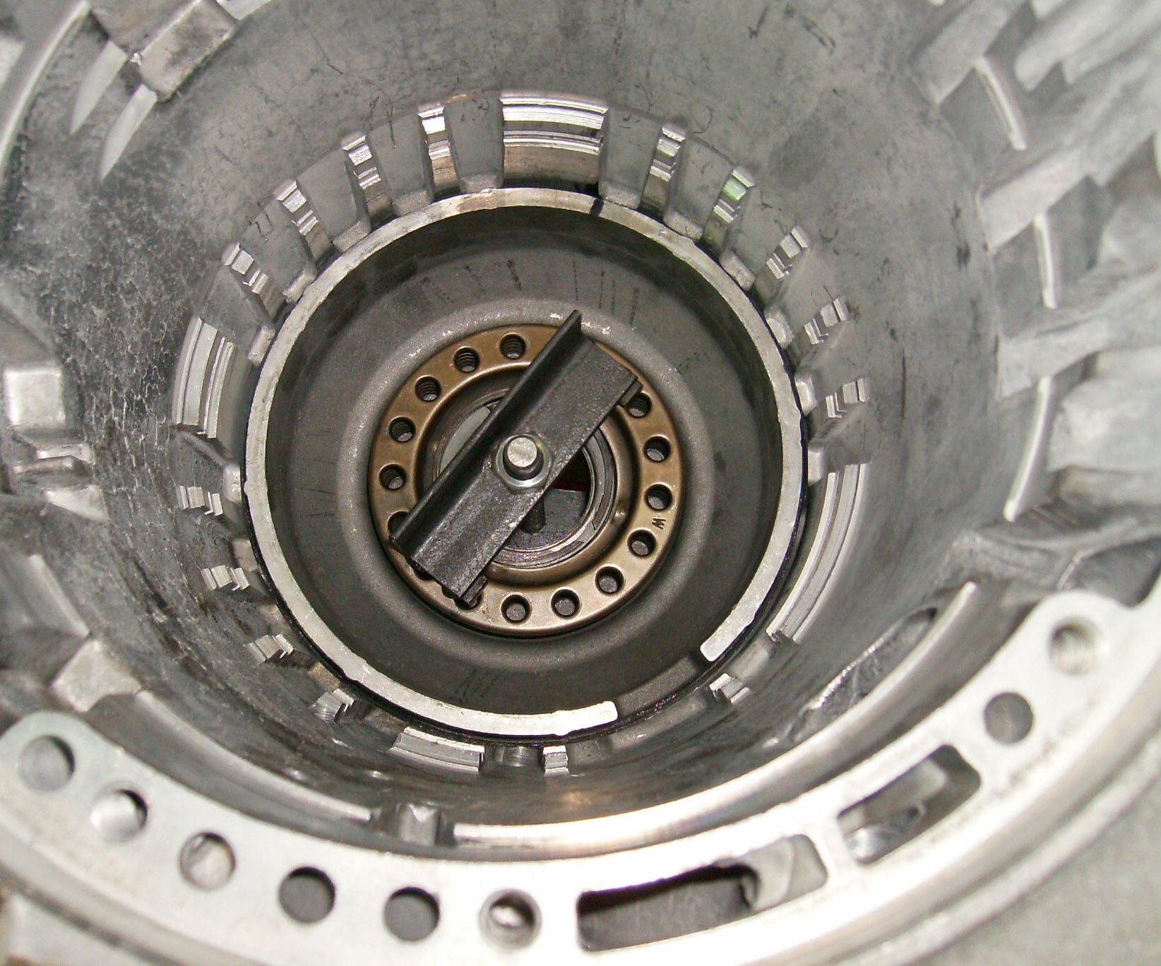
This small snap ring holds the input ring gear (the ring gear teeth are on the
inside) to the output shaft. It is not quite flush with the splines on the
shaft, and the opening is often cut at an angle that makes it hard to get hold
of. Standard snap-ring pliers can't get into the limited area to get at the
ring. You have to either grind the ends of your expensive pliers down enough
to get at the ring, or work at it with two small screwdrivers. A couple of
dental picks will also work. When using screwdrivers or picks, you can either
get your arms in there or you can see the ring, but not both at the same time.
Sometimes the ring will come right off, sometimes it's just a long,
frustrating, and profane hassle.
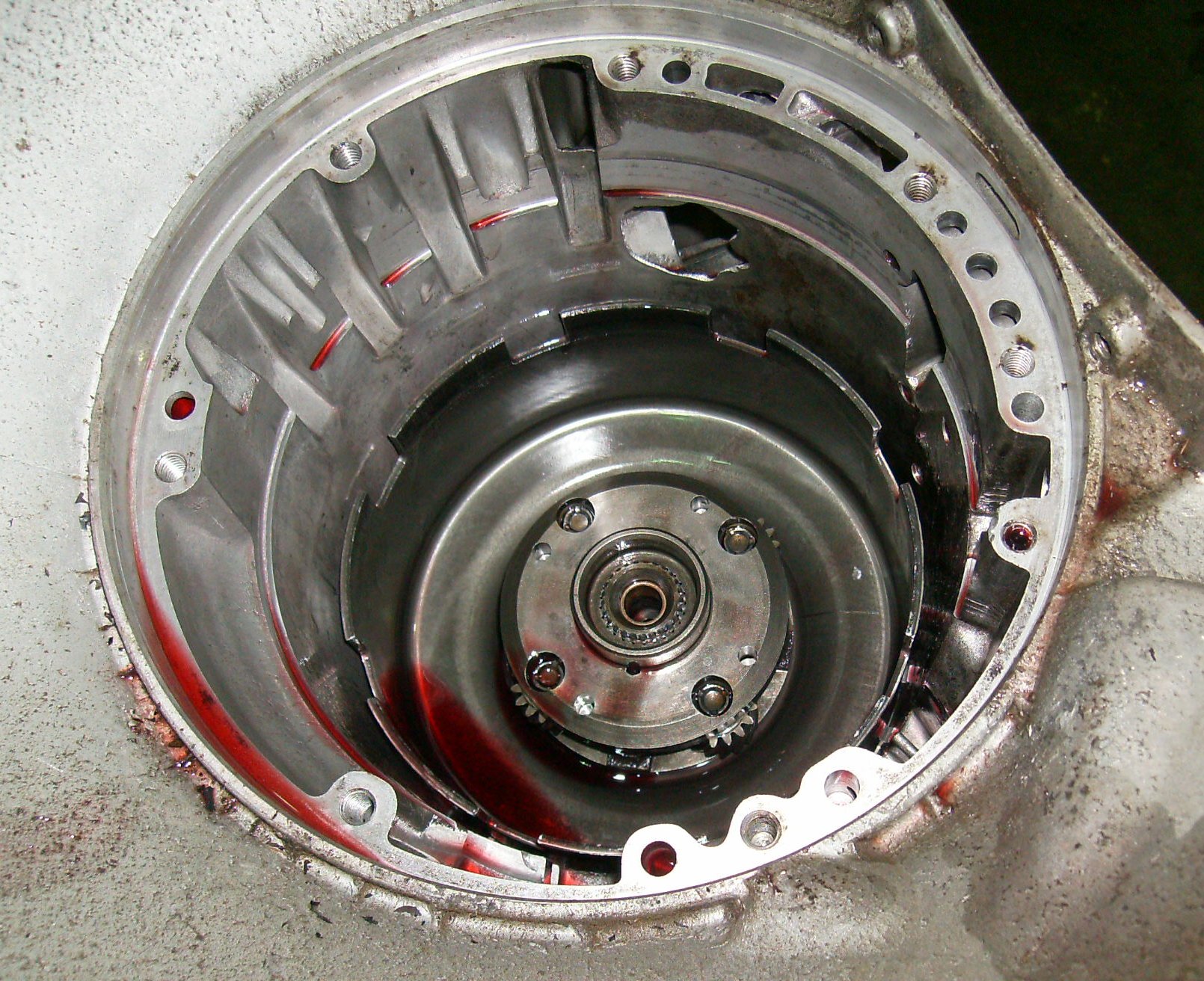
Lift the input ring gear up and off the output carrier. The planetary gears
and housing are the output carrier. Sometimes it's easy to get confused about
the names of the parts; once they are cleaned, you can write their names on
them with a Magic Marker so you don't have to refer to the book when you make
your web page...
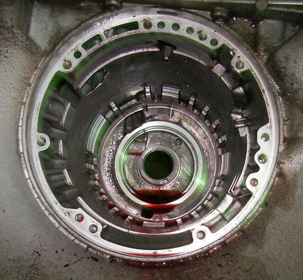
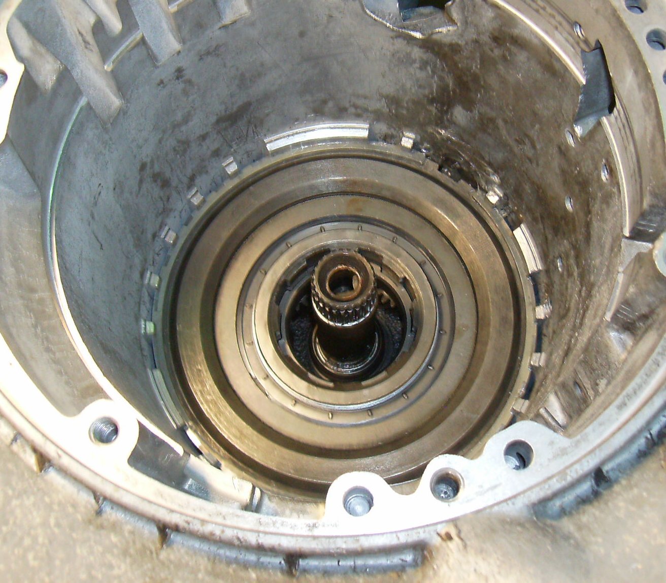
Lift the output planetary off the output shaft.
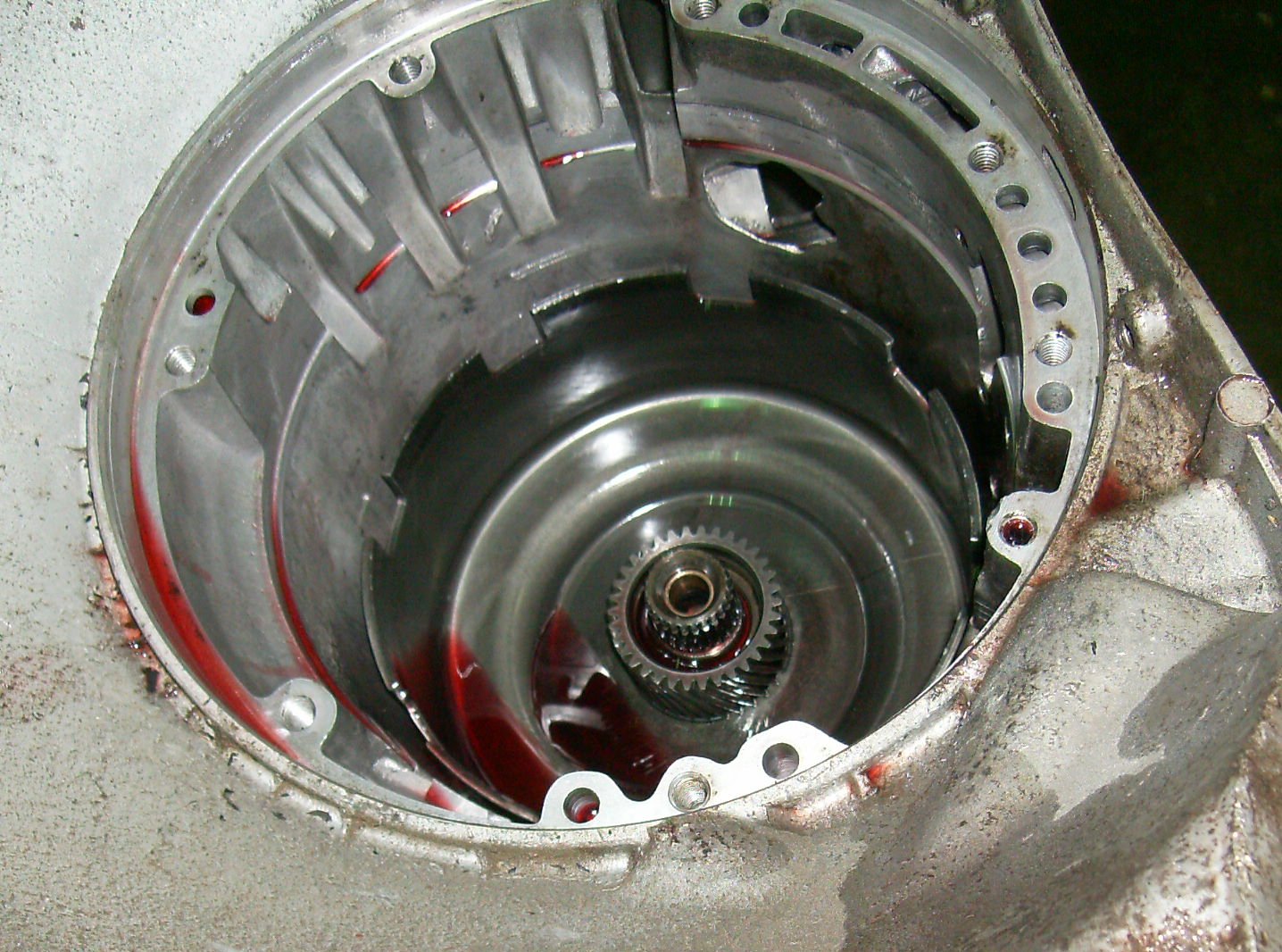
The big sheet metal half-coffee-can is the sun shell. Grab the gear and pull.
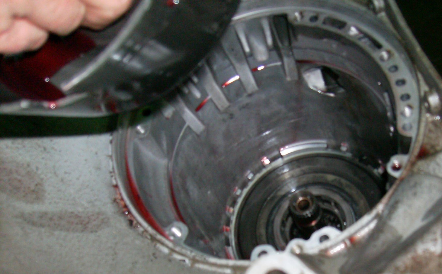
The sun shell will lift right out.

You're now at the low/reverse clutch pressure plate.
The snap ring is large and springy. A single wide-bladed flathead screwdriver
will do to lever it up, then you can take it out with your fingers.
Now you have to remove the pressure plate. The anti-rattle spring keeps it
twisted against the lugs in the case, so friction locks it in place, plus
there's no good way to grab onto it. A couple of pieces of bent coat hanger
or welding rod will help.
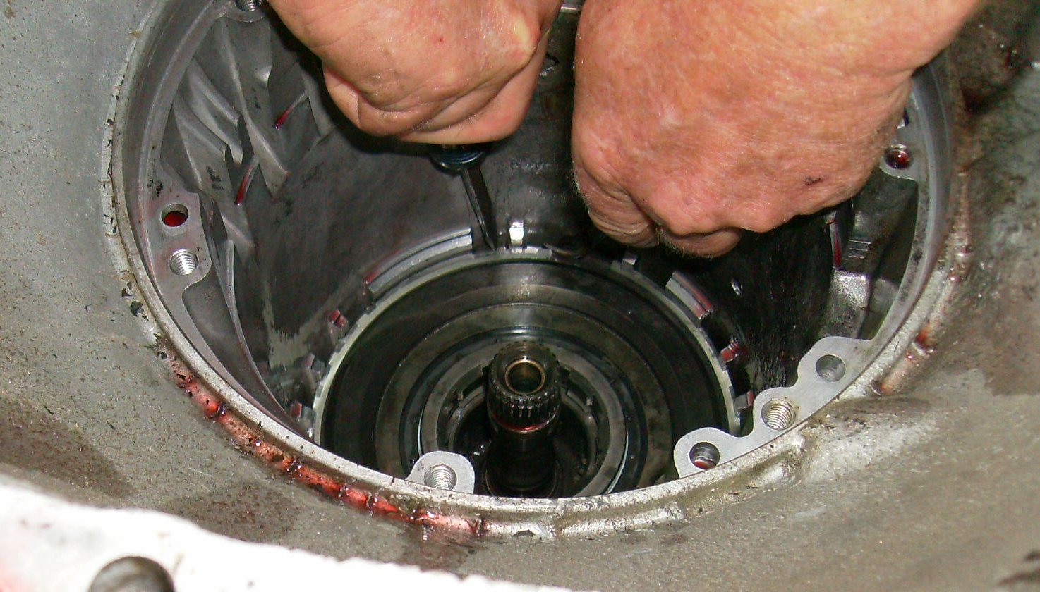
Homemade spring compressor compresses low-reverse spring.
Reach in with the snap ring pliers and remove the spring. It's way down
there, but it's not hard to remove... though you might have to grind on your
snap ring pliers a bit to get a good grip.
Grab the low-reverse servo piston and pull it out. Sometimes you'll need
needle nose pliers to work it up to where you can grab it. Then you're
looking at this - an empty case!
All the parts are out, but we're not done yet! The forward and direct clutch
packs and the front pump need to come apart next.
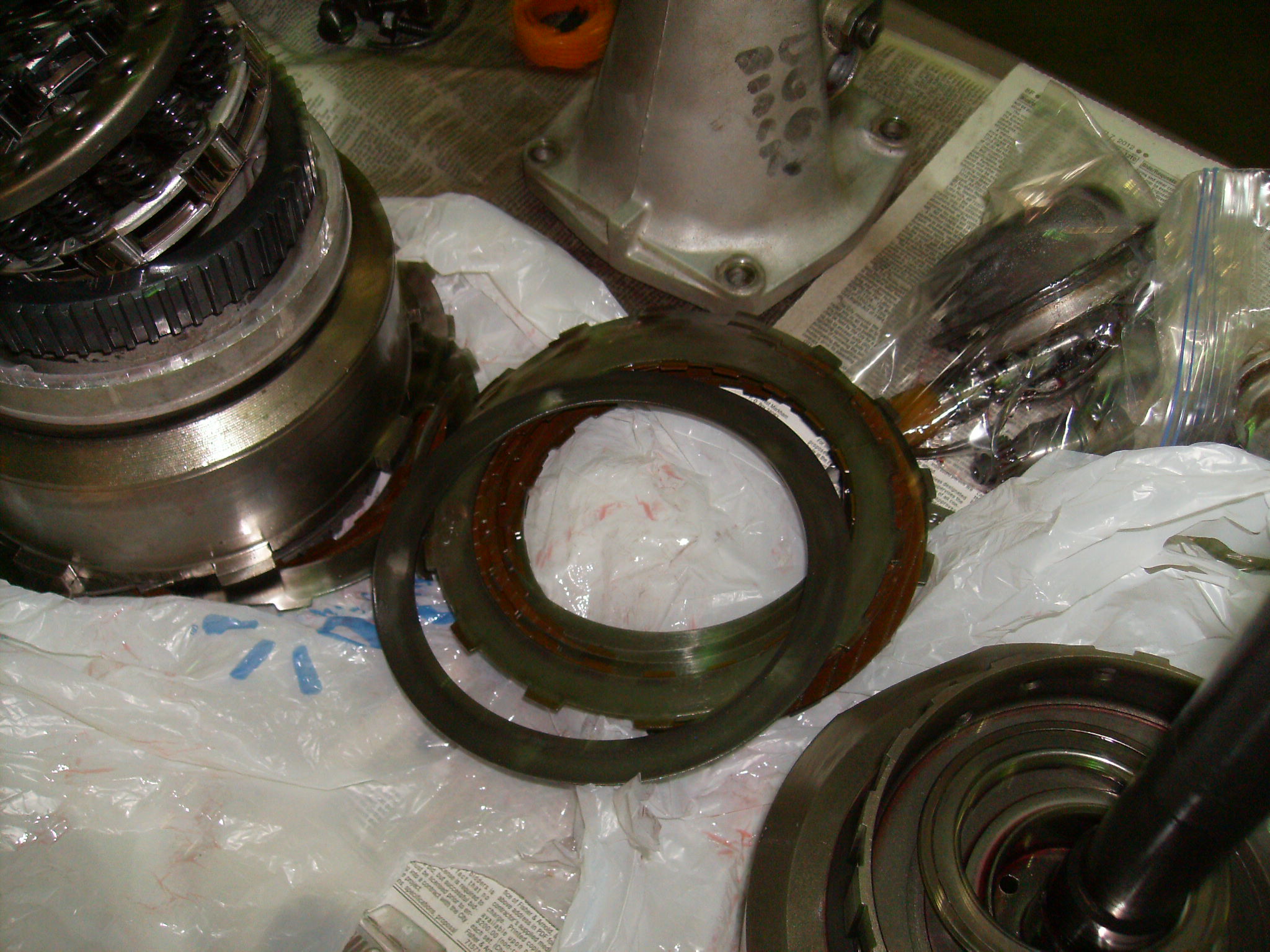
Lift the direct clutch pack off the forward clutch assembly.

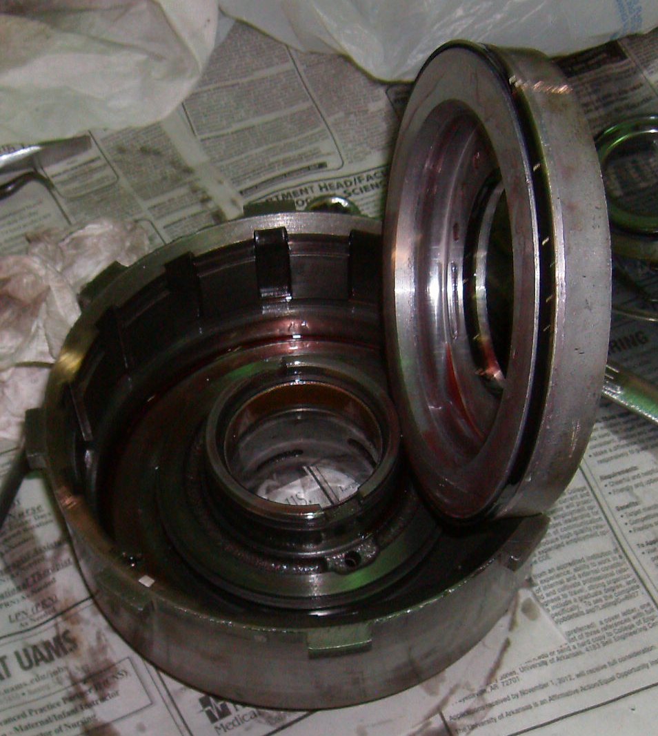
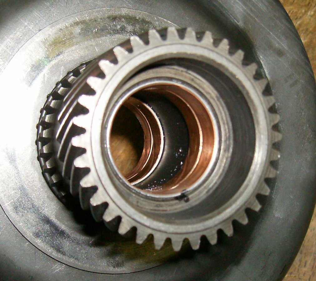
On the front of the forward clutch pack is the one-way sprag clutch, called
the "intermediate clutch overrun outer race." A stock ring is silvery or
shiny; the dark color says this is an aftermarket hardened ring. It was
installed by the previous builder. The ring is a known failure point of the
T-350, so it is recommended a hardened sprag ring be installed for a high
performance build.

605 passes with a stout engine and a two-ton Impala have brinnelled the inside
of the ring. It's quite rough to the touch. A replacement is $45.
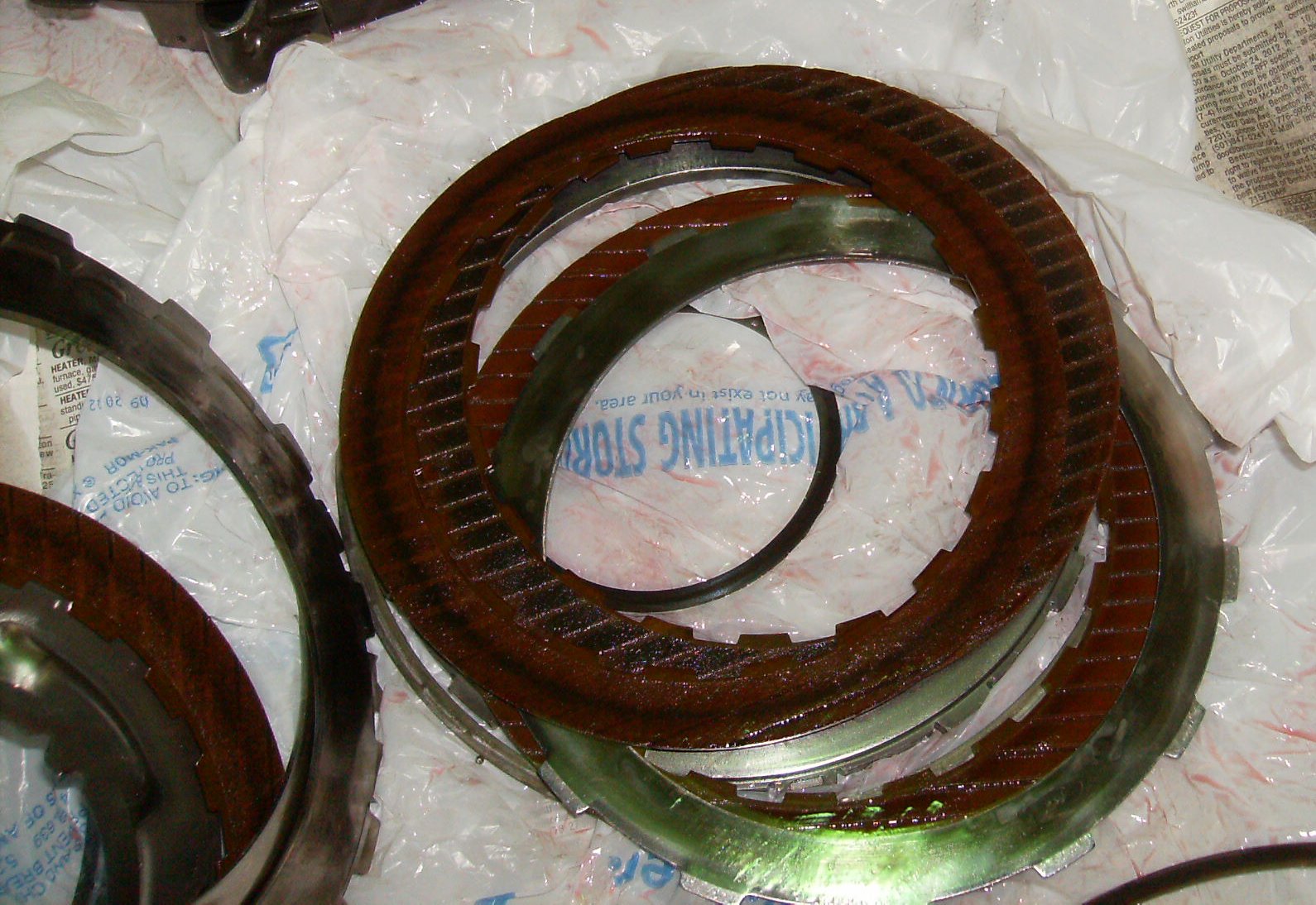
The direct clutch (the first one) clutch had been failing, causing the soggy
shifts. It isn't dead yet, but it's close. The steels are blued and blotchy.

The frictions don't look do hot either.

Another snuff shot.

The ramps on the direct clutch drum were, amazingly enough, okay.

There's a slight amount of wear, but no divots. This is a Buick-built drum
and technically the ring is removable - you can see the fine splines just
below the snap ring groove - but the ring isn't a service part any more.

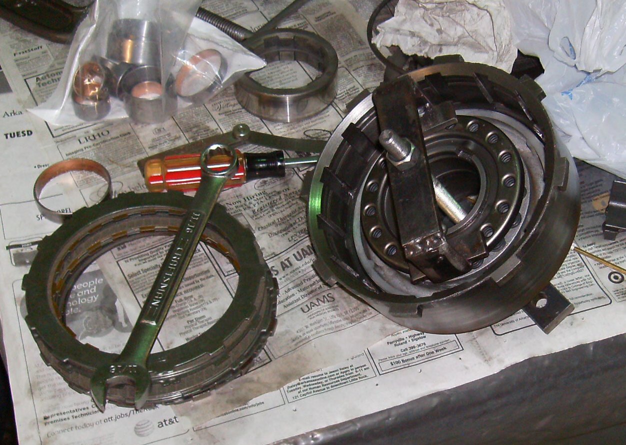
Another homemade spring compressor on the direct clutch drum. The snap ring,
pressure plate, frictions, and steels have already been removed.
Once the spring plate is out you can remove the piston.
Parts!
The forward clutch drum is a bit harder to get apart. Use a couple of large
C-clamps and the sprag race to compress the spring pack,
Parts!

Will it ever go back together?
Never in a million years...

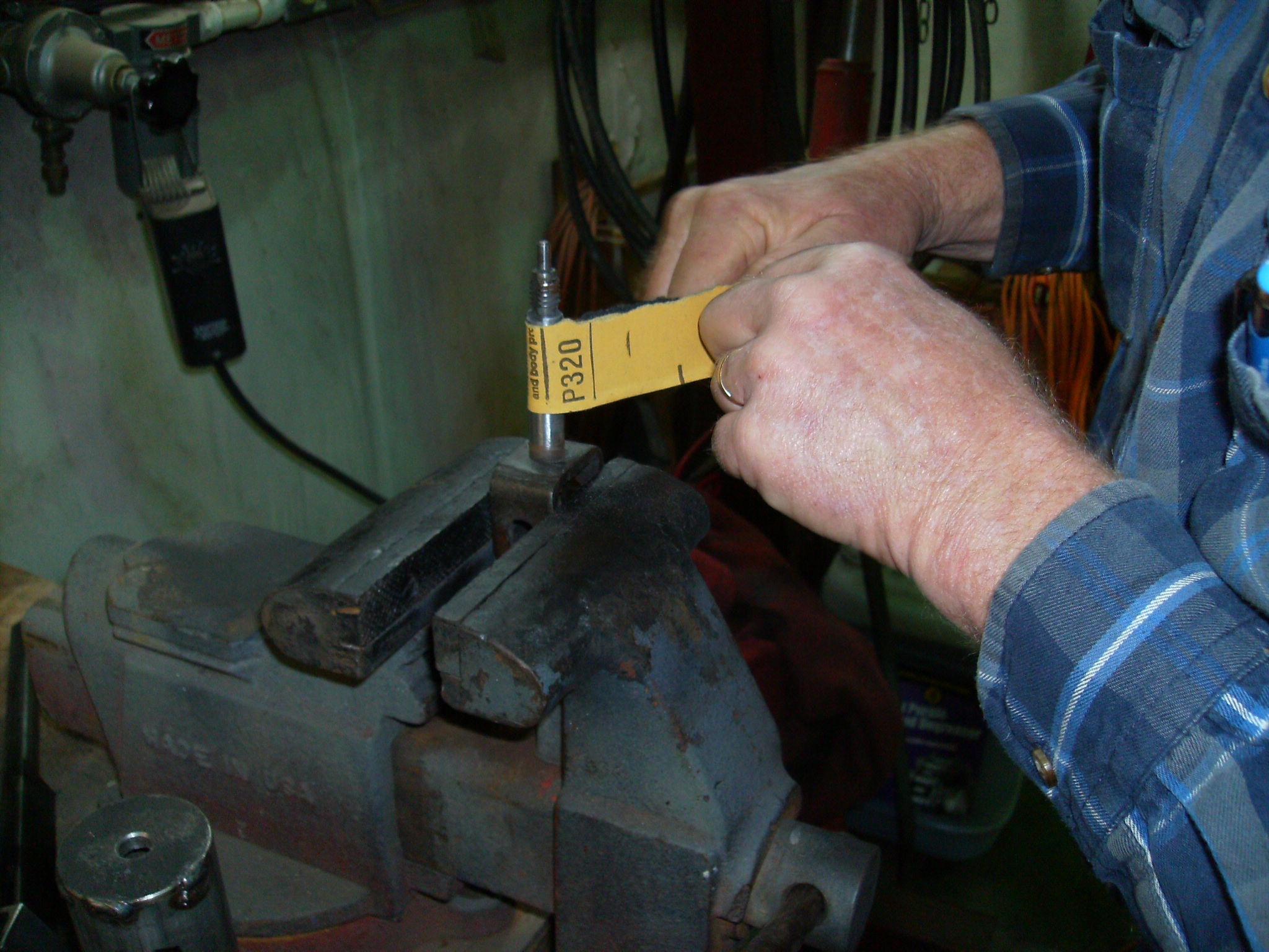
I'd always used feeler gauges to work the seals down when reinstalling the
pistons, but this time I made the tool recommended in the book. .023 MIG wire
and some 1/8" brass tubing worked fine. I tried soldering the wire into the
tube, but while modern lead-free solder works fine for copper pipes, it's not
much good for soldering other stuff. I crimped it with vise grips and it
worked well enough.
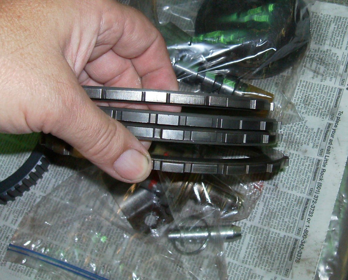
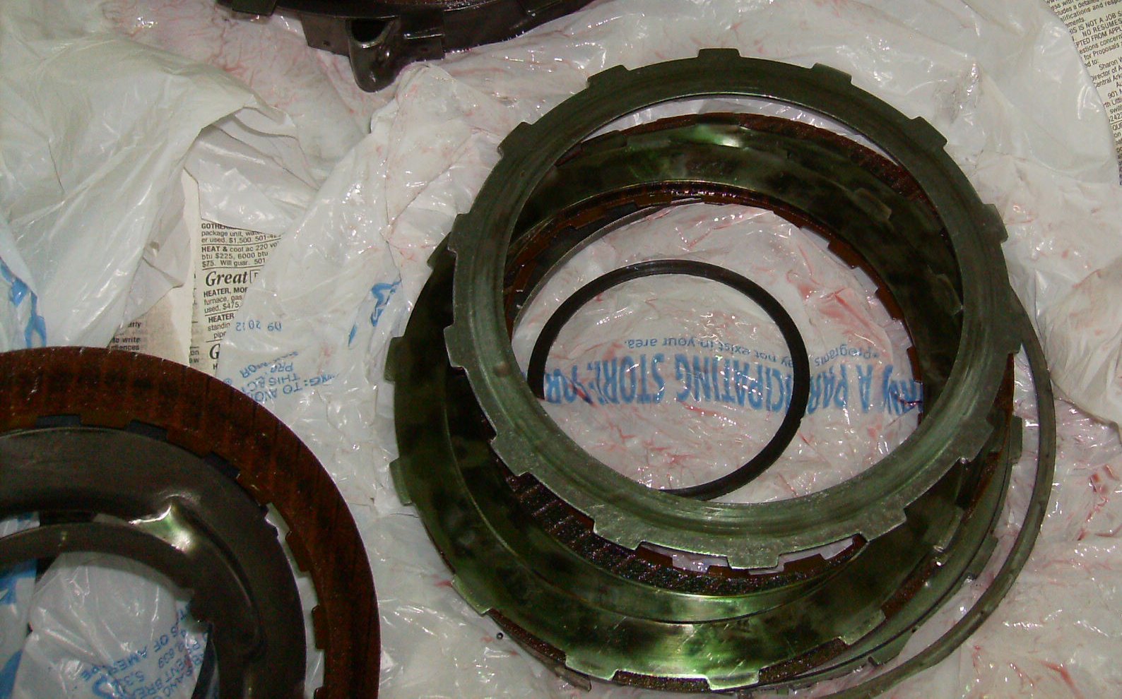
Spare pressure plates from the parts box. GM has three different
thicknesses. Here are two thin ones on top, a thick, and
After replacing the seal rings, lube the piston and reinstall. Use the wire
tool to work the seals down. Be very careful not to snag a ring or let it get
flipped over.
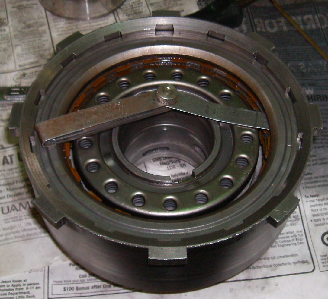
Use the spring compressor and reinstall the spring pack.
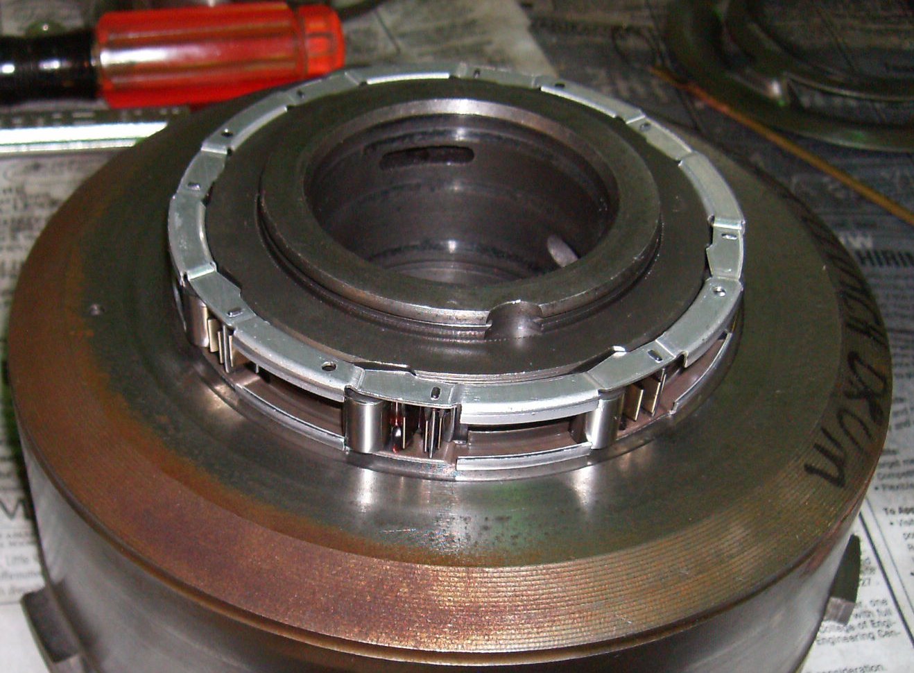
The sprag clutch goes back on the front of the direct drum. You can jam it on
backward, but if you look you'll see the inside is shaped to match the ramps.
Nothing much holds the rollers in place; be careful or they will escape.


Now we do the sun shell drum. If the old bearings are in spec, drive them
just enough deeper into the shell to leave room for new bearings in front of
them. If they're worn, replace them, and get another set so you can double
them up.
Typically, the inner bearings will partially or completely block the small oil
holes in the sides of the gear. Use a 1/8" drill bit and drill through the
bearing to open the hole completely. Use a pocket knife to remove any burrs.

When we opened the front pump it was very bad; not only were the bushings
worn, it looked like sand had gone through the gears. We traded it on on a
rebuilt pump for $78. Which, though it had new bearings, didn't come with a
front seal, so we had to install one.
The felt-tip lines are to let us quickly line the pump up in the case when
reinstalling.
Now we're finally ready to start reassembly!
Replace the oil seals on the low/reverse piston, lubricate the seals, and set
the piston down in the case. There's a lug on the back of the piston that
fits into a divot in the case to keep it from turning. Sometimes you can just
push the piston into place, sometimes you need to tap carefully with a hammer
handle. Be careful not to hit the center where the snap ring goes.
Use the spring compressor and reinstall the snap ring. Usually you can just
lever the ring into place with a thin-bladed screwdriver.
Drop the output shaft into place. It should spin freely.

There's no way to directly measure the clearance of the low/reverse stack.
You have to install some kind of shims and measure those. We used the
traditional stack of coins. Fortunately the tolerance is quite wide here.
Use a big gob of Vaseline to hold the anti-rattle clip in place. The clip
only goes in one way.
Drop the pressure plate in place. You'll probably have to use screwdrivers to
lever it into position and twist it against the tension from the anti-rattle
spring.
Make sure you put the big retaining ring back in!
This is the hole you use to air-check the low-reverse piston. The book says
use 30 PSI. You'll hear the clutches "thunk" together as the piston moves
forward. Listen for hisses or odd noises that might indicate a leak. You'll
probably hear *some* hissing, though.
FURTHER ASSEMBLY
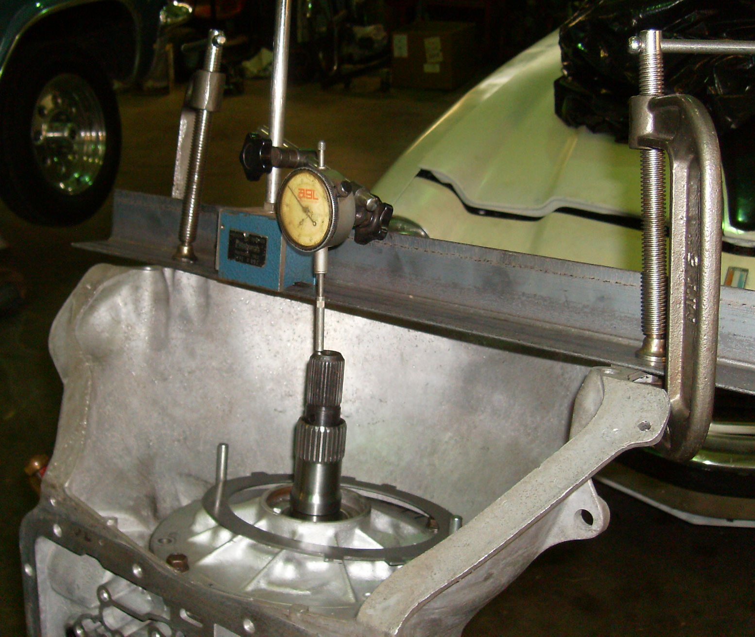
This shot shows the headless 5/16 coarse thread bolts we used to locate the
valve body and pump for installation. I'm not sure why the steel is laying on
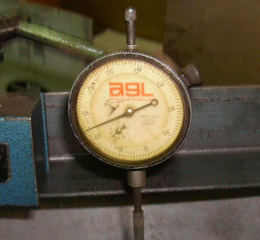
the pump. Turn the transmission facing up, set the dial indicator to zero,
and lift on the output shaft. You should see between .010" and .045"
clearance.
In this case, the shaft didn't move at all. Something wasn't right.

And we take it apart again...

...seems like deja vu all over again...

Back apart... We look for a mispositioned thrust washer lug jacking a washer
up, lipped Torrington bearing upside-down, etc. This is the third or fourth
time, and we've replaced all the new thrust washers with the very worn washers
we took out of it. Still zero clearance.
We swapped thrust washers and bits and probably had the transmission apart a
dozen times, all the way down to the empty case.
In the end, it turned out to be the #40 shim. Yes, the one at the very bottom
of the case; the first part that goes in, under the thrust washer. Well,
sometimes. Not all transmissions had the shim; early ones did, later ones
didn't. Apparently the previous builder had swapped some major components
with later ones while retaining the shim, which gave him a negative stack.
Theoretically catastrophic, but it worked that way for years. We removed the
unnecessary shim and put it back together again.

Finally we have some clearance! And we can probably assemble a T30 in
our sleep, having had plenty of practice.
.024", right in the middle. We have all the thickest of the new thrust
washers and removed the shim.
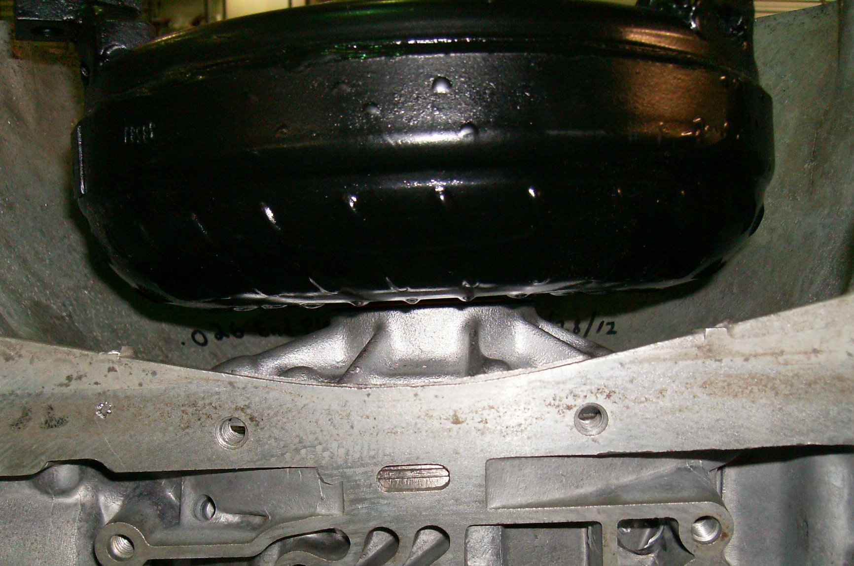
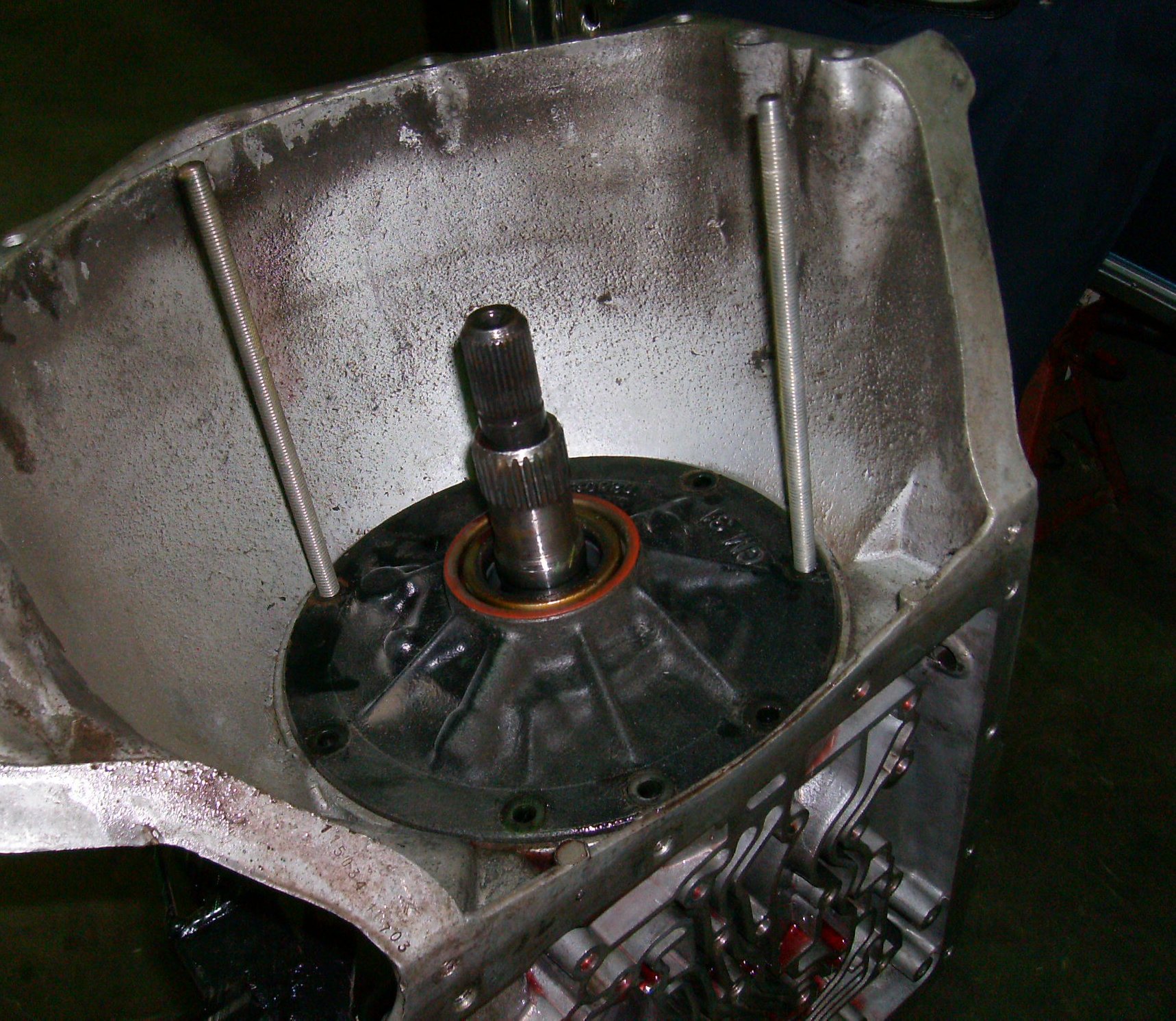
Now we make sure the new torque convertor is sitting down properly. You know
a used convertor fits, but there's always a chance a new one isn't properly
machined, has a burr, etc. It's best to find out before you're under the car.
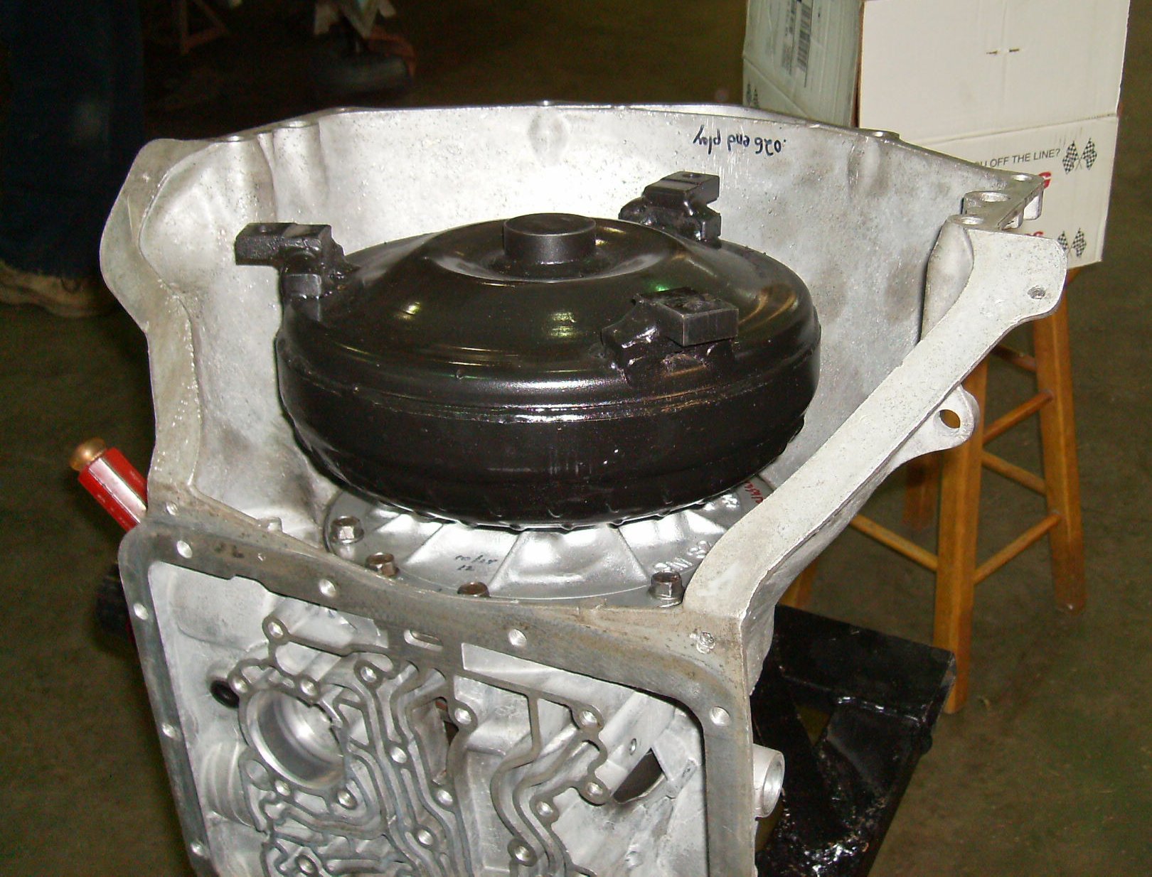
Cute little thing, isn't it?

We're supposed to have about 3/4 inch from the front of the case. Bingo.
Now we can assemble the outer bits.
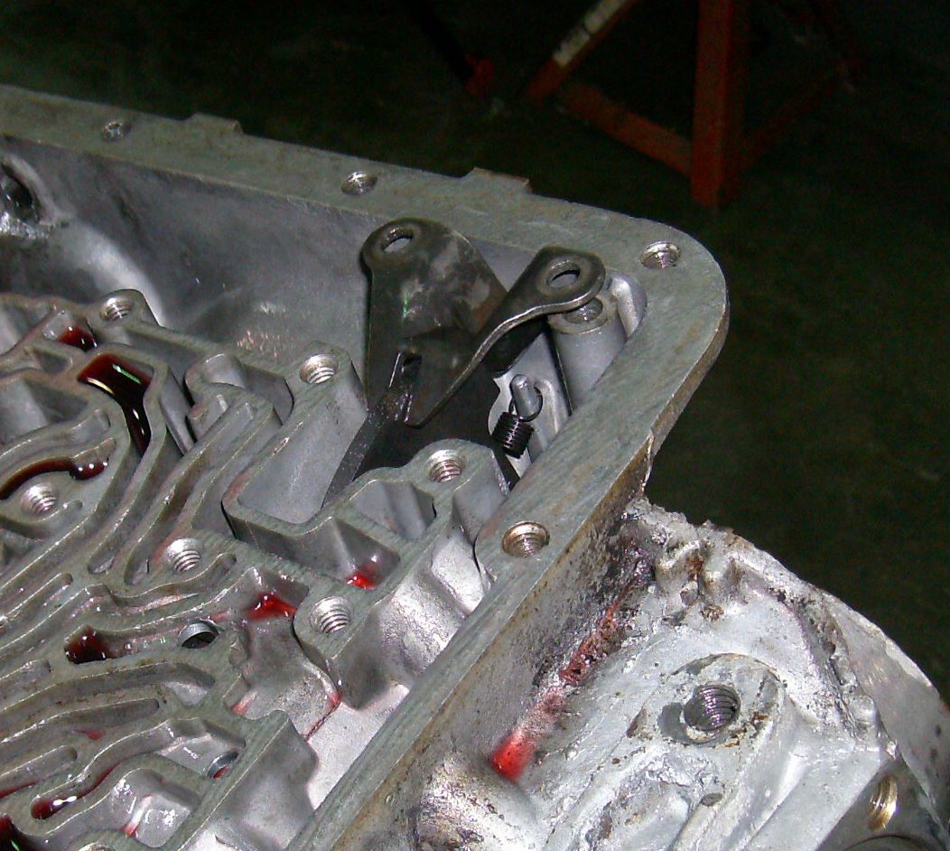
Hold the parking pawl away from the bracket while torquing it down.
The selector shaft was rough, so we polished it.
I'm not sure what Tommy is pointing at. Notice the alignment bolt on the
left.
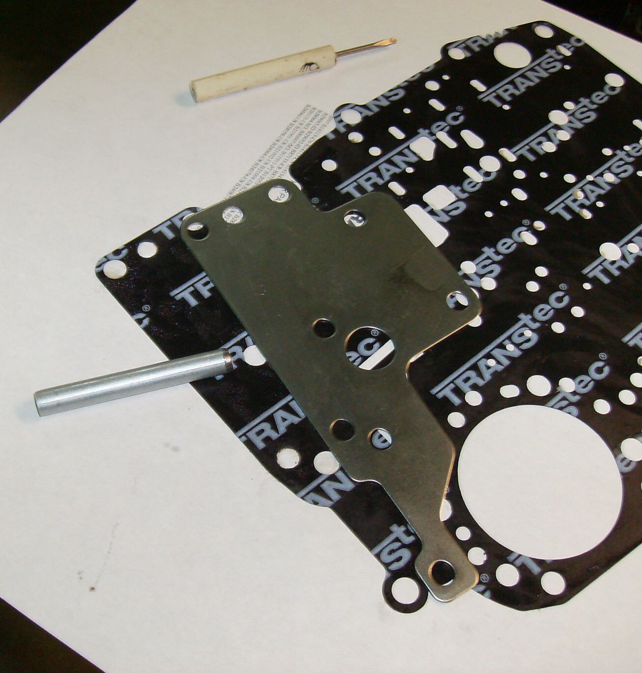
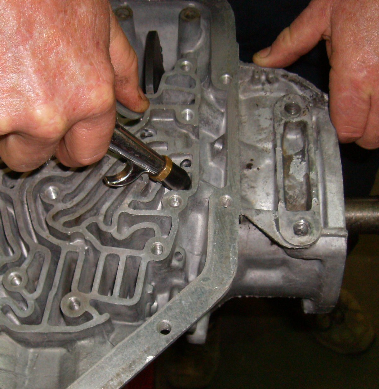
The shift kit installed by the previous builder needed two extra holes in the
lower valve body gasket. We used the spacer plate as a guide and a sharpened
piece of fuel line as a punch.
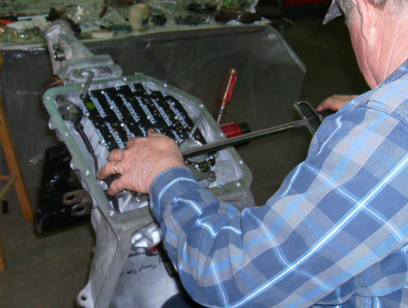
Tommy is using a torque wrench to install the spacer plate. Torque is 10-13
foot-pounts; "one-finger tight". If you have a shift kit, make sure any extra
plates are stacked in the correct order.
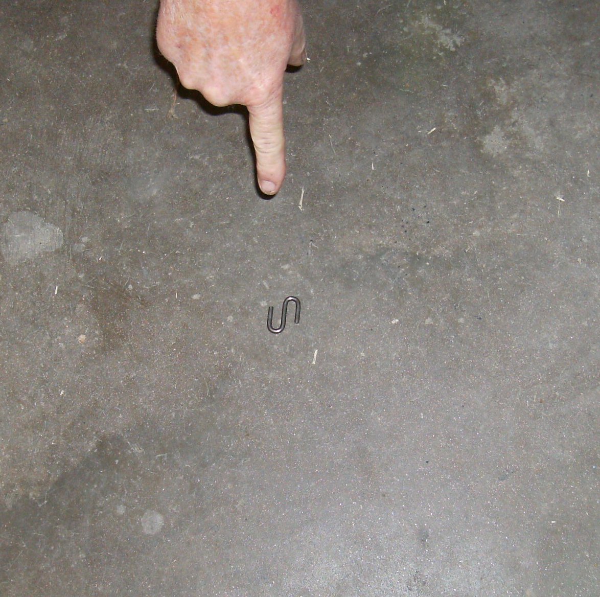
The S-clip on the manual control valve fell off when we were installing the
valve body. I'd never had that happen before. Of course, it found a nice
opening and disappeared down in the guts of the transmission. Tommy tried
fishing it out with a magnet, etc. No go. Much depression ensued. Being at
the end of a long evening of work, we put the bag over the transmission and
quit for the night.
The next evening we pulled the front pump, intermediate clutch pack, direct
and forward clutch packs, and the band for the umpty-dozenth time and flipped
the transmission face down.

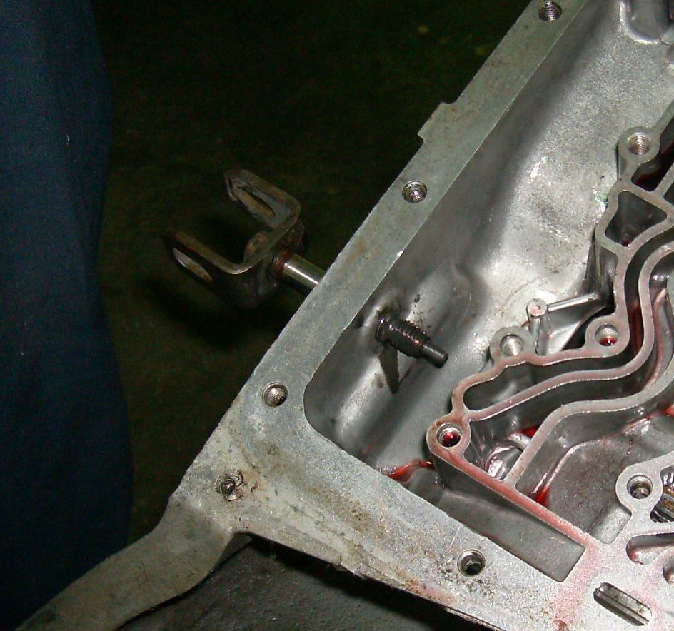
The clip fell out on the floor; that's it about a foot to the left of the
front wheel.
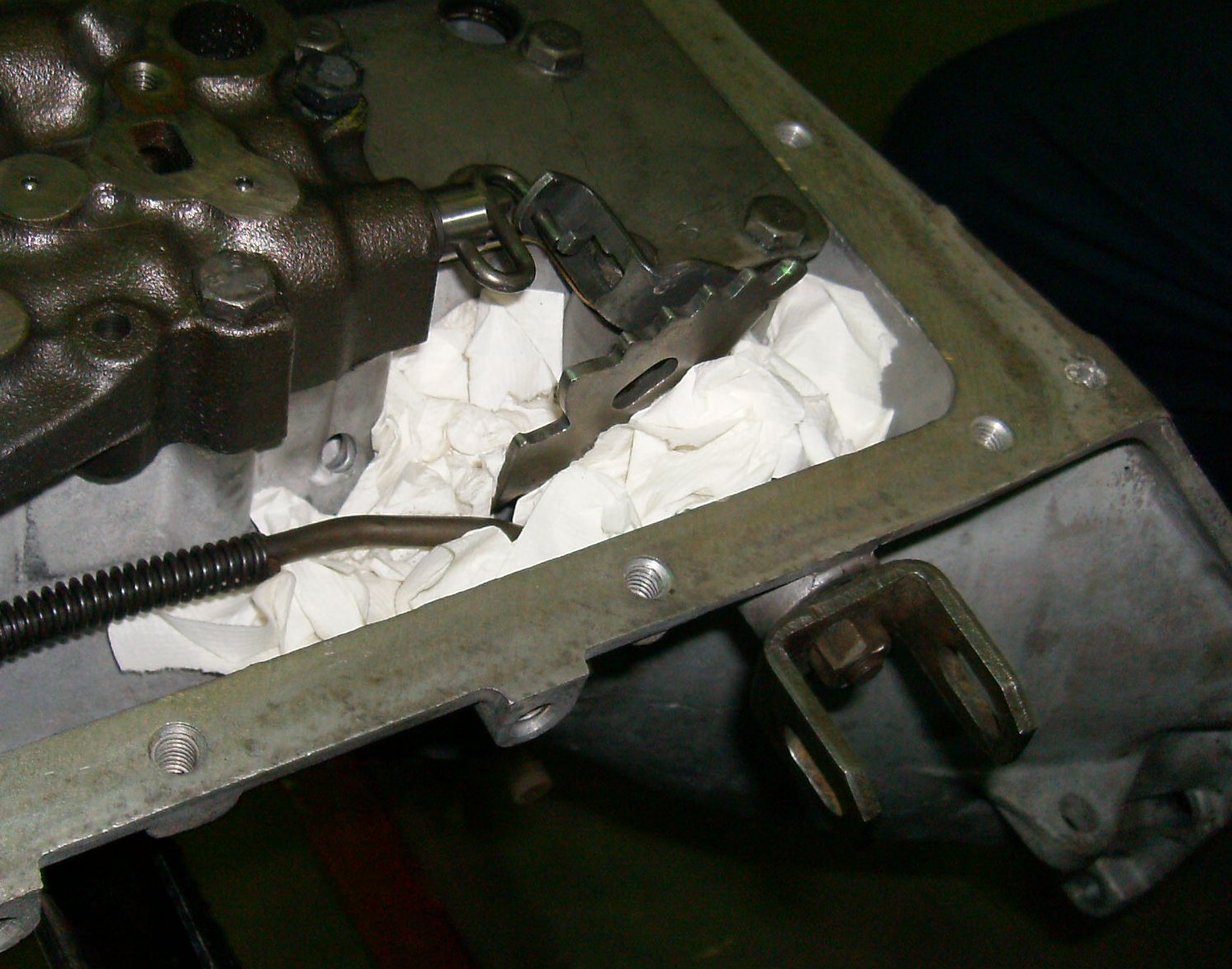
This time we took precautions!

Now Tommy can torque the valve body down.

No parts left over, we must be done!