A Short Course in External Ballistics
Retrieved: 11/18/2013
There is a lot of misleading information and myth flying around ("bull- istics") on the subject of the external ballistics. The tables below will hopefully shed some light on how that bullet really travels once you've pulled the trigger. All tables are rounded to the nearest 10 feet per second and drops are rounded to two places, unless I am trying to show small increments. Greater precision is meaningless in the "real" world. Even for the best of marksman a 1/2 minute of angle difference is effectively meaningless at realistic ranges. The majority of information is presented on rifle cartridges but the principles hold true for shotgun and pistol as well.
Remember Fr. Frog's Rules of External Ballistics:1) There ain't no magic bullets! (Although some are better than others for a particular purpose.)
2) Divide the range at which someone claims to have shot their deer by 4 to get the real range.
3) Always get as close as possible.
4) Don't believe manufacturer's claims.
5) Velocity erodes, mass doesn't.
6) In the battle between velocity and accuracy, accuracy always wins.
7) Inconsequential increments are meaningless.
8) Most gun writers are pathological liars.
Many people believe that bullets fly in a straight line. This is untrue. They actually travel in a parabolic trajectory or one that becomes more and more curved as range increases and velocity drops off. The bullet actually starts to drop when it leaves the firearm's muzzle. However, the centerline of the bore is angled slightly upward in relation to the line of the sights (which are above the bore) so that the projectile crosses the line of sight on its way up (usually around 25 yards or so) and again on its way down at what is called the zero range.
Terms relating to external ballistics include:
Back Curve - This is that portion of the bullets trajectory that drops below the critical zone beyond the point blank range. Past this point the trajectory begins to drop off very rapidly with range and the point of impact becomes very difficult to estimate.
Ballistic Coefficient - This is a number that relates to the effect of air drag on the bullet's flight and which can be used to later predict a bullet's trajectory under different circumstances through what are called "drag models." Technically a drag models applies only to a particular bullet, so using them to predict another bullet's performance is an approximation--but the results can be very close if the proper drag model is used. The most commonly used drag model is the G1 model (sometimes referred to--not really correctly--as C1) which is based on a flat-based blunt pointed bullet. The "standard" bullet used for this model has a ballistic coefficient of 1.0. A bullet that retains its velocity only half as well as the model has a ballistic coefficient of .5. The G1 model provides results close enough to the actual performance of most commercial bullets at moderate ranges (under about 500 yards) that it is commonly used for all commercial ballistics computation.
Note that there are two "standard" sets of meteorological conditions in common use. conditions" refer to an assumed used to standardize computations. The older one, is known as "Standard Metro" or "Army Standard" and the more modern "standard" is called the International Civil Aviation Organization (ICAO) standard. The characteristics of these two "standards" are listed below.
Standard                Metro           ICAO
-------------------     --------------  --------------
Altitude                Sea level (0')  Sea level (0')
Temperature             59deg F         59frh F
Barometric pressure     29.5275" Hg     29.9213" Hg
Humidity                78%             0%
While they are similar, the different parameters do have a slight affect on calculations and in effect change the standard atmospheric density by about 1.8 percent. Under ICAO conditions the speed of sound 1116.5 f/s and under Standard Metro conditions it is 1120.27 f/s.
Since a quoted ballistic coefficient depends on atmospheric density, the same bullet has two different BCs depending on the conditions used. If a quoted BC based upon the "Standard Metro" conditions is used in a ballistics program based upon the ICAO standard the BC needs to be modified by multiplying it by .982. Conversely, ICAO based BCs need to be multiplied by 1.018. While this is a very small change and has little effect at short (under 600 yards) range it does have an effect at long ranges. The table below gives what various manufacturers use.
Mfgs        BC Basis
Berger      ICAO
Barnes      Std Metro
Hornady     Std Metro
Nosler      ICAO
Remington   No Info received. Probably ICAO
Speer       They don't know.  They use "local conditions"
Sierra      Std Metro
Woodleigh   No Info received. Probably Std Metro
Winchester  Std Metro
A word to the wise. Many manufacturer give rather generous BCs for their bullets because: a) they want to look good--high BCs sell bullets; b) they were derived by visual shape comparison rather than actual firing data; or c) they were derived from short range firings rather than long range firings (which are more difficult to do). You should confirm your calculations by actual firing if you require exact data. Several manufactures have recently "readjusted" some of their BCs to more closely conform to actual firing data. For a more in-depth discussion of ballistic coefficients see the section below.For a listing of BCs in Excel spreadsheet format, click here.
Bore Centerline (Line of the bore) - This is the visual line of the center of the bore. Since sights are mounted above the bore's centerline and since the bullet begins to drop when it leaves the muzzle the bore must be angled upwards in relation to the line of sight so that the bullet will strike where the sights point.
Bullet Trajectory - This is the bullet's path as it travels down range. It is parabolic in shape and because the line of the bore is below the line of sight at the muzzle and angled upward, the bullet's path crosses the line of sight at two locations.
Critical Zone - This is the area of the bullet's path where it neither rises nor falls greater than the dimension specified. Most shooters set this as +/- 3" to 4" from the line of sight, although other dimensions are sometimes used. The measurement is usually based on one-half of the vital zone of the usual target. Typical vital zones diameters are often given as: 3" to 4" for small game, and 6" to 8" for big game and (Gasp!) anti-personnel use.
Drag Model - A mathematical representation of the velocity decay of a projectile of a specific shape. Note that the decay is non-linear. Now coming into use are "drg" files the describe the bullet's drag at different velocities and which allow ballistic computations that don't need a BC and that use only simple math. The down side is that they require a specific "drg" file for each bullet and the data in the file must generally be determined on a Doppler radar range, although a close approximation can be computed by analysis of the bullet's dimensions.
Drop - The distance a bullet falls below the line of the bore (at 90 deg to the line of the bore) when the bore is horizontal. Frequently mis-used to mean the bullet path in relation to the line of sight.
Initial Point - The range at which the bullet's trajectory first crosses the line of sight. This is normally occurs at a range of about 25 yards.
Line of Sight - This is the visual line of the aligned sight path. Since sights are mounted above the bore's centerline and since the bullet begins to drop when it leaves the muzzle the bore must be angled upwards in relation to the line of sight so that the bullet will strike where the sights point.
Maximum Ordinate - This is the maximum height of the projectile's path above the line of sight for a given point of impact and occurs somewhat past the halfway point to the zero range and it is determined by your zeroing range.
Maximum Point Blank Range - This is the farthest distance at which the bullet's path stays within the critical zone. In other words the maximum range at which you don't have to adjust your point of aim to hit the target's vital zone. Unless there is some over riding reason to the contrary shots should not generally be attempted much past this distance. In the words of the Guru, "It is unethical to attempt to take game beyond 300 meters." If you do, you should write yourself a letter explaining why it was necessary to do so. An approximate rule of thumb says that the maximum point blank range is approximately your zero range plus 40 yards.
Mid-range Trajectory - This is the height of the bullets path above the line of sight at half way to the zero range. It does not occur at the same range as the maximum ordinate height which can be greater.
Minute of Angle (MOA) - A "minute" of angle is 1/60 of a degree which for all practical purposes equates to 1 inch per 100 yards of range. (Actually it's 1.044") Thus 1 MOA at 100 yards is 1 inch and at 300 yards it is 3 inches. The term is commonly used to express the accuracy potential of a firearm.
Path - The distance a bullet's trajectory is above or below the line of sight.
Zero Range - This is the farthest distance at which the line of sight and the bullet's path intersect.
A Little History
In 1881 Krupp of Germany first accurately quantified the air drag influence on bullet travel by test firing large flat-based blunt-nosed bullets. Within a few years Mayevski had devised a mathematical model to forecast the trajectory of a bullet and then Ingalls published his famous tables using Mayevski's formulas and the Krupp data. In those days most bullet shapes were similar and airplanes or missiles did not exist. Ingalls defined the Ballistic Coefficient (B.C.) of a bullet as it's ability to overcome air resistance in flight indexed to Krupp's standard reference projectile. The work of Ingalls & Mayevski has been refined many times but it is still the foundation of small arms exterior ballistics including a reliance on BCs.
The shape of the projectile used in the Krupp firings. It is 3 calibers long and has an ogival head with a 1.49 caliber radius.


Modern bullet designs. Much different than the Krupp bullet. Would you expect them to have the same drag characteristics?By the middle of the 20th century rifle bullets had become more aerodynamic and there were better ways to measure air drag. After WWII the U.S. Army's Ballistic Research Lab (BRL) conducted experiments at their facility in Aberdeen, MD to remeasure the drag caused by air resistance on different bullet shapes. They discovered air drag on bullets increases substantially more just above the speed of sound than previously understood and that different shapes had different velocity erosion due to air drag. In 1965 Winchester-Western published several bullet drag functions based on this early BRL research. The so-called "G" functions for various shapes included an improved Ingalls model, designated "G1". Even though the BRL had demonstrated modern bullets would not parallel the flight of the "G1" standard projectile, the "G1" drag model was adopted by the shooting industry and is still used to generate most trajectory data and B.C.'s. Amazingly, the "G1" standard projectile is close to the shape of the old blunt-nosed, flat-based Krupp artillery round of 1881!
The firearms industry has developed myriad ways to compensate for this problem. Most bullet manufacturers properly measure velocity erosion then publish B.C.'s using an "average" of the calculated G1 based B.C.'s for "normal" velocities. In other words, the only spot on the G1 curve where the model is correct is at the so-called "normal" or average velocity. These B.C.'s are off slightly at other velocities unless the bullet has the same shape, and therefore the same drag as the standard G1 projectile--few modern bullets do.
Some ballistic programs adjust the B.C. for velocities above the speed of sound, others use several B.C.'s at different velocities in an effort to correct the model. While these approaches mitigate some of the problem, B.C.'s based on G1 still cannot be correct unless the bullet is of the same shape as the standard projectile. Also, the change to air drag as a function of velocity does not happen abruptly. Drag change is continuous with only small variation immediately above or below any point along the trajectory. Programs that translate the Ingalls tables directly to computer or use multiple B.C.'s can produce velocity discontinuities when drag values change abruptly at pre- determined velocity zones. The resulting rapid changes to ballistic coefficient do not duplicate "real world" conditions. A BC based upon the correct drag model (which technically changes with every bullet) stays the same value. However, using a more modern drag model such as G7 the calculated ballistics comes closer to actuality than with the G1 and some manufacturers are beginning to supply G7 based BCs.
The Solution
Shooting software is finally appearing based on methods used in aerospace with drag models for different bullet shapes. Results are superior to traditional "G1 fits everything" thinking, but now shooters must learn B.C.'s are different for each model. Each bullet has a slightly different actual drag model and if the exact drag model for a particular bullet is used the BC does not change with changes in velocity. This could get cumbersome very fast with all the bullets on the market.. However, most bullets actual drag models come pretty close to matching one of the existing standard drag models as shown on the graph below so we can get by with one of them and come much closer to real life performance than with the catch-all G1/Ingalls. Note that if the correct drag model is used (which technically is different for each bullet) the BC does NOT change with velocity, and if a drag model is used that more closely matches the actually drag model the BC will show less of a change at different velocities than using a badly matched (G1) drag model.
This is a scary proposition for most bullet companies who know many shooters pick bullets based only on their B.C.'s. For example, A boat tailed bullet with a G1 based B.C. of .690 may actually have a G7 based B.C. of only .344, since the G7 drag model much more accurately describes its performance. But, everyone "knows" that .690 is "better" than .344. However, using the wrong drag model will yield trajectory data that indicates incorrect drop. Fortunately the differences only become important at very long range (>700 yards) but there is a difference. As an example the GI M80 Ball bullet (149 gr FMJ boat tail) has a verified G7 BC of .195. The commercial equivalents of this bullet are listed as having a G1 BC of between .393 and .395. You can see the differences in the plotted trajectories using both the G1 and G7 values and a program that handles both types.
        G1 = .393    |  G7 = .195
Range   Vel.    Path |  Vel.    Path
---------------------|--------------
0       2750    -1.5    2750    -1.5
100     2522    4.8     2520    4.9
200     2306    5.70    2302    5.7
300     2100    0.00    2094    0.00
400     1905    -13.6   1898    -13.7
500     1722    -36.8   1710    -37.0
600     1553    -71.8   1530    -72.3
700     1401    -121.3  1360    -122.6
800     1269    -188.4  1200    -191.7
900     1161    -277.2  1074    -285.1
1000    1078    -391.8  1014    -408.4
Modern ballistics uses the coefficient of drag (C.D.) and velocity (actually
the bullet's Mach number rather than the traditional Ingalls/Mayevski/Sciacci
s, t, a & i functions. This avoids velocity discontinuities and when combined
with a proper drag model is far more accurate to distances beyond 1000 yards.
A by-product of modern ballistics research is that the C.D. can be estimated
fairly accurately from projectile dimensions and used to define custom drag
models for unusual bullet shapes. (See caveat below.)The drawing below shows how the various drag models vary.
Note the difference between the G1 and the G5, G6, and G7!
Another term occasionally found in load manuals is a bullet's "Form Factor". The form factor is simply the C.D. of a bullet divided by the C.D. of a pre- defined drag model's standard projectile.
Ballistic Coefficients are just the ratio of velocity retardation due to air drag (or C.D.) for a particular bullet to that of its larger 'G' Model standard bullet. To relate the size of the bullet to that of the standard projectile we simply divide the bullet's sectional density by it's form factor.
The following are the most common current drag models used in ballistics:
G1.1 - Standard model, flat based pointed bullet - 3.28 calibers in length, with a 1.32 caliber length nose, with a 2 caliber (blunt) nose ogiveTo see what shapes these drag models are based upon, click here.G2 - Special model for a long conical point banded artillery projectile - 5.19 calibers long with a .5 caliber 6° boat tail. Not generally applicable to small arms.
G5.1 - For Moderate (low base) boat tails - 4.29 calibers long with a .49 caliber 7deg 30' boat tail with 2.1 caliber nose with a 6.19 caliber tangent nose ogive
G6.1 - For flat based "spire point" type bullets - 4.81 calibers long with a 2.53 caliber nose and a 6.99 caliber secant nose ogive
G7.2 - For "VLD" type or pointed boat tails - 4.23 calibers long with with a .6 caliber long 7deg 30' Tail Taper and a 2.18 caliber long nose with a 10 caliber tangent nose ogive. Most modern US military boat tailed bullets match this model.
G8.1 - Flat base with similar nose design to G7 - 3.64 calibers long with a 2.18 caliber long nose and a 10 caliber secant nose ogive. The US M2 152 gr .30 cal bullet matches this drag model. Close to the G6 model.
GS - For round ball - Based on 9/16" spherical projectiles as measured by the BRL. Larger and smaller sphere characteristics are effectively identical.
RA4 - For 22 Long Rifle, identical to G1 below 1400 f/s
GL - Traditional model used for blunt nosed exposed lead bullets, identical to G1 below 1400 f/s
GI - Converted from the original Ingalls tables. Essentially G1
GC - 3 caliber long flat nosed cylinder. Identical to G1 below 1200 f/s
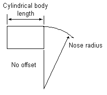
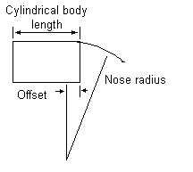
Nose Shapes
There are two basic types of nose shapes used on pointed bullets. Tangent nose and secant nose. A tangent nose shape has a radius the blends smoothly with the cylindrical portion of the bullet's body, that is the radius used has its center point on a line that is tangent to (at right angle to) the start of the cylindrical body. With a secant nose shape the center point of the radius of the nose is offset some distance from the start of the cylindrical body. Secant nose shapes are ballistically more efficient but can cause issues with bullet seating depth and standoff from the barrel's lands. The are also some "hybrid" designs that combine both secant and tangent radii.
Accurate B.C.'s are crucial to getting good data from your exterior ballistics software. A good ballistic program should be able to use two velocities and the distance between them to calculate an exact ballistic coefficient for any of the common drag models. While you should really simultaneously measure the velocities at the 2 points you can do very good work by measuring a minimum of 5 shots at the near and far ranges and average each group.
This method of calculating a B.C. is preferred for personal use and can be used to duplicate published velocity tables for a bullet when the coefficient is unknown or to more accurately model trajectories achieved from your own firearm. A lot has changed in shooting software. If your software is more than two years old, chances are it does not employ the latest modeling techniques or calculate B.C.'s and even some of the newest software is not perfect as you can see from the next section.
If the industry wants to stay with a single BC drag model with modern bullets they would probably be better off using the G7 model than the G1. While not necessarily a perfect match the characteristic of modern bullets are much closer to the G7 drag model than the G1.
To order RSI's Shooting lab software you can go to www.shootingsoftware.com. Please tell him Fr. Frog sent you.
Effects Of Change In BC.
Small changes in BC value have very little effect until the ranges get past 5 - 600 yards.
Range in Yards  Absolute Drop  Absolute Drop
                G7 BC = .195   G7 BC = .200
--------------  -------------  -------------
100             2.44           2.43
200             10.4           10.3
400             47.3           47
600             123.7          122.1
800             260.5          255.8
1000            494.7          482.6
Bullet pictures courtesy Hornady Mfg.
An elongated bullet, as opposed to a round ball, is inherently unstable aerodynamically. When made stable gyroscopically by spinning, its center-of- gravity will follow the flight path. However, the nose of the bullet stays above the flight path ever so little just because the bullet has a finite length and generates some lift. This causes the bullet to fly at a very small angle of attack with respect to the flight path. The angle of attack produces a small upward cross flow over the nose that results in a small lift force. The lift force normally would cause the nose to rise and the bullet to tumble as the nose rose even more. That is where the spin comes in and causes the rising nose to precess about the bullet axis. When the spin is close to being right for the bullet's length, the precessing is minimized and the bullet "goes to sleep" If it is too slow the bullet will not be as stable as it should. (That is why Jeff Cooper says it's wrong to shoot groups at 100 yards for accuracy testing and suggests 300 yards. If your twist isn't right for the bullet used your group size will be larger at long ranges than would be expected by extrapolation of 100 yard data due to bullet wobble.) VLD (very low drag) bullets are very susceptible to precession and don't show their best accuracy until the get to 2-300 yards.
Of course, any other disturbing force such as a side wind gust could cause a difference in bullet nose precession but the effect would be quite small for a properly spin stabilized bullet. Most of the lift force is on the nose of the bullet and is proportional to the square of the bullet velocity as well as the nose shape and length. The new long-nosed bullets for long range match shooting can generate quite a bit more lift occurring farther ahead of the center- of-gravity and can produce a nasty pitch-up moment. That is why they require a faster than normal twist to stabilize them. Pistol bullets, being relatively short and with little taper to the nose, require a slower spin for stability.
Let's look at the rotational speed of a bullet. The formula for computing the rotational speed of a bullet is
R = (12/T) * V
where
T = Twist
V = Velocity in f/s
R = Rotations per second
R * 60 = Rotations per minute
Now consider a bullet chronographed at about 2750 f/s muzzle velocity fired from a rifle with a 10" twist. It is rotating at around 198,000 rpm Let the flight velocity decay to 2000 f/s. Now what is the bullet rotational speed? Well, it doesn't fall off much because the only things slowing it down are inertia and skin friction drag which is pretty low, and with the M80 ball bullet it has been measured about 90 percent of the original rpm (or in this case about 178,00 rpm) depending on the bullet. Then chronograph an identical bullet from the same rifle, this time with a muzzle velocity of 2000 f/s. Its rotational velocity will be 144,000 rpm. Its stability will be different from the bullet fired at 3000 f/s and allowed to slow down to 2000 f/s. It will not have the same drag at 2000 f/s although the bullets are identical. Therefore, two identical bullets fired from the same rifle at different velocities, will not have the same drag coefficient or ballistic coefficient just because of the way the measurements were taken. There are times when test data does not mean what you think it does. Again, radar range testing is the only way to fly for trustworthy bullet drag data. [I am indebted to Lew Kenner for this lucid description of bullet stability.]
Below is the rotational decay characteristic of the M80 Ball bullet which is typical.
Range           Muzzle  100     200     300     400     500     1000

Percent of
spin remaining  75      100     98      96      93      91      89
Bullet RPM      198,000 194,000 190,000 184,000 180,000 176,000 148,500
Another factor is that it is not necessarily true that the drag coefficient of a particular bullet is proportional to that of another bullet of the same design across the Mach number range, but this is what a ballistic coefficient assumes.
Something else to worry about is the effect of the bullet tip shape/condition on the ballistic coefficient. Because modern bullet have soft points they are subject to damage and manufacturing tolerances that can alter the BC from bullet to bullet and across otherwise similar bullets, although this affect is small unless there is a great deal of deformation.
For truly accurate results, individual bullet characteristics need to be measured on Doppler radar ranges as is done by the military--much too expensive a procedure for the commercial bullet industry who doesn't really care about great accuracy in BC calculations--and the drag model from those measurements applied only to the particular bullet tested. (If you have a spare $100,000 + and would like to buy me such a setup, let me know.)
The good news is that for normal rifle ranges the drag coefficients and ballistic coefficients can work satisfactorily for most purposes--so let's proceed.
Continuing our discussion of external ballistics let's look at what bullets do under different conditions and see what affects what. While the majority of the discussion below deals with rifles projectiles, the principles apply to shotgun and pistol projectiles as well. I suggest that you read the rifle section first. If you pay attention you will see that many effects are quite small and have no real affect at reasonable ranges. Too many people worry about inconsequential increments. I had one fellow brag to me that a certain load gave him less drop (according to published data) than the brand he had been using. According to the published data the difference amounted to less than 2" at 500 yards. Huh? (And, he was hunting deer in the NY woods.) If you are one of those rare people that really can hit consistently at extremely long ranges you may have some things to think about. For the majority of shooters, however, what happens inside of 300 yards is what really matters.
By the way, most folks tend to visually over estimate the range and think that something is farther off than it is. If you have never done range estimation, try this. Find a large open field and laser or measure off a real 400 or 500 yards and then turn around and look at your buddy standing at the start point. If you don't have a laser or long tape measure simply find a long straight road, set your odometer to 0 and then drive. Each 1/10 of a mile is 176 yards.
Please note that this a fairly long page with lots of tables and runs about 21 screens worth at 800 x 600 screen resolution, so you might want to print it out (landscape orientation works best). MS FrontPage says 68 seconds to load at 28.8.
A NOTE: As previously mentioned the drag models for G1 and G7 can't really be compared. However, the G1 "equivalent" for the M80 type bullet is about .397 according to the published data for the Hornady and Sierra FMJ-BT 150 gr bullet and this number will provide a fairly close match of trajectory for ranges under about 500 yards. For other bullets use your ballistics software to determine what works best for you.
However, for those with the skill (which are few and far between) to make use of improved trajectory and wind drift (which we'll discuss later) at greatly extended ranges the extra velocity can provide an edge. For the vast majority of shooters it is a moot point.
Range Velocity Bullet         Velocity Bullet        Velocity Bullet
                Path                    Path                   Path
----- -------- ------         -------- ------        -------- ------
0       2500    -1.5            2700    -1.5            2900    -1.5
25      2450    0.3             2640    .1              2840    -.1
50      2390    1.7             2580    1.3             2780    1.0
75      2340    2.8             2530    2.2             2720    1.8
100     2280    3.4             2470    2.8             2660    2.3
125     2230    3.7             2420    3.0             2600    2.5
150     2180    3.5             2360    2.9             2550    2.4
175     2130    2.8             2300    2.4             2490    1.9
200     2080    1.6             2250    1.4             2440    1.1
225     2030    0               2200    0               2380    0
250     1980    -2.1            2150    -1.8            2330    -1.5
275     1930    -4.8            2100    -4.2            2270    -3.5
300     1880    -8.1            2050    -6.9            2220    -5.9
325     1830    -12.0           2000    -10.3           2170    -8.7
350     1780    -16.6           1950    -14.0           2120    -12.0
400     1690    -28             1850    -23             2020    -20
450     1602    -42             1760    -35             1920    -30
500     1510    -60             1670    -50             1820    -43
550     1430    -82             1580    -68             1730    -58
600     1340    -107            1490    -91             1640    -76
                 Bullet             Bullet             Bullet
                 Path               Path               Path
Range Velocity   210     Velocity   225     Velocity   240
                 yard               yard               yard
                 zero               zero               zero
----- --------   ------  --------   ------  --------   ------
0       2500     -1.5      2700    -1.5      2900     -1.5
25      2450      0.2      2640      .1      2840      0
50      2390      1.5      2580     1.3      2780      1.1
75      2340      2.4      2530     2.2      2720      2.0
100     2280      3.0      2470     2.8      2660      2.6
125     2230      3.1      2420     3.0      2600      2.9
150     2180      2.7      2360     2.9      2550      2.9
175     2130      1.9      2300     2.4      2490      2.5
200     2080      0.6      2250     1.4      2440      1.9
225     2030     -1.1      2200      0       2380      0.8
250     1980     -3.4      2150    -1.8      2330     -0.6
275     1930     -6.2      2100    -4.2      2270     -2.5
300     1880     -9.6      2050    -6.9      2220     -4.8
325     1830     -13.6     2000   -10.3      2170     -7.8
350     1780     -18.4     1950   -14.0      2120    -10.7
400     1690     -30       1850   -23        2020    -18.5
450     1602     -45       1760   -35        1920    -28
500     1510     -62       1670   -50        1820    -41
550     1430     -84       1580   -68        1730    -56
600     1340    -110       1490   -91        1640    -74
The table below shows the effect of different zeroing ranges. You can see that a good zeroing range for the .308 / 150 gr is somewhat greater than 200 yards. (200 meters might be a workable choice but 225 - 250 yards works very well) Looking at the first set of tables (above) with the 225 yard zero you can confirm this. This data holds true for most other cartridges of similar bullet weight and velocity. For a more in depth discussion of zeroing visit the Zeroing Page by returning to the main ballistics menu page. (I suggest that you read all these ballistics pages in the order suggested for maximum benefit.)
Effect of different zeroing ranges on trajectory
(Muzzle velocity = 2700 f/s)

Range   Zero = 100      Zero = 200      Zero = 300
-----   ----------      ----------      ----------
0       -1.5            -1.5            -1.5
25      -0.6            -0.1             0.6
50      -0.1             0.9             2.5
75       0.1             1.7             3.9
100      0               2.1             5.1
125     -0.5             2.2             5.9
150     -1.3             1.8             6.4
175     -2.5             1.1             6.4
200     -4.2             0               6.0
225     -6.3            -1.6             5.2
250     -8.8            -3.6             3.9
275    -12              -6.1             2.2
300    -15              -9.0             0
325    -19             -13              -2.7
350    -24             -16              -5.9
400    -35             -26             -14
500    -64             -54             -39
600   -107             -95             -77
Note that until the bullet gets way out past Ft. Mudge that a nominal 15% change in ballistic coefficient doesn't do very much. (Yup! You read it right. At 1000 yards with a 225 yard zero you've got to hold between 31 and 35 feet high to hit your target.)
Effect of ballistic coefficient on trajectoryRange Vel (G1=.40) Bullet Path Vel (G1=.46) Bullet Path ----- ------------ ----------- ------------ ------------ 0 2700 -1.5 2700 -1.5 100 2480 2.8 2510 2.7 200 2270 1.4 2320 1.3 300 2070 -6.8 2140 -6.6 400 1880 -23 1970 -22 500 1700 -50 Ft. Mudge 1810 -46 600 1540 -88 1660 -82 700 1390 -140 1520 -130 800 1260 -210 1390 -190 900 1160 -310 1280 -270 1000 1070 -430 1180 -380
The effect is quite small and varies with the shape and depth of the cannelure and seems to vary between about 3 and 12 percent. The table below shows the difference between several bullets that are identical except for a cannelure.
       Bullet                G1 BC            G1 BC
                         (no cannelure)  (with cannelure)
--------------------     --------------  ----------------
140 gr .264 boattail          .550            .520

162 gr .280 boattail          .625            .570

168 gr .308 boattail          .475            .447
For example, at higher altitudes the air is thinner so there is less drag on the bullet. However, it is also true that at higher altitudes the air is generally colder, the speed of sound is thus lower, and therefore transonic drag occurs at a lower velocity. Also, on a warm day the barometric pressure tends to be higher which increases drag but the higher temperatures tend to decrease drag slightly. In effect most things tend to pretty much cancel each other out--but not quite.
The following tables assume the standard M80 ball ammo at 2700 f/s with a 225 yard zero as used in the first table above (all of which were done for "standard" conditions). They will give you some idea of what the various changes will do independently. In each table below only the particular item has been changed. The other conditions remain at "standard."
Altitude Changes

Bullet Path in Inches (225 yd Zero)

        -----------altitude-------------
Range   Sea Level 1000ft  5000ft 10,000ft
-----   --------- ------  ------ --------
0         -1.5    -1.5    -1.5    -1.5
100        2.7     2.7     2.7     2.5
200        1.4     1.4     1.3     1.2
300       -6.9    -6.9    -6.6    -6.2
400      -23     -23     -22     -21
500      -50     -49     -46     -43


Temperature Changes

Range   Standard
          (59 F)  (32 F)  (80 F)
-----   --------  ------  ------
0         -1.5    -1.5    -1.5
100        2.7     2.8     2.7
200        1.4     1.4     1.4
300       -6.9    -7.1    -6.9
400      -23     -24     -23
500      -50     -52     -49
Since the effect of temperature changes on internal ballistics is difficult to predict the only way to get accurate data for temperature variances is to actually test the load in question under the conditions expected.
        drop       drop         drop
        standard   NJ           AZ
range              10' ASL 31F  5300 ASL 90F
-----   --------   -----------  ------------
0         -1.5    -1.5         -1.5
100        2.7     2.8          2.6
200        1.4     1.4          1.3
300       -6.9    -7.1         -6.4
400      -23     -24          -21
500      -50     -52          -45
Effect of changes in bullet weight on trajectory, 225 yard zero

Range   150gr   Bullet     165gr   Bullet     180     Bullet
      (G1=.358) Path     (G1=.400) Path     (G1=.431) Path
----- --------- ------   --------- ------   --------- ------
0       2820    -1.5       2700    -1.5       2620    -1.5
100     2570     2.5       2480     2.8       2420     3.0
200     2300     1.3       2270     1.4       2230     1.4
300     2100    -6.5       2070    -6.8       2040    -7.1
400     1890    -22        1880    -23        1860    -24
500     1690    -48        1700    -50        1701    -51
600     1510    -85        1540    -88        1548    -90
700     1350    -140       1390    -141       1410    -144
800     1210    -212       1260    -213       1290    -216
900     1110    -310       1160    -308       1180    -309
1000    1030    -436       1080    -429       1100    -428
The final thing we'll look at is wind induced drift. To keep things manageable we'll look at the effect of both velocity and ballistic coefficient in this table. We'll use the same commercial 165 gr flat base and boat tail bullets with G1=.400 and .460 as before.
Drift in inches for a 10 mph (90 deg) crosswind*
Flat Based / Boat Tail

Range   MV=2500   MV=2700   MV=2900
-----   -------   -------   -------
0       0/0       0/0       0/0
100     .95/.81   .85/.71   .82/.71
200     4.0/3.5   3.5/3     3.2/2.8
300     9.3/8.1   8.4/7.2   7.6/6.5
400     18/15     15/13     14/12
500     29/25     26/22     23/20
600     44/37     39/33     35/29
700     62/52     55/46     50/42
800     84/71     76/63     68/57
900     110/93    100/83    91/75
1000    140/117   128/106   117/96

* For 45deg crosswind use 3/4 value
An addendum. I'm sure someone is going to ask, "How can you tell how fast the wind is blowing?" These rules of thumbs are taken from TC 23-4 on sniper training.
3 to 5 mph      Wind can just be felt on the face
5 to 8 mph      Leaves in the trees are in constant motion
12 to 15 mph    Small trees begin to sway
Another method of estimating wind velocity is by estimating the angle between a flag and its pole and dividing that angle by 4. If no flag is available a small piece of cloth, paper, or some grass may be dropped from shoulder height and the angle between vertical on your shoulder and where it lands can be estimated. There are also available nifty "wind speed meter" available for shooters. See www.kestrelmeters.com.
12ga Foster Type Rifled Slug (G1 = .109)
(20" barreled riotgun with ghostring sights)

                     Path       Path
Range   Velocity  Zero = 75  Zero = 100
-----   --------  ---------  ----------
0       1440        -1.0       -1.0
25      1320         0.7        1.4
50      1200         1.1        2.5
75      1120          0         2.1
100     1050        -2.8         0
125     1000        -7.5       -4.0
150     960        -14.4      -10.2
By the way, for those of you interested in such things (even though at typical buckshot distances it doesn't matter) the ballistic coefficients for buckshot are approximately as follows. Note that the GS drag model should be used for spherical projectiles but since most programs don't handle the GS model I have converted them to the approximate G1 figures.
Size    Diam    Wt      BC (GS) BC (G1)
----    ----    --      ------- -------
0000    .378    87      .087    .057
000     .36     71      .078    .052
00      .33     54      .071    .047
0       .32     48      .067    .045
1       .30     40      .063    .042
4       .24     20      .050    .033
The following is the data for 00 buckshot. A 75 yd "zero" is assumed.
00 Buckshot Trajectory (GS =.071)

Range   Velocity  Path
                  Zero = 75
-----   --------  ---------
0         1290      -1.5
25        1050       1.1
50        930        1.9
75        840         0
100       770       -5.2
125       710      -15
150       610      -30
Typical Handgun Ammunition Trajectories

Range   9 mm 125 gr  .357 158 gr  .45 230 gr
-----   -----------  -----------  ----------
0          -0.8         -0.8        -0.8
25          0.5          0.4         1.1
50           0            0           0
75         -2.5         -2.1        -4.2
100        -7.1         -6.1       -11.5
125       -14.0        -12.1       -22.0
Maximum Horizontal Range
Maximum horizontal range is defined as the maximum distance a projectile will travel over level ground. This distance depends upon muzzle velocity, barrel elevation, distance of the muzzle above ground level, and bullet design. For computational purposes the distance is computed at the line of sight as at the typical distances of a barrel above ground level the difference at the actual ground would be slight.
In a vacuum a firearm would achieve its absolute maximum range at an elevation of 45deg. However, with typical small arms projectiles the effect of air resistance is so great that maximum range is usually obtained at a departure angle of between 29deg and 35deg. The table below gives the calculated approximate absolute maximum ranges for some common rounds using modern drag modeling techniques at standard sea level conditions, and a not so common projectile. It may differ from some previously published data based on older methods of computation. The data indicated by "#" is from government firing tables.
Note that all this data assumes point forward flight during the entire trajectory and is based upon "standard" conditions. However, this may in fact not be the case--see the article on vertically fired projectiles, above-- except for the M829 "dart" which is fin stabilized. While this data is sound one should not consider the data to hold for all cases and conditions-- especially when considering range safety implications. Changes in projectile stability, elevation above sea level, temperature, barometric pressure, humidity, and wind speed and direction at both ground level and at altitude can contribute to wide variances (10 to 15 percent in either direction).
Cartridge       Max Range (yds)
-------------- ----------------
.22 RF (40gr)        1530#
.223 (M193)          3390#
.223 (M855)          3760#
243 (100gr)          4750
.264 Win (140)       5130
7mm Mag (175gr)      5420
(180 gr)             1800
.30-30 (170gr)       2490
.308 (M80)           4480#
.308W (M118)         5780#
30-06 (180gr)        5320
30 M2 Ball           3500#
12 ga Slug           1200
.300W Mag (200gr)    5930
9 mm M882            1970#
.38SPL +P (158gr)    1780
.357 (158gr)         1950
.45ACP M1911 (230gr) 1850#
.40S&W (180 gr)      1800
375H&H (270gr)       3370
.45-70 (500gr)       3220
.458W (500gr)        3620
.50 BMG AP M2        6670#
M903 SLAP            8700#
120mm M829 APDS      113,000 @ 55 degrees#

# From government firing tables
Shot Size  Maximum range
---------  -------------
12         110
71/2       209
4          286
BB         396
4 Buck     528
00 Buck    726
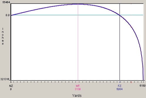
There is also another "maximum distance" which is the range at which the bullet starts to fall straight down with no "forward" velocity, as if fired from a tall mountain or an aircraft. While pretty much an impractical solution, this is the absolute maximum range that is possible for the projectile to achieve.
In the graphic below the projectile has a level ground maximum rage of 5084 yards. However, if fired from an aircraft flying at some 27,000 feet above ground the bullet would reach vertical free fall after traveling 6180 yards (dropping 321316 inches (8925 yards) below the line of sight).
To quote Robert Heinlein, "There are no deadly weapons, only deadly men."
Ballisticard Systems
P.O. Box 74
Atascadero, CA 93423
805.461.3954
ballistic(at)tcsn(dot)net
http://www.ballisticards.com
Please mention this site if you contact them.
I hope all this information has been of some help and that you've learned not to sweat the small stuff. The other thing I hope you have gotten out of all this is that for truly accurate results you need to test your stuff where you use it.