A Ball Mill
Retrieved: 12/28/2014
I approached this project the patient way and started by first ordering the milling bible entitled "Ball Milling Theory and Practice for the Amateur Pyrotechnician" by Lloyd Sponenburgh. I have not faithfully followed his plan, nor do I expect you will follow mine. However, for those of you who are dying to build your mill without buying the book, this page illustrates the general approach.
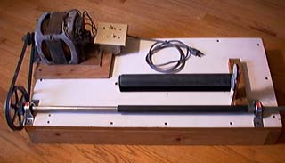
have pictured the entire mill here for visual reference as you look at the remaining illustrations.
First, you have to decide what kind of frame to mount your mill on. I simply made a rectangle with 2 X 4's and screwed two layers of 1/2 inch plywood on top. Lloyd's plan gives all the patterns to build a nice milling cabinet with its own stand. Follow this link to see a picture of a mill built more closely to the Sponenburgh plan. Whatever you use, it must be very sturdy!! These mills must endure heavy vibration and weight loads.
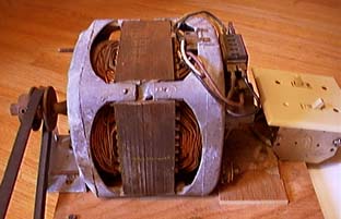
The electric motor should be a 1/3 to 1/2 horsepower, capacitor-start, 1725 rpm, 115v motor. You can get one from Grainger using part # 6K758. In my case, I am using a motor salvaged from a washing machine for which I paid $10. Since it has coils for 2 speeds, I used 2 switches. One switches between hi and low speed and the other is the on/off switch. It turned out that I only use the fast speed, so the speed switch is superfluous. The shaft sheave on the motor should be 2 inch o.d. by 1/2 inch (Grainger #3X895).
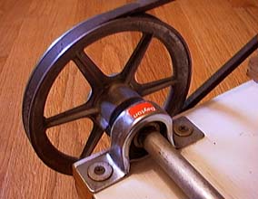
The drive shaft for the mill is 5/8 inch round steel bar stock. These can be purchased at any hardware store. Be sure it is perfectly straight. The sheave on the drive shaft is a 6 inch o.d. by 5/8 inch (Grainger #3X919). This cost me $3.72. You will also need two self-centering ball-bearing pillow-block bearings to mount the drive shaft (Grainger #2X898). I had to sand the drive shaft a little bit to allow the bearings to slide onto the shaft.
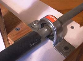
Before placing the bearings on the shaft, you need to place a piece of automotive heater hose on it as shown here. This hose is 5/8 inch i.d. by 7/8 inch o.d. It can be found at most hardware or auto parts stores. A little lubrication of some kind on the shaft will greatly aid the sliding on of the hose.
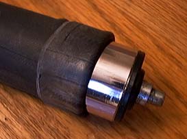
The other side of the mill jar cradle uses a ball bearing equipment roller. I bought this one at Woodworker's Warehouse for about $10. This picture shows the roller removed from its bracket. The roller has been covered with two layers of bicycle tire inner tube. The inner tube layers have been folded back in the picture for illustrative purposes only. You may be wondering how to get the inner tube layers over the roller. Again, Lloyd describes a technique which works very nicely.
Start with a 26 inch by 2 inch bicycle tire inner tube. Cut the deflated tube about 3 inches from the valve stem and tightly tie a cord around each end so the tube can be inflated to look like a long three inch diameter sausage. The trick is to push the roller end into the end of the inflated inner tube. When the roller is completely enclosed by the inner tube with a few inches of overlap, you can cut the sausage off near the valve stem to allow it to deflate. You now have two layers of rubber over the roller which are connected at one end. After allowing the rubber to relax a little bit, you can now trim the ends with scissors to within 1/4 inch of the ends of the roller. Now re- install the roller in its bracket and check for unimpeded rotation.
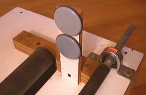
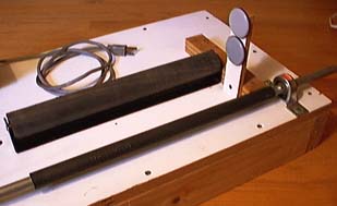
If you mount the drive shaft and equipment roller perfectly parallel, your mill jar may not creep as it rolls in the cradle. To be safe, I installed this bumper to prevent the mill jar from exiting its cradle. I used two Teflon furniture slides on the bumper to allow the mill jar to slide against the bumper with little friction. The drive shaft and equipment roller are mounted with 3 inches of space between them to accommodate both a 4 inch and 5 inch mill jar. A 6 inch mill jar requires a space of 4.5 inches.
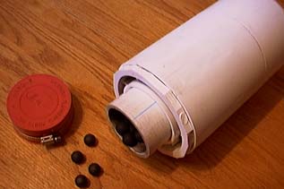
This is a mill jar which has been constructed from 5 inch PVC pipe and fittings. The milling media is antimony hardened, 3/4 inch lead balls. The construction of the jars is relatively simple, but is a subject for another project page.
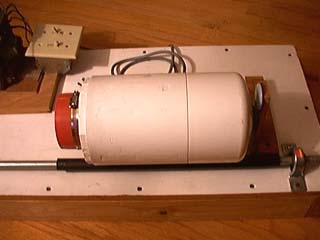
Finally, this shot shows the placement of the 5 inch mill jar in the cradle. With this setup, I can mill about 3 1/4 cups of high quality black powder in about 3 hours. The efficiency of this mill is dependent upon many factors which are explained in Lloyd's book. There is a wealth of information about milling theory contained in the book and I would highly recommend the serious pyrotechnician to purchase it. You can find it in the books and video http://www.skylighter.com/books.htm section of Skylighter's web catalog.
Date: Wed, 28 Oct 1998
From: "Lloyd E. Sponenburgh" (SPONENLE@columb20.dhec.state.sc.us)
I suggest that you provide some sort of shield for your motor so that milling dust cannot fall directly into the area of the centrifugal switch. That switch sparks severely during normal operation, and could cause an explosion if you had a prior jar leak.
That shield is provided as an artifact of the cabinet design in my mill.