The first batch is almost done, I am working on hold down clamps and hardware, trying to make sure it will work with a minimum of aggravation. I still need to make the stops that will be held down with a stud and T-nut arrangement that fits in the curved lower T-slot. The stops will aid in realigning the frame if it needs to be removed and replaced on the fixture, plus it will provide a certain amount of security against the frame moving while it is being machined.
I tried to get plenty of 1/4-20 tapped hold down holes, so where ever the frame is oriented it can be clamped securely and with a minimum of hassle. There are 3 locations for stepped dowels which fit in the slide stop hole. The stepped dowels can be moved around, and they will be available in various sizes to fit frames that have +/- holes.
The fixture will accept the frame in most positions with the grip bushings installed, for the vast the majority of operations it will not be an issue, there may some unusual positions where the bushing have to be removed. But for ramped barrel cuts, magwell work, rail work, feed ramp work, the bushings can stay on, as well as the plunger tube if it is placed toward the frame fixture.
John Harrison was gracious enough to supply pertinent dimensions for the smaller frames, and the fixture should accommodate them. I tried to make it so magwells would not cause problems, the Springfield magwell you see on the fixture has clearance to spare.
The back has T-slots machined into the plate, for mounting to angle plates if desired.
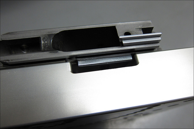
When the dowel is located as it is here the frame can be freely revolved around the slidestop hole (X0 and Y0 for dimensions). The grip bushings
When the dowel is located as it is here the frame can be freely revolved around the slidestop hole (X0 and Y0 for dimensions). The grip bushings will clear in all positions
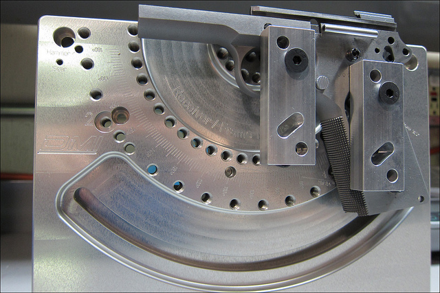

To answer the question posed by StrikerDown, the photo I put up on the gunsmith's tools thread
http://forums.1911forum.com/showthread.php?t=323024&page=2
Shows the front and some backs of the fixture.
I debated what color to do these in, and decided on a clear anodize instead of a colored anodize, I did do a couple in black that are going to Chuck W in NM. Our anodizing line is setup for small parts, and anodizing these clear is the best option for me right now. This anodizing gives a matt finish and brings out the metal grain, but it is hard and will stay nicer looking longer than the raw aluminum. Raw aluminum tends to get grit and small pieces of metal imbedded in it, and that would not be best for the finish on frames.
Here are some more pictures and descriptions. Some have asked for this, and I'll try to add as time permits. Many people will find this boring and redundant, but someone might learn something new.
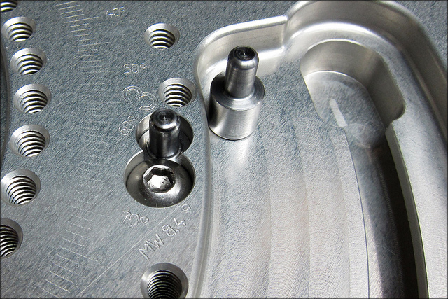
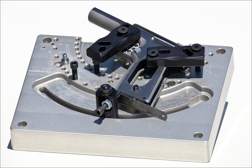
This shows the stepped dowel configuration, there are 3 locations. The reason they are stepped is so the dowel base and fixture plate can be uniform sizes, while the locating part of the dowel can vary according to needs, much like the interchangeable grips on a XD pistol. The reason there are 3 places to put the dowel is because as the frame is rotated around for various operations too much of the frame ends up off the fixture, and support and rigidity becomes "iffy". The reason there are dowels in the first place is: they aid in setup by fixing one point of the work piece (frame), and they add security against the frame moving under cutting force of the tool.
You might have noticed where MW 8.4 degrees is engraved, that is a setup mark to aid in magwell and etc. work.
The fixture back. The T-slots are for those who wish to optionally mount this to an angle plate. I have plenty of 7/16" T-nuts, studs, and flange nuts for anyone who want/needs them. Many people will probably stand this up in a machine vise, and use it that way. It's not as rigid, but for light cuts it's ok. It can also be placed flat on a mill table or in a mill vise.
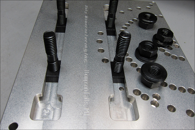
The T slots for the angle plates are a brilliant feature that makes the use of an angle plate a non issue! Much more sanitary than holes drilled for a specific hole spacing. Quite innovative and a nice touch!
I said I would post a photo of the 100% finished product, so for anyone interested here it is. The photo was taken in harsh sunlight, and the depth of field is narrow so only parts of the photo are in sharp focus, sorry. But, so far all of my photos have been snapshots, I haven't had the free time to set up for really nice shots.
I like it a lot...
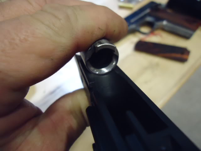
Before...
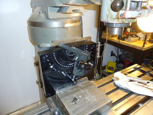
Set up...
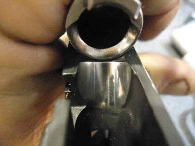
After... one perfectly ruined feedramp...
Well done and very useful. Makes set up a breeze..