I mostly just lurk here for the education and fine advice you folks have to offer but I have been building my first 1911 from the ground up and I just wanted to post a few of the tools that I have built to keep my Brownell's bill from getting out of hand.
Any comments, suggestions, or constructive (or destructive. I can take it. ) criticism is welcomed.
I think I'll build an extractor tuning fixture next!
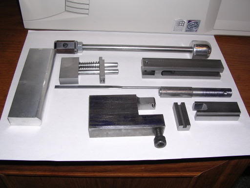
On the left is an aluminum mag well filler to keep the frame from being crushed when it is clamped in a vise.
Across the top is a lug iron. It is used to smooth or lower the slide locking lugs. You can just see a piece of emery cloth clamped in it on the left end.
Below the lug iron and to the left is a fixture to measure the distance from the breech face to the locking lugs. The small, rectangular piece is spring loaded and slides on the two dowel pins. It is locked in place with a set screw at the bottom.
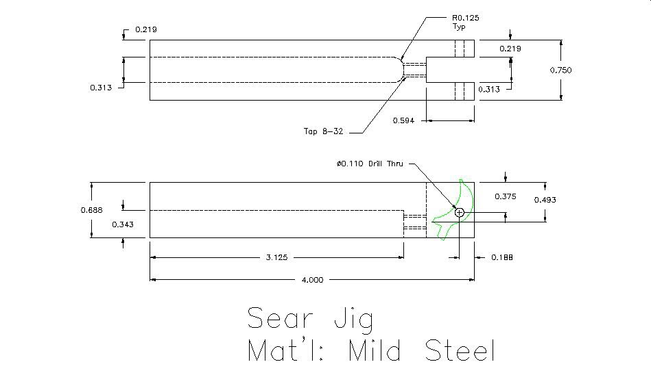
To the right of the lug measuring fixture is a sear jig. It has an adjusting screw at the bottom to adjust the angle of the sear to match the hammer hooks.
Below those two tools is my barrel locking lug file. It has been surface ground to the nominal width of the lug recesses and is safe edged.
At the bottom right are two tools that work as a pair. The one with the slot is used to center the barrel in the slide when fitting the hood and lower lugs. The round piece above it fits in the guide rod/recoil spring tunnel and locks the barrel in place after it is centered and is used when cutting the bottom lugs.
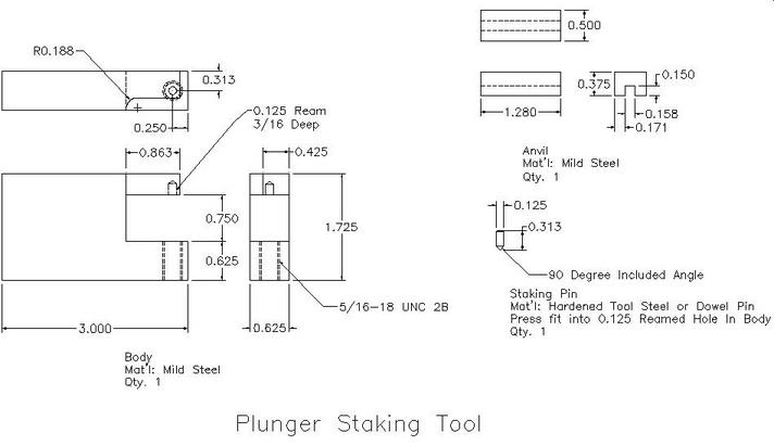
Finally, the two tools in the bottom center are used to stake the plunger tube in place. The large tool is the actual staking tool and the small slotted tool prevents the plunger tube from being crushed as pressure is applied with the socket head screw.
I realize that most people don't have access to a full machine shop and have to buy a lot of their tools but if they can make just one simple tool to make their life easier and save some money, it is very satisfiying.
quote:
Below the lug iron and to the left is a fixture to measure the distance from
the breech face to the locking lugs.
That's the one I'm curious about. Can't tell from the photo, but... Is it radiused to match the slide's lug slots? A corner may give you a false reading there. I like it. I'd like to see the blueprints on it.
I made my own lug gauging fixture years ago out of round stock, a spring, and a set screw. Simple and worked like a charm. I loaned it out and never got it back... so it looks like I'll be on the lathe soon. I made a makeshift set from 3 old barrels, with 2 different lugs ground off of each... and feeler gauges between the hood and breechface gets me to within a thousandth inch of true location. From there, it's a matter of file and check to wiggle the barrel in with layout fluid to show me when I've picked up another lug.
Again... Good work! All you need now is a set of frame rail swaging punches and ground way bars in .001 increments and you're good to go.
Tip:
The safe sided lug file that you made? Brownells sells a square pillar file with two safe sides that fits between the slots perfectly... for 20 bucks. It's listed as a hammer squaring file and leaves a nice finish.
I had originally intended to round the corners but I didn't. This is why I wanted the resident experts to look at the drawings before I post them. Out of curiosity, could you explain how could it cause a false reading? I guess it could if the face of the slide lugs weren't uniformly machined from top to bottom, but then you would have bigger problems than a false reading. I originally got the idea from Volume 2 of Kuhnhausen where he shows a similar fixture on page 128 with square corners. (I guess even Kuhnhausen can make a mistake.)
I also have a hood filing/stoning fixture on the drawing board but it is still in the VERY early stages of design.
I think you're referring to to drawing #2 in the book. That's a barrel alignment block. #1 is the lug finder. I made three similar gauges... one to check each lug. I like your idea though, and want to look at it a little closer.
You'll notice that Kuhnhausen's barrel-based tool only gauges the first lug.
Can you spot the flaw in that line of thought?
Clew:
There are three lugs and three slots... with tolerances on all three... in
the slide and on the barrel.
You'll look at it for a while, and then it'll hit like a bolt from the blue.
In my book, drawing #2 is called a Lug-breech reference fixture. The barrel alignment block is drawing #3. Just reading the notes on the bottom of the page, my fixture and the fixture made from an old barrel does the same thing except with mine you don't have to have 3 separate fixtures. You can kill 3 birds (lugs) with one stone. I will try to post a better picture of it tonight.
Okay... I see it now. I use Kuhnhausen's little book for dimensional references, and haven't really paid much attention to anything else.
Lookin' close... it still looks like he's made a fixture to gauge the first lug only. I think yours is a better one... IMHO.
Figured out what's wrong with the approach of fitting only to the first lug yet?
Quote:
Er... fitting only the first ignores the other two lugs? With only one lug
engaging well, you've got a half-done fitting job that won't be as accurate as
it could be.
Close... but that's only one concern when gauging only the first lug for a fit.
If the vertical engagement depth is 95-100%, the first lug will do... for accuracy and strength... as long as standard pressure .45 ACP ammo is used for most of the shootin'.
Clew:
Fit required barrels come with an overlength hood to allow the smith to
ease the barrel in with zero horizontal play. This method assumes too much.
As far as the lug fitting question goes, before file touches metal you need to check the relative spacing of the barrel lugs to see if they match the slide lug spacing. If they don't, then you have to get that right before filing the hood to length. That is the reason I built the fixture. Tuner gives an excellent explanation of this in one of his barrel fitting posts and is a now a sticky.
3jaw...Kudos!
The problem with the overlength hood/file to fit method is twofold.
First, it ignores the other two lugs on the 50/50 chance that filing the hood to a close fit will engage more than one.
And... the main problem is that in ignoring the other two... it assumes that the strongest, most supported lug... #1... will bear the brunt of the recoil forces when the gun is fired.
If the locations of the slide lugs are within spec... on all three... the chances increase, but there is still no guarantee that either the 2nd or 3rd lug won't be the ones to take the hit. The cause is one that all machinists and toolmakers are well-aquainted with... Tolerance stacking. Since it's a fact that there's no such thing as a perfect dimension, and all dimensions have an allowable variation... sometimes those variations can stack in the wrong direction.
Take the three lugs in question. They ALL have an allowable variation as to their on-center locations AND their geometric dimensions. This is present on the barrel and in the slide. If say... the #2 on-center location in the slide is .003 inch further rearward than nominal... and the rear wall of that lug is .003 inch overwidth... and the mating barrel lug also has those variations in the opposite direction... AND lugs 1 and 3 are at nominal spec... you're guaranteed that the #2 lug will be the only one bearing the recoil forces when the lugs engage under pressure when you simply file the hood to a tight fit within the slide. Lugs 1 and 3 will be kissing air.
This is my normal caveat with the Kart Easy-Fit system and other similar methods. While the gun will likely perform quite well with that type of fit... its useful life will be greatly reduced.
Why? The lug faces deform a tiny bit with each round fired... barrel faces set back and slide faces set forward. With each .001 inch of deformation, headspace increases by a like amount... and it increases in the dangerous direction... because as the lugs deform and increase the headspace in this fashion, the breech opens by the amount of increase. The cartridge backs out of the chamber until the slide stops it... and if it gets to the point that the case head becomes too unsupported... it blows.
If your barrel fit provides a .908 static headspace dimension... and the unsupported lug sets back that .012 inch as described above before it picks up another lug... you're at the maximum allowable static headspace dimension. Another .001 inch, and the gun is unserviceable according to ordnance specs.
Also... with .012 (only .003 inch shy of a 64th inch) the barrel now has that amount of vertical movement within the slide... which means that each time the gun is fired, the lugs take a running start at each other... accelerating deformation and starting the process on the other lug that came into play.
This is known as "Slap-Seating" and is destructive. Two pieces of steel that impact deform faster than two pieces that are pressed together... even with the same peak force.
So... The issue stands: How do you know what kind of fit you have if you don't gauge the lugs to see where they are? Answer: You don't. A wise pistolsmith made a remark: (Can't remember who it was... but it may have been Ned Christiansen) "I only know what I can measure."
There endeth the lesson.
Finally, a couple of drawings
Sorry this took so long, but here are a couple of drawings. One is the sear jig and the other is the plunger staking tool. The plunger staking tool requires a 3/8-16 bolt that is flattened at the end of the threads. The sear jig requires an 8-32 socket head cap screw that is long enough to reach the sear. Look them over and see if I have made any mistakes or left out any dimensions.