
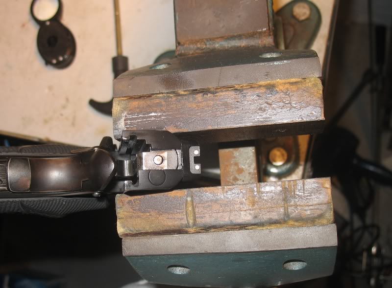
This may be old news for some, but I figgered this one out today while fitting an EGW firing pin stop.
I was slowly filing here and there to get the stop all the way up into the slide. I kept installing the firing pin and spring to see how I was doing. When I got close, the firing pin entered the firing pin stops hole, but not all the way and it was tight.
How do I know which way to go?
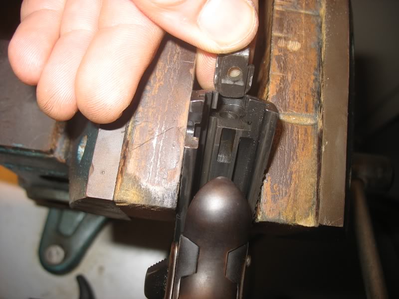
I took the spring off the firing pin, put it back in the firing pin channel and pointed the slide up, allowing the firing pin to fall back toward the FPS by gravity. Looking up, I was able to see exactly which way the FPS needed to go as the spring wasn't forcing the pin into the hole.
A few more swipes with the file and the firing pin fell right into the hole under gravity alone. I have to admit I was pretty pleased with myself. Hopefully this can help someone.
I thought that aftermarket firing pin stops are oversized (wide) with to the right side of the hole meaning that you should only remove material from the right side while fitting. This helps with extractor fitting too. Others may chime in and correct me if I'm wrong. I peen the right side with a punch to tighten it up if I made it too loose while fitting.
I needed to remove material from both sides of the EGW stop I just did, but I did take more from the right. That was on a Caspian slide. I fit two others, both on Springfields, and I'm pretty sure in those cases I only took material off the right side as you say.
I used to fret over getting the proper radius on the EGW FPS. Then, after 3,000 rounds in my 1927 Colt-Hartford Duty Pistol, I discovered that the hammer will make a radius of its own choosing. Now, I just 'break' the edge and let the hammer go to work.
I use a method similar to yours to get the FPS all the way up into the slide.
Tom -good idea- I filed a little off the right side and had to sand (glued to a block of wood) the back side of the FPS to get it to slide in on my 1941 Brazilian Colt slide. My original FPS (can't remember make) only needed a little filing on right side edge. Still sounds like a good tidbit to remember though.
I was under the impression that material should be removed equally from right and left sides to properly fit the FPS and keep it in alignment with the firing pin. Maybe John, Tuner, Niemi or George Smith can give us a definitive answer.
I removed material equally from both sides when I fit the FPS to my Springfield. Or at least I tried to.
Before letting the new FPS even see a file, it would be nice to know how well centered the slide's FP tunnel was. Knowing that (and a few other measurements) would give a plan of attack before picking up a file. Measuring the width of the FPS slot in the slide is easy, but...
...anybody ever figure out a way to measure the FP tunnel's position in the slot?
Quote:
...anybody ever figure out a way to measure the FP tunnel's position in the
slot?
The appropriate size drill rod in the F.P. tunnel and use calipers to measure from the drill rod to the inside cut on the slide on both sides?
The width of the FPS does not control the location of the firing pin hole.
Otherwise there is no need for the raised face if the width control location. A plate would be easier to make too.
Hi WyoBob: The ID nibs of my Mitutoyo's won't go up in there far enough. Maybe other brands of calipers will.
Hi Egumpher: What I was wanting to measure was the actual location FP hole (tunnel) in the slide more than anything. It's supposed to be dead-center in the slot for the FPS, but in this day of modern manufacturing technology - who knows where it really is?
-------------
I suppose if a FPS ended up getting fitted for width and the FP wouldn't come back through the hole in the FPS, the hole in the FPS could just be elongated so it would.
Here are the stackups and fits and clearances:
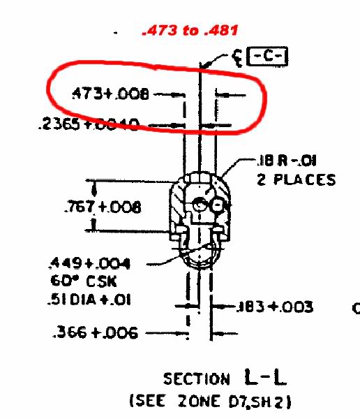

According to these prints:
overall width of FPS: .465 to .467
Slide cut: .473 to .481
This makes a .006 to .016 loose fit for the overall width
With of the raised face: .310 to .313
Slide cut: .315 to .320
This makes a .002 to .010 loose fit with the raised face.
There is a small likelihood that the .006 to .010 tight to loose fits would give control to the FPS overall width but I don't think this is the intent of the design.
Dang, you're good with those blueprints!
But those blueprints just tell where & how big things should be. What I'd like to know is where the back end of the FP tunnel actually is in relation to the sides of the slot for the FPS - and where it actually is on the slide in my hand.
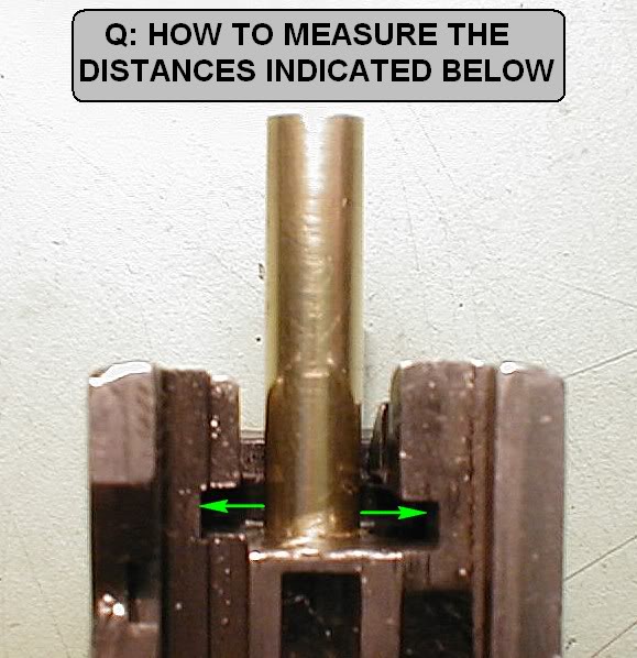
For instance, the average slot's 0.477" wide and the average FP tunnel's 0.221" dia.. So if the tunnel was centered in the slot there's be (0.477 - 0.221) / 2 = 0.128" from the hole edges to the slot walls. It's those (supposedly) 0.128" distances I'd like to figure out how to measure. If they're not equal that indicates the back end of the FP tunnel is not centered in the slot from side to side.
And if the tunnel's off center, the FPS needs to be trimmed so its hole's off center by the same amount and so the tunnel aligns with hole in the FPS. In other words I'll know where & how much to file the new FPS for a (supposedly) perfect fit before I even start filing.
Small holes are best measured by gauge rods. Expensive - but a set of well sized drill bits, also a bit pricey, work well when selected by feel and mic'd.
Enco has a set of gage plugs on sale now for $32.95 from 0.061" to .250" (190 pcs). Should cover most pistol work.
Thanks for the leads on the pin gauges & drill rod, but (as my words seem to have failed me) here's a pic of my question:
I'm starting to think there's only two ways to get those distances:
* File a piece of flat stock to just fit and then measure the flat stock, or
* Subtract the distance from the slide's flat side to the slot from the distance from the brass tubing to the slide's flat side.
None of my measuring instruments will fit in there to get a direct measurement.
Cast with Cerrosafe and measure?
Good idea!
Now to figure out how to keep the casting from getting stuck on the extractor. Hmm-m-m.
Its been a while but I found my tooling/fixturing hat and put it on for a while.
Some shim stock and pin gages will measure that.

Please be informed that I am holding you personally responsible for the addition of a pin gauge set to my "wish list"!
To see how well the tunnel was centered in the FPS slot, I finally decided to just make some indirect measurements, do a little arithmetic and calculate those distances. Then I could mentally practice Tom's fine technique. After finding the tunnel in this slide was almost 0.005" to the right of the slot center (C1 was 0.009 more than C2, below)...

...I grabbed my last NIB EGW FPS to see if it was wide enough to get the holes to line up. My first width measurement was a bit casual and told me it was 0.490" wide. As the slot in the slide measured 0.479" wide, 0.011" narrower, I jauntily proclaimed "Plenty of extra width to get the holes aligned good". [nyuk-nyuk!]
Then I decided to see if the hole in the FPS was centered. Took some measurements and added them to see if they equalled the 0.490" width. Way off. Dang! Hmm-m-m. Looking closer at the FPS I spotted some sizeable burrs or flashing as shown above, circled. Re-measured the width, but above the burrs, and things added up OK - the hole was centered nicely.
Discounting the burrs/flashing, the FPS was only 0.003" wider than its slot in the slide and not wide enough to get the holes aligned perfectly. But, if the burrs are used as part of the width it could be done, but might not stay tight too long - not much metal in the burrs.
Anyhow, not knowing how common it is for these FPS's to have burs, it might pay to look for them and, if present, take them into consideration in your fitting/filing plan.
Tom: thanks for opportunity to discover that. Too long since fitting the last one to remember if it even came up.
Quote:
My catalogs show sets with either plus tolerances or minus tolerances
I choose the + tolerance because I will order replacement pins for the pistol based on the pin measurement. The + pin guarantees that the replacement pin will fit in the hole because the measurement was to the large side.
Excellent explanation. Must be excellent if I understand it on the first reading.
Dang... Wish I'd a thought along those lines before I bought the minus set.
That said I find them useful to gauge holes and measure things, subtracting half the pin diameter and using the outside of the pin.
Numbered drill bits make great plug gauges.
That +/- thing with gage tolerances is a funny thing. I've accumulated a small assortment of ring gages, each one with what (for them) is called a "master tolerance" meaning the nominal value is in the center of the tolerance band instead of at the top or bottom of the tolerance band. Got them that way on purpose to serve as reference standards for calibrating caliper ID nibs, etc.
Anyway what's funny is - never saw pin gages with a master (centered) tolerance. Just + or -. No +/-. Maybe the reason is lack of need for such a thing. For calibrating outside micrometers & calipers I just use gage blocks - and their tolerances are the +/- type.
Did I just explain away my puzzlement or further confuse myself?
Quote:
Numbered drill bits make great plug gauges.
And an inexpensive way to (sort of) get the in between sizes is to use taper pins, if you can find the smoothly finished ones.
In the old days holes were toleranced with a + X -0 because you can alway make a hole larger and tool wear would cause the hole size to grow. Likewise a pin was toleranced with a +0 -X tolerance because you can always make a pin smaller and to account for tool wear too.
A gage set should guarantee a minimum or maximum measurement hence the single sided tolerance and why I choose a plus tolerance to guarantee a minimum hole size that a purchase pin would fit. If the tolerance went the other way I may get a hole size that is actually smaller that the pin I bought.
A gage should guarantee that the mating part will fit.
Edit: I would like to add that if the holes to be measured are for interference fit pins like axles or bearing races then you would want to use the minus gage to guarantee that the holes are no larger than what you measured with the pin or the interface may become too loose.