I going to take on my first 1911 build and picked up a frame from KT (as I gave up on the idea of building an AR10 due to increased parts costs and lack of availability to my liking). They sure look nice to me, but I'm not clear on what needs to be done for what is described as "the barrel seat cut". I have a general idea of what needs to be done, but if it could be spelled out Slo-ly I would greatly appreciate it. Pictures and/or diagrams would help me out even more.
Thankfully the "slide rail cuts, hammer and sear holes, and parts fitting" portion of the build are easy enough to understand. But, it's this darn barrel seat cut that leaves me second guessing myself.
The normal cutter diameter is 0.700, anything between 0.700 to .750 will gitter done. I've used a .750 ball endmill to chase the channel after a frame ramp reweld.
Basically mount the frame to have slide rails prefectly vertical (parallel to the cutter). Then, with your endmill (be it .7, .75, .8 being the specified diameter) simply "drill," with the quill, a small groove for the barrel to go down into when it disengages the locking lugs on the slide.
Do this "drilling" of very small amounts of metal, then move the table over (into the cutter :p) Until it is to the specified depth. With a .75 cutter, my idea depth was .065" or so. With a .8 cutter, it is supposed to be .06.
Depending upon which set of blue prints you use... I found it in this one, which was WAY better than the one you get on the internet by John Browning. That set is for the 70 series and isn't quite a working drawing, but it does have some of the basic and necessary dimmensions.
It's .060 one. Kind of hidden in the mess of it all. Let me know if that helps.
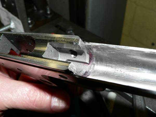
Thanks - that would be perfect if I could also see what it looked like from the top. I appreciate all you guys input.
This is mine from the top. I used a 3/4" ball end mill.