Retrieved: January 10, 2011
Last Post: August 21, 2003
I'm still waiting on my Tannery 80% frames so I decided to work on my 40% frame I have sitting around for the time being.
First off, if you don't have a blueprint get one. Then, with dial calipers, micrometer, etc, in close proximity, measure this thing to see what is and isn't in spec for the frame.
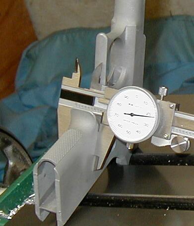
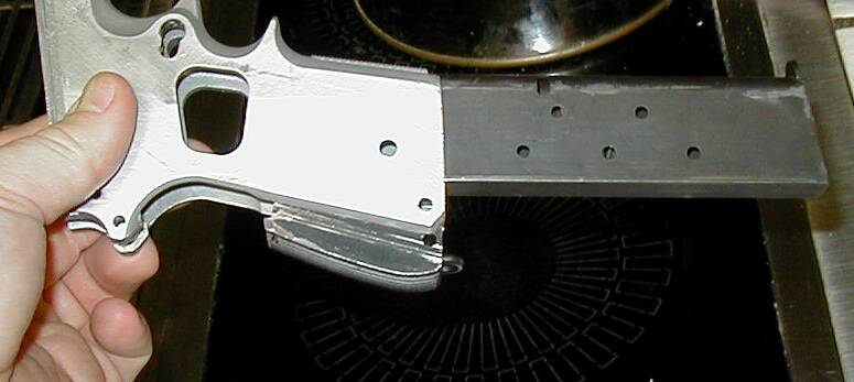
For the Aluminum 40% I have the frame was .840 wide. The blueprint calls for .750 wide, so it will need to be narrowed a bit. The trigger guard was the correct width already, so no fixing there. the height from the mag release hole to the top of the frame is listed at 1.538, and on my frame was 1.645. That will need to be milled down as well.
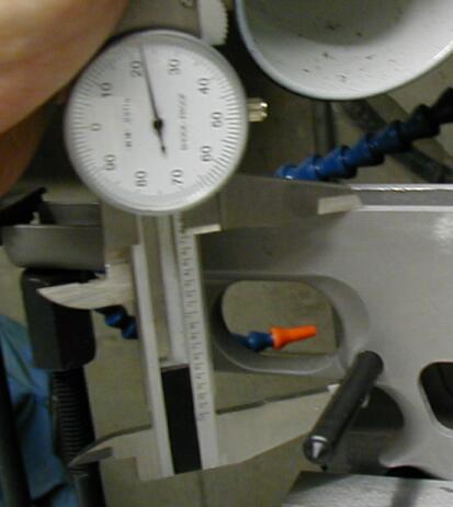
That's how I measured to the top of the frame. If you measure this way don't forget to subtract half the width of the pin in the hole.
Once you've measured it out and know what you'll have to cut, get to the hard part of machining, setup. Clamping an aluminum frame tightly in a big milling vise is going to bend it, so we'll have to work on something to hold it in place without doing that. I machined a small chunk of aluminum the width of the inside of the mag well and inserted that in the frame before clamping it. A magazine wouldn't have been sufficient, since there is a bit of play and the sheet steel would have provided little support. (sorry, no pic on that one I forgot)
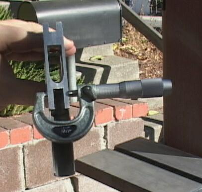
First I decided to mill the top edge flat, since this is where you measure everything off of. I don't have a machinist's level yet, I'm broke so I used field expedient leveling tool:
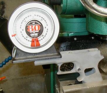
Not the most accurate, but fairly close (yes, I measured the table to see if it was level, and it is).
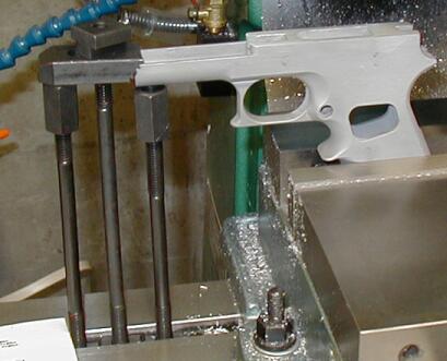
In addition to clamping the frame in the vise, there's a fair amount of material that is overhanging and needs to be held in place so the frame doesn't slip in the vise.
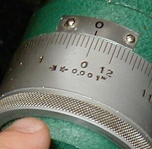
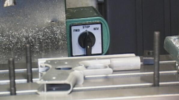
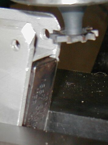
Re-verify level after clamping to make sure you didn't move it while tightening everything. Now, I only have a 1/2" end mill, so I'll have to make a couple of passes over the top, taking off .015 each time (I'm conservative, ya know...) till I'm close. I like to remeasure after each pass, to make sure i'm cutting the right amount. After touching off, make sure to zero out the dials on your mill if you have these type:
Ok, now let's mill this bad boy. I don't have power feed, so I have to crank by hand. I managed to crank a blister on to a finger doing this too.
And once it's cut down to size:
Once that's done, next you'll have to make the frame a little thinner. Since this is aluminum, I'm going to use a fly cutter and cut it down. Might take a while, though. Otherwise it's a lot longer using a 1/2" end mill... no thanks
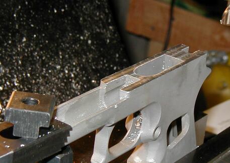
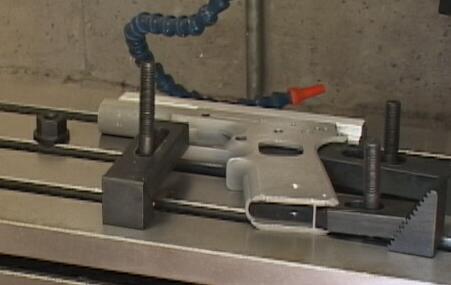
I'll have to get a pic of the clamping that I did to hold it down, sorry. In any case, first I passed both sides across the belt sander to get any high spots out. Then, using the mainspring cut, the top of the magwell, and part of the dust cover, along with the trigger guard, I clamped the frame down.
Once you've gotten one side cut, flip it over (make sure to clean out any particles on the table or frame so it lays flat). mill the other side as well.
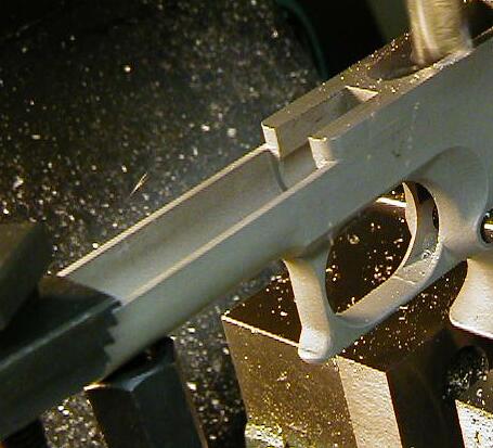
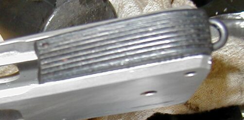
Here's where I am now:
I still need to take off a couple thousandths from each side. I'm waiting to do that after I mark and drill the rest of the holes in the frame.
Oh yeah here's what I've found out while doing this. When you are cutting, spray some WD-40 on your cutter and part before cutting as it helps the finish a good deal, as well as keeping chips from sticking too badly. Helps keep the cutting a bit quieter as well.
For Fly cutting, I take small passes. Sure, it's going to take a while to cut .045 off in .005 passes with a 2" cutter, but imagine how long it would take on a belt sander. If I had a larger endmill (say, 1" or at least 3/4") I'd probably rather use that. I kept all the x & y axis unlocked while doing this, and locked the head. Go slow and don't rush. you can take more material off if you want, but since I've never done this before I'm chicken. :D For the last two passes I'll probably take .001 or so per pass.
Clamping setups are a pain. If you are fly cutting, then you have to make sure that the clamps are out of the way, or under the level of the fly cutter. I milled a bar of 1" aluminum to fit one of my t-slots. It's about 4" long and works well for some setups if I need a flat surface to be firmed against. The 1911 frame has lots of places to clamp onto. The mag well on both ends, the mainspring area, and the dust cover if you're careful. The trigger guard is also available, since the front/underside of the frame doesn't have many spots to clamp. I used my AL bar to hold that side in place, and then clamped the trigger guard as well. This was sufficient for my needs, but may not work well on heavier cutting.
Sharp tools cut much easier than dull ones. Check your endmills and cutters for chips between cuts. Especially with aluminum, this can be a problem.
Ociebell reminded me that I forgot his question. In response, no, the magwell is a single contiguous piece, and there does not appear to be a void under the finger groove.
On with the show....
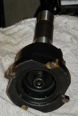
I mentioned that I'd cut a bar to fit the T-slots on my table and use that as part of my clamping. Here's how I set up my fly cutting:
Someone asked about the flycutter:
Tonight's mission was to layout and drill some holes. First collect all your measuring and layout tools you will need...
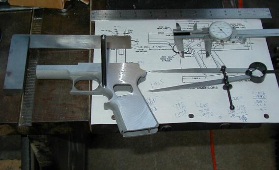
Dial calipers, square, transferpunch (used to help measure from the mag release hole), dividers, ruler/straightedge, scribe (hidding off camera), and blueprints.
First I did the takedwon/slide release hole, since most other holes are referenced from it.
I gently tapped a decent sized hole with my transfer punch so as to make it easier to line up for drilling. Don't beat on it too hard if you have an Aluminum frame, of course. Aluminum drills very easily. I used some more wd- 40, and a drill bit one size under whatever the hole is supposed to be reamed for. Then i'd come back and crank the right size bit by hand through the hole to pseudo-ream it. This makes a very tight fit, although not reamed to exacting size, it's pretty close.
The doohickey that attaches to the frame between the safety and takedown lever has two holes, both along the horizontal axis of the frame. If you lay the first one out and are comfortable with how accurate your mills dials are, you can just crank .801 after the first hole and then drill the second. Of course, your table and the frame need to be moving parallel to the axis of the frame, so make sure you're all aligned before trying this.
Remember if you are doubting your measurements, go back and start them over. This finally bit me, as I was laying out the safety hole. Of course, I did measure twice, and both times, I neglected to add the .100" for half the diameter of the punch in the hole as I measured the distance. This put the hole .100" too short. Fortunantely I only drilled one side for this hole.
For now I'll finish the rest of the holes on the frame and then decide if I can fix it reliably. I'll finish narrowing the frame and cut the rails as well. So, if you have any suggestions on repairing a hole in aluminum, let me know!
Lastly, this is being slated for a 22 conversion on the top end, if it works when I'm through farking it up. So it's not expected to see heavy duty use by any stretch of the imagination.
Instead, I just mounted the frame on my mill and did the layout with it:
This worked quite a bit better, and I finished it in about 10 minutes.
For the holes, I found my drill chuck has more runout than i'd like, so I used a step down on the drill sizes in order to make the holes just a touch undersized.
I didn't fill the hole I mis-drilled yet, but here's a pic of the left side, then one with a highlight of the mistaken drill.
Ok, now I need to thread the grip holes, ream a couple more to size, cut the mainspring cut, then flatten it a bit more and cut the rails. And after that hopefully I'll have a working gun.
The first print I was working off was definantely wrong. I forget who I had to message (bybon, I think) one night to see if it was correct or not. The second print (both from the library, btw) was the picture file. Some of the numbers were a bit hard to read. I managed to get most of them, but the hole I farked up was my fault, not the print's fault....I think that's talked about on page 1.
The latest PDF print in the library seems to be the best one to work off of (and the one I used to do the majority of layout). I'll have to dig up my prints from tannery and compare them against it.
The current holes are "correct" from the takedown/slide release hole. I decided against goofing it up with my layout tooling and just mounted a punch in the mill and went to work.
My mill has .001" graduations on the dials (which are .001, or really really close). This made it pretty simple to count out 1.938" (or whatever) fairly accurately. Zero in the middle of the takedown hole, and then move from that position to the rest of them.
I used one or two size smaller drill bits to keep the holes just undersized. the drill chuck I have has a bit of runout and I didn't want to supersize my holes before I'd even gotten to assemble the thing. I will have to ream the holes. I don't have any reamers, I might use drill bits after all. we'll see.
I haven't learned to weld (yet) nor does anyone close to me have a welder (that I know of), so I am debating one of two things, either JBWeld (or something similar) or trying to turn a small aluminum bar to size and pressing it into place. I can peen the hole with a punch (and the turned piece) and then use some J B Weld on it when I put it in, and that would probably work as well. Any comments?
This frame is my "tester" in the respect that I have an 80% frame coming, but I wanted to try and make this one first, for the experience. So if I screw it up, well, hey...I'll live. I can always get another one, 40%'ers seem to be in stock more often anyway.
One of my buds who's a former machinist razzed my fly cutting job until I mentioned I'd never done it before and was sort of guessing on some parts of it. Then he said it was "ok" for a first one. He said I should have sped up the cutter and slowed down the feed. I think I'll have to get one of the KT B52 fly cutters if I do anymore of the 40%'ers, though, so I have a decent cutter instead of the one included with my mill.
If I were to do this again, I wouldn't narrow the frame until after I'd layedout and drilled all the holes. Second, I did a minor oops by not mounting the frame up on something so I could drill through it when I did drill most of the holes, cuz it was flat on the mill table...not something I want to drill into. Instead, I drilled the bit just past the angled tip so the edge was into the far (bottom) side of the frame. Then, once I unclamped the frame, I drilled through after mounting the frame on some parallels. Ugh. One plunge per hole is enough!!
I'm still not sure about cutting the mainspring housing slot yet, I'll figure something out, i'm sure.
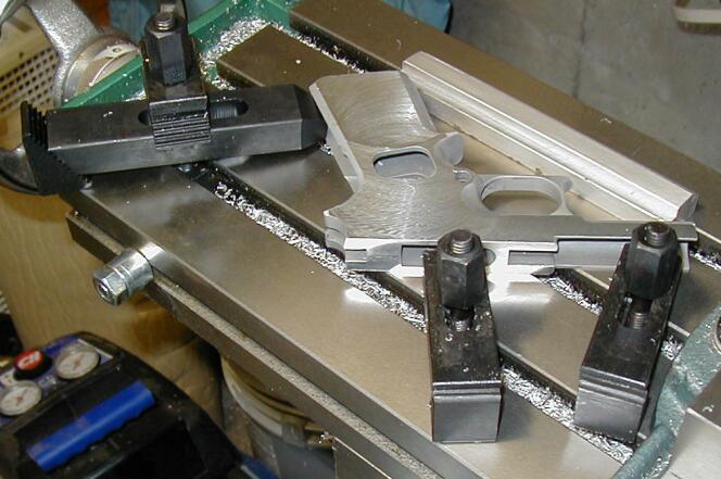
If you're just joining this thread, I milled a 1" bar of aluminum to fit the T-slots on my table, which is what you see at the rear of the 40% frame.
Here's the basic layout I'll use. The three studs are in the rough positions i'll be using to hold the frame in place. I clamp the frame on the trigger guard, the low end of the mainspring area, and in the grip safety area.
That's the other side I've got hooked up, but you can see where it's going. the bar that is on the trigger guard needs to be adjusted a bit from where it is right now, though.
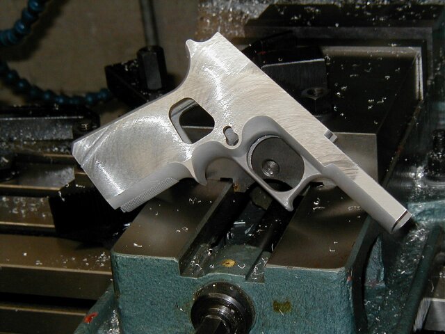
Once I finished milling the sides down, I sanded it with 320 on my belt sander to get it even closer.
Also... if you are doing a 40% and the sear pin hole is troublesome (cuz it's hitting just about on the angled face of the interior), drill it the tiniest bit into the opposite edge, then, stop, lower the table, get a transfer punch, and tap the opposite edge a few times to make a good imprint for the drill to seat in without deflecting. This doesn't work so well on steel frames, btw. My handy new Oops I learned something new for the day.
First, I did the msh slot. This wasn't as bad as I thought it was going to be, except for one thing. The keyway cutters I have were all a bit too big. Since I have a couple of each of them, though, I decided to make one fit. so I chucked it in the mill, spun it, and used a medium stone to shave about .015 off of the face of the cutter.
If you do this make sure to clean up really well, since that size of particle can get into everything and scratch and muss all sorts of stuff.
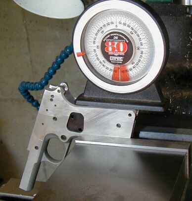
Anyway, onto the msh slot. First, I mounted the frame in my vise, which I had to reindicate, as I moved it again. My handy little anglemeter works pretty well. not quite as accurate, but it reads up to 1/2 degrees, so you can be pretty darn close.
Then was the fun of marking the part. The blueprint I was working off of only had the length, not the width or depth of the cut. I measured the width of the rails on the mainspring housing with my Micrometer, and used that number to make my cutter the right size. Then, I measured the width of the mainspring housing itself, and then with the msh and the rails. Take the difference between the two and divide it in half, and that's roughly how deep the each slot has to be. I lucked out that my cutter was about .004 narrower than the overall size of the msh and rails. So I ended up cheating a bit :)
Now, once I've gotten those measurements, I had to mark the correct spot to start cutting. I checked the distance between the furthest edge of one rail and the center of the pin hole (at the heel of the MSH). I stuck a transfer punch through the hole and then using my micrometer again, checked that measurement. In order to get the cutter positioned right, I stuck the transfer punch in the frame. Then, with the cutter in the mill, I moved it down to where it the top of the cutter just touched the bottom of the transfer punch. I moved the table a bit and cranked it up the distance I measured on the part. This should make the cut at almost exactly the same height as I measure on the part itself. (yep, this is confusing and I forgot to take pics during it, sorry)
Ok. Now we're ready to cut. Per another thread, I'm going to go slow and cut at about 650 rpm. I almost emptied my small wd-40 bottle, I need to buy this stuff in gallons :) On the blue print, the cut is listed as 1.830 long. This is from the center of the pin hole, though, not the bottom of the frame. The center of the pin hole is .138 from the bottom of the frame. So I'm going to cut it 1.970". The slot is going to be angled in a bit at the far end, since the cutter is round. that's included in the measurement, it appears. I centered the cutter between the edges of the frame.
When you are cutting, take note of which way the cutter turns. This is especially important if, like me, your cutter is wider than the internal area of the frame. However, it's not the exact width, so I'm going to have the cutter more towards the near edge of the frame (as mounted in the vice picture above) so a larger section of the teeth will be moving into the side nearest me. As I move the cutter out of the area, I'll move it towards the far side of the frame, to cut that rail to the right depth. This will put more tooth area into the far side as you move the cutter out of the frame.
So I cut the frame. I'm a bit worried about this, so I only cut the first .250. Then, I cranked the table away from the cutter enough so I could test fit the MSH. It didn't quite fit, width wise, so I moved the frame back in, and adjusted my depth measurements a tiny bit (.001" more each way). recut the first 1/4" and then it fit, with a bit of resistance. I then cut the rest of the slot.
Once it was done, I took it out of the vise (btw, test fit first if you do this). I knew the MSH wasn't going to fit exactly, but it was pretty close. I removed it, filed the edges a tiny bit, and then put it in. It goes all the way in with hand pressure, but you have to give it a good push for the last 1/2" or so.
After I finished with the MSH, I drilled the holes for the Ejector. The blueprint has the forward hole as .1250, 2.391" from the slide release hole. I mounted the frame in the vise, leveled it with my handy anglemeter. Transfer punch in the slide release hole, I touched the bit against it, then cranked the table the rest of the way down. Drilled the first hole, then, without moving the table, I swapped the drill bit for a center drill, and countersunk it per the blueprint. Move the next .585" to the rear hole, swapped drill bits, drilled, use a #1 center drill to countersink it.
As of right now here's what I can fit onto my frame:
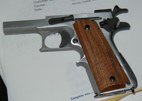
When I drilled the holes slightly undersize it was a good move, as some of the pins fit very closely right now. A couple (like the sear) are just a tiny bit undersized. So if you don't trust the runout in your drillchuck, remember to drill undersize!
it is with great sadness that I report my 40% frame is kinda screwed.
Seems that while cutting the rails, one of the supports I had for the frame came a bit loose and the rail cut is at an angle. I should have re-checked it, so it's my fault.
The rail went up towards the top edge about 12 thousandths. It's a .030 deep cut, no the whole depth. It can probably be repaired.
I had the frame mounted vertically in my vise, with clamping at the end of the dustcover. The lower support was not re-tightened after tightening the top support. hence the upward angle of cut.
After much meandering about and ignoring this project for a while, today it wasn't raining so I could go back and work on the 40% frame some more.
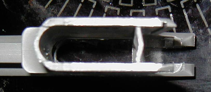
I decided to just mill out the rails and ignore the goof. In any case, the rails are done, and need just a touch of filing to be the right size.
However...
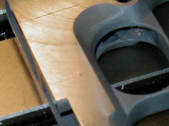
In my efforts to clamp the frame so it wouldn't move while milling, I made another problem. I used a mag in the magwell and a couple pieces of sheet metal to ensure I didn't crush the mag well. Problem is, the magazine bent. In order to insert or remove a magazine, you have to knock it out with a hammer (or clamp it with a vise).
I'll get pics up later. :( The rear of the magwell area is visibly bent. I don't see any cracks, but I suspect they are there somewhere.
Not exactly drop free huh.... (that's as far as you can shove without serious forcing)
I'm expecting a 80% 1911 to show up this week, and will probably be sending this frame back for credit if I still can. Ugh. :(
Lesson here is to make a steel shim the width of the mag well so when you do clamp it, it doesn't distort. I think if I'd used a loaded mag it might have held up a bit better as well.
Did I mention the rails look good? :) Too bad it's going to be a single shot model
The rails are just less than 1/8" wide and 1/16" deep. So don't go rush out and get a bunch of 1/8" endmills just yet. 7/64" or 3mm parts would work better, since the spec is .110 +- a couple. Using a slitting saw is probably an easier way to go. There are a couple of other sites (check out roderus custom's page) that have infon on actually cutting the rails. I'll put pics up once my mill is installed and I cut mine. Accuracy is quite critical to say the least for cutting the rails...if they aren't parallel, you will have a Super Jam-O-Matic 2K instead of a nice 1911 clone.