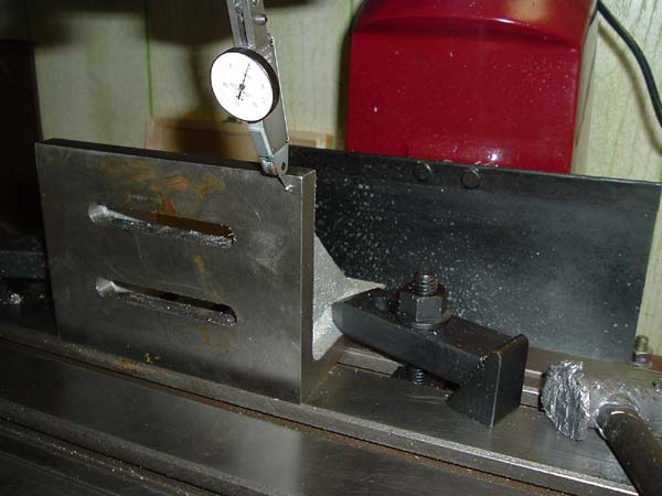
First off I decided to cut the rail slots and mill the top of the frame. To do this I set a 5" x 7" right angle plate up parallel to the X axis. Clamp the plate the table snug but not tight, set up your indicator in the spindle and zero using the y ballscrew. I bought the angle plate on ebay real cheap.
Move table back and forth to get an idea which way the plate needs to move. I tightened one side fairly tight and tapped the other side until the plate is within .0005" across. Tighten the angle plate down TIGHT and recheck.
Next I clamped the frame to the angle plate and and trued it to the x axis using a similar method to what you see above. Again I got this within .0005", but it took a little longer. Remember to stone off any burrs from the clamping face and indicated surface.
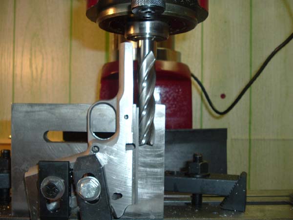
OK now I'm actually ready to start cutting, so cross your fingers. First cut will be to bring the top of the frame to blueprint spec. from the slide stop hole. First I took the correct size drill and put into the existing slide stop hole and depth miked down to it from the top of the frame. DON'T FORGET TO ADD HALF THE PIN SIZE. Subtract from the print value and that's your mill value. My frame was .015 over.
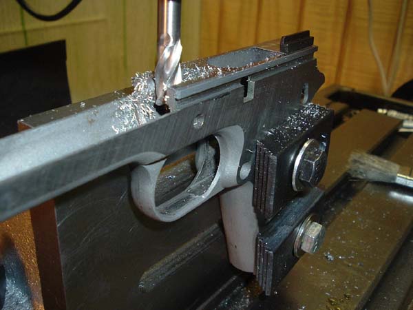
Next mill top to correct value-
I had a lot of trouble with feeds and speeds I need to find out a little more about what coolant to use with Stainless. Even with a .005" depth of cut the finish was horrible. I eventually went real slow with high rpm with some makeshift coolant and got acceptable finish.
With the top done - hopefully in the next 2 days I can get the slide rails cut.
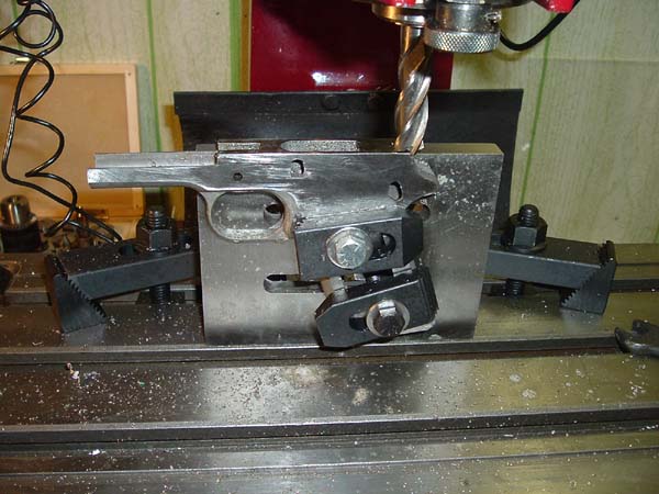
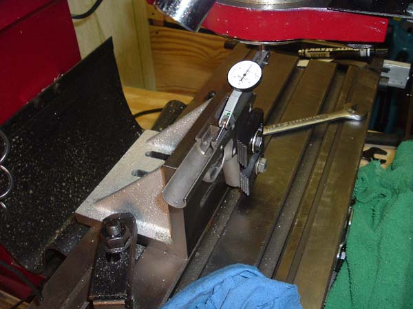
Next I milled the grooves from the same setup. Using this setup you can do both sides. I'm using a std 5/8" dia x .100? thk keyway cutter so I'll have to make to cuts to get to full width which is no big deal. I'm using about 500 rpm and .010 depth of cut. Real nice surface finish, cut great. I touched off the top for zero, blacked the side and eased up to it. Check and recheck as you go.

One side done. OK now to confess. Tighten the piss out of the keyway cutter. I didn't have it tight enough and the cutter actually pulled out of the collet and cut crooked, luckily it did it on the first pass. I TIGHTENED DOWN HARD and it cut fine. Live and learn - like I said I'm not a machinist. Otherwise both sides came out great. I machined the grooves to mean part print both sides. I next machined width with a std end mill and and left .001 on each side, checked it with the slide and it would just about start onto the frame. I took a thou of each side and the slide would go to about half way. From here its time to lap the slide in. For that tight fit ease up on it. Wait to lap slide until all vertical work is done. So far 2 hours of set-up and machining.
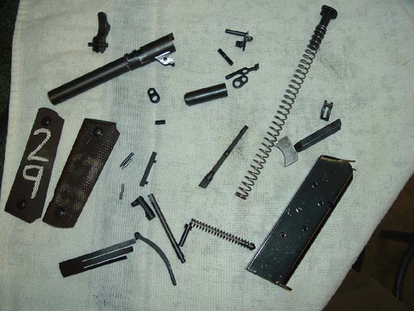
Next up is the ejector machining. I ordered a parts kit from Sarco. Hey I said I like a challenge. When the parts kit comes in I'll do the rest of the vertical work. I welcome any ideas, criticism, etc. One area I'm still looking at is the MSH cut and the main spring cut. Any thoughts for setup?
Got the Sarco parts kit today WOOHOO. Barrel looks really good all other parts look to be nice. Missing A LOT of stuff. I have to send them an email.
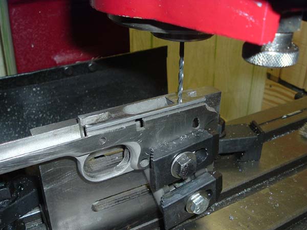
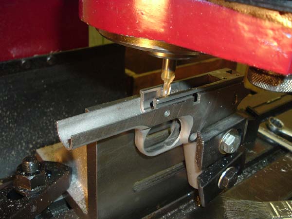
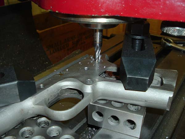
Ok next up is the ejector holes. I measured the sarco parts and selected a drill same size or next size down by a few thousandths and drilled to depth. I am using the model of the frame I imported into Solid Works and I'm cutting sections etc for the depths. I will post my print later as it my be a little clearer than the ordnance print. Picture is drilling the first hole.
Next photo is spot drilling the back hole for the ejector. I use a spot drill prior to drilling all holes just help get best location.

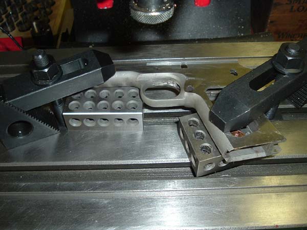
Ejector fit great with the slightest push to seat in the holes. No shake or looseness. Picture of frame with ejector installed
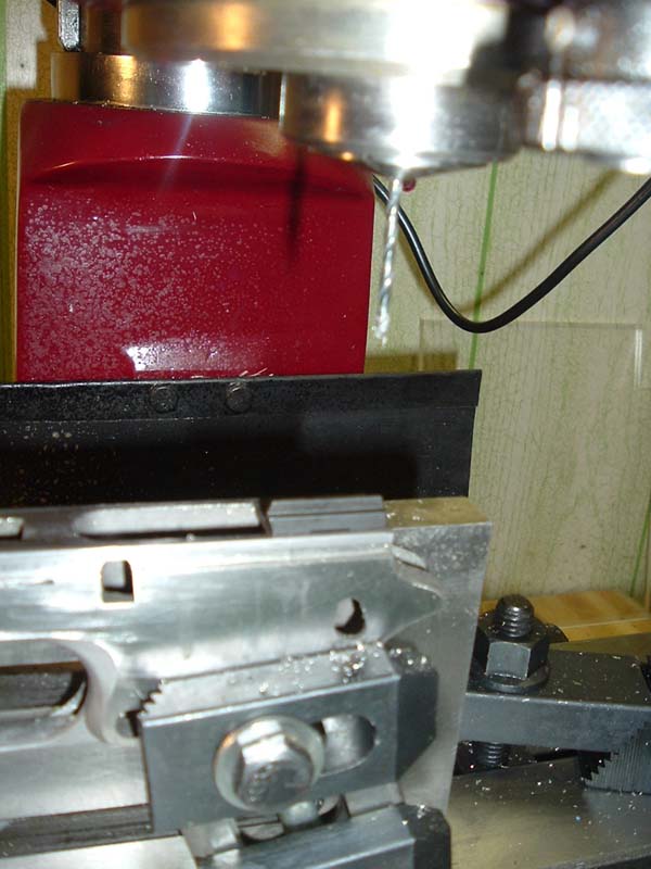
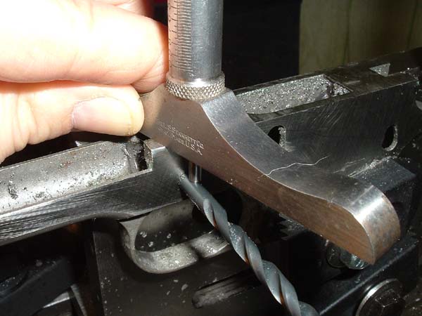
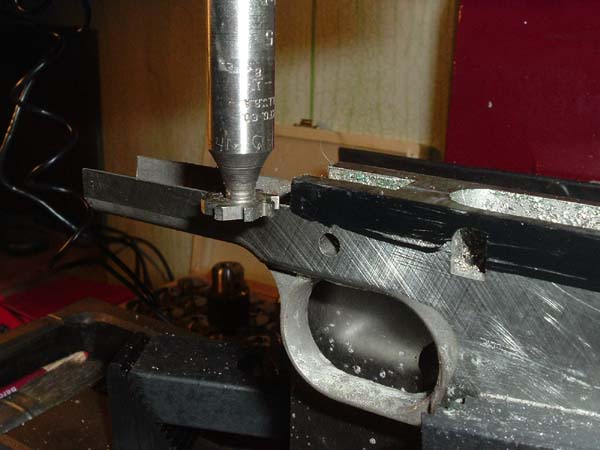
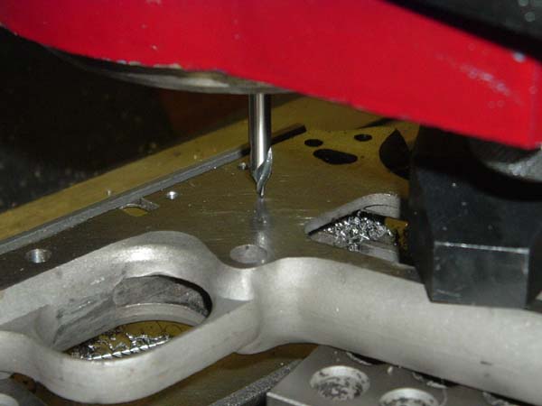
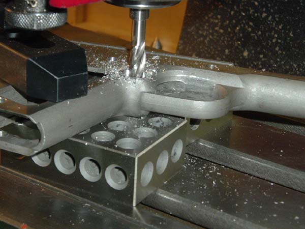
Next I noticed the slot for the barrel on the front of the frame was not up to size, so I found the center of the frame and milled to size with a 5/16 end mill. Remember to subtract and add half the actual measured size of the mill you are using. Very few of my mills are actually what it says on the mill but .010+ undersize.
I hope corner rad won't be an issue - I will know soon enough. Picture showing mill cut.
I also noticed that the rad to clear the bottom of the barrel is missing so I need to get a .700 end mill (or close) and cut clearance on top of frame. That is another setup so that will be the next step.
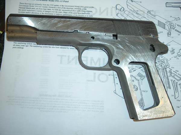
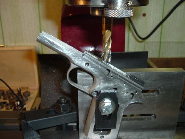
This picture shows my progress to date - wow really starting to get anxious.
A .750 end mill is OK for the barrel bed, just control the depth. You may have to turn the frame up for the barrel slot, same set up as a ramped barrel cut. Go slow or the tool will try to walk. Nice going.
I set the slide up on the angle plate and indicated in vertically within .0005" - clamped down to plate. I should note these stainless frames can take clamping this way without a filler block in the magazine well.
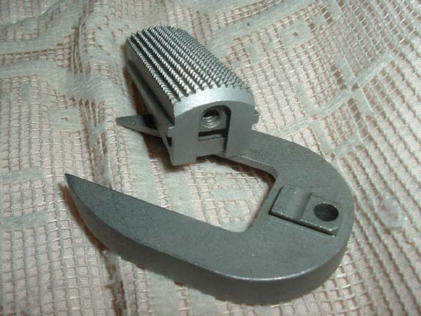
This is a "decorator" I purchased from Sarco, they were sold as is and had some dimensional problems I guess. For instance this frame is in between an officer's model and a full size government. I measured it and it is a full .245" shorter than a std length frame.
Rex B gave me an idea, I purchased a stainless officer's mosel MSH with add on magwell from fusion via ebay, I haven't received it but my thought is I may be able to use it as is or make my own add on block and fasten it to MSH.
Dogbert I would be interested in seeing your MSH and mainspring setups if you have pics of them.
xirxious I have a harbor freight, round column, geared head mill. I decided on harbor freight based on price and shipping cost. My mill only cost $75.00 to ship.
Big Art that is the Sarco builder's kit I purchased, also the speed of the keyway cutter was a gues I had no good way to do a speed. Finish was great and cutter showed no adverse effects. Since starting this project I downloaded machinist assistant and use it for speeds and feeds.

This shot shows cutter at full depth.
As luck would have it I had to go back in and clean out the corners where the barrel sits. I used the smallest mill I had which was .200 and filed the corners, barrel fits great now.
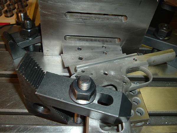
Ok time to set up for all the holes. I spent some time marking up a print to determine what holes go thru. I set the frame up on a couple of 123 blocks. You have to look at roughly where will holes go and position the blocks to clear them all. Indicate the frame using X axis travel and clamp down to blocks. Be careful clamping on dust cover not to crush it.
Ok if you frame has holes check for size and location, add all missing holes. Spot using a center drill. I drilled all holes undersize and then drill up to size. My drills tended to cut between .003 - .005 oversize. I sized all the holes to fit the pins going into them.
This frame had the tri lobe shaped machining for the safety already BUT I remachined to proper dimensions. I tried the saftey in and it fit snug but ok.
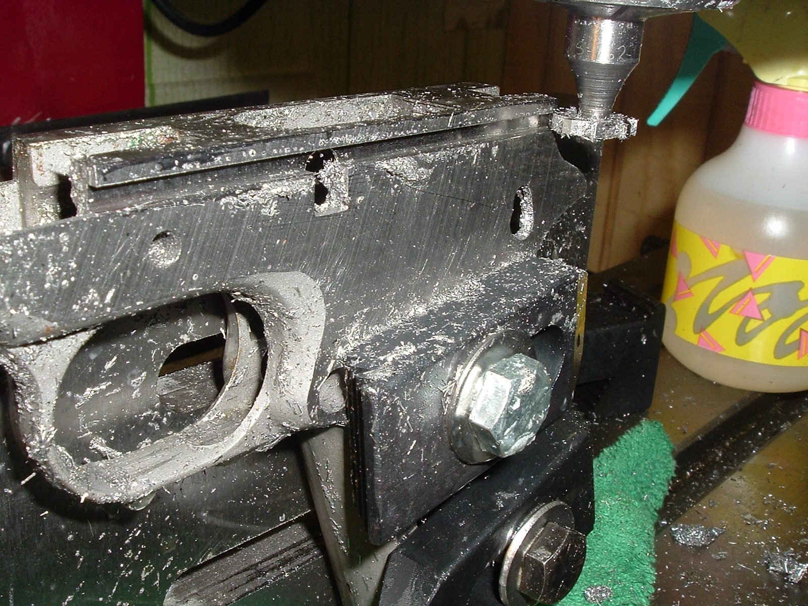
Ok now time to set up for magazine button machining. I bought some angle plates and set up the frame to the proper angle, clamped the frame down removed the angle plate. this is the setup.
I had to mill the magazine release hole to depth. now I have to figure out how to put the knotch in to hold the mag release in. Not sure what I'm going to use to cut it.
my mill is a round column geared head mill. Its still fully manual with original screws etc. I did spring for some poor mans DRO's they make all the difference in the world.
Ok this picture shows me cutting the lead or ramp into barrel, I wish I could show how I set it to the angle. The rad is .28 and it is at a 58.5 deg angle from the top rail surface. so what I did was use 31.5 deg worth of angle blocks set on the top rail surface and set it parallel to the top of the angle plate. It was a job that needed like 10 hands to hold everything. next once everything was at the proper angle and tightened up I put a drill in the barrel lock pin hole and using an edge finder found the center of the lock hole and from there it was simple matter of zeroing on the hole center line dialing over 1.0650 and plunging down with the proper endmill.
I put the slide and barrel on the frame after the cut was made, put in a clip with some rounds in it and it fed ammo into the barrel. WOW
Ok received my MSH and magazine flare I bought from Fusion on ebay. These are stainless parts and are pretty nice quality. I bought an officers model MSH but now I'm thinking I should have bought a full length. Anyway the interesting thing is the Magazine flare extension thingy is held to the MSH by a dovetail and screw. One thought I had was to make an extension that would make the frame full length but not be flared so I can use full size std grips. I'm at the point where I really have to decide which way to go. Does anyone have any other ideas or thoughts I'd love to hear them.
On another note I emailed Sarco with a list of missing parts and they PROMPTLY mailed out all the parts I was missing minus the back orders. Overall for the cost of the parts I'm very happy. Will see how happy I am after I shoot it at paper. Anyone that buys parts from them needs to have an exploded view and do a detailed part inventory or you can get screwed.
Again I really need some advise on the MSH and Mainspring cuts.
I may go so far as to model up the parts and see how they fit and where I need to add the cuts.