
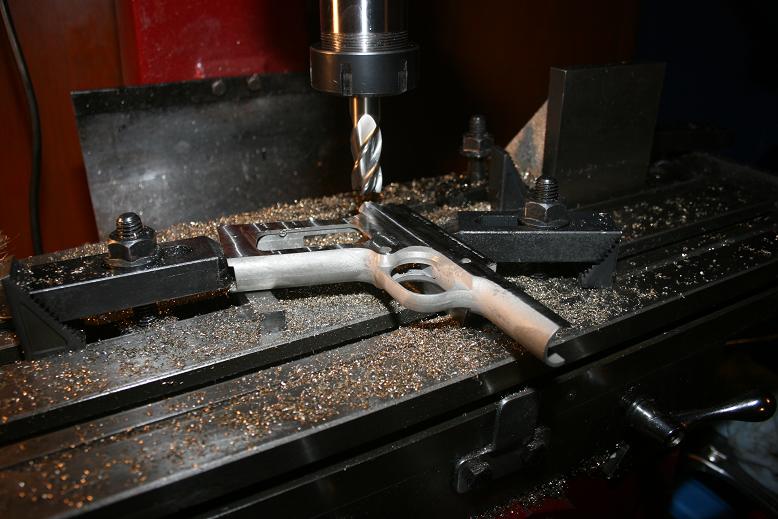
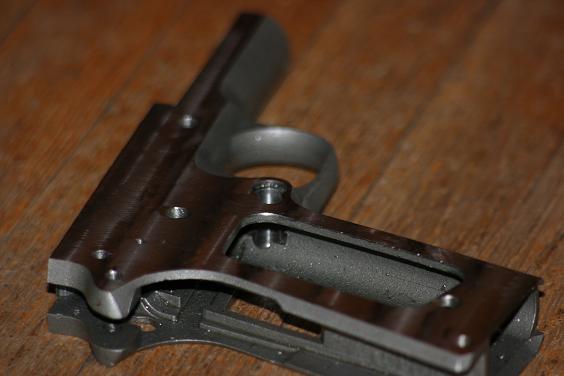
Since Sarco has frame castings for for so cheap I thought I might try to machine one and document the process here. Hopefully with this build my computer won't crash and cause me to lose all of my pictures like the taurus frame I did (I am still trying to recover them). I started by comparing the cast in features and holes on the sarco frame to the blueprints that I have. I was pleasantly surprised to find that of the 6 castings I have they are all reasonably close to spec. I measured the dust cover groove, magwell, and hammer slot from both sides to establish a center line. Once I had this established I could determine how much to remove from each side to bring the final thickness to 0.762" ( I wrote these numbers on each frame side so I would not forget).
For the first setup I clamped the frame to the deck using some ground spacers under the frame. Since this is just a slabbing operation I just eyeballed the frame square to the table. I took off 0.041" total from this side. That is all for this setup.
For the left side a little more care is in order for setup. Using the same ground blocks under the frame, I indicated the frame square to the table using the top deck surface.
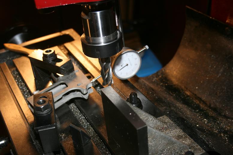
Once square I established the origin at the takedown hole (0,0). All coordinates for this setup will be based of this. This hole is bored through to 0.201". I had to loosen the fit of this hole to about 0.203" for my takedown lever to fit.
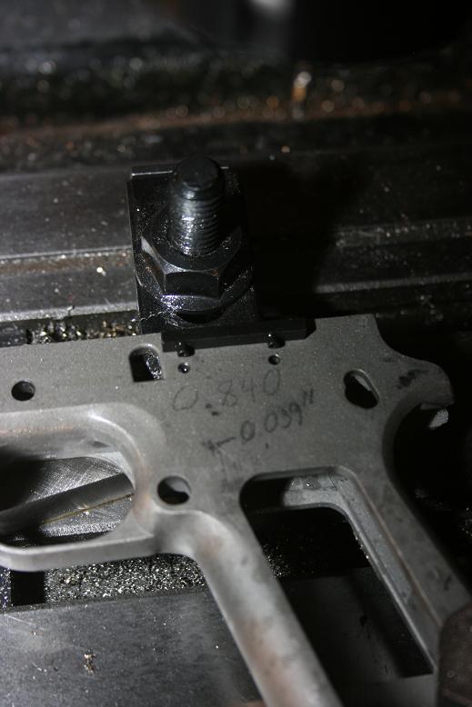
Next I center drilled the plunger tube holes (1.402", 0.76" & 2.204", 0.76") and bored them through this side only to 0.098" (#39).
The hammer (2.973",0.016") pin and grip safety pivot (3.368", -0.210") pin holes were spotted, drilled, and reamed to 5/32". Sear pivot pin hole (2.602", -0.252") was reamed to 0.110"
Grip bushing hole (1.937", -0.431") is bored to 7/32"
That is all of the holes in the upper section, so I milled what I could to bring the final thickness to 0.762"
After I started posting this thread I Thought that posting the relevant dimensions for each setup might be a good idea if anyone wants build one of these as well, but I can not edit my posts, so I will start from this post forward and see if I can get them edited (posts have been edited). Anyway, more machining.
Dimensions will be based of the origin for the setup - in this case the takedown pin hole.
I moved the clamps and finished slabbing this side - Add clamps and move one at a time to avoid disturbing your setup
The mainspring housing pin hole (3.750",-3.595") was drilled with #23 drill and reamed to 5/32" Grip bushing hole (3.018",-3.309") was bored to 7/32".
I milled the top deck surface to 0.450" above the center line of the takedown hole (0.450"). I milled the dust cover length to 2-21/32" from the center line of the takedown hole (-2.656").
Two additional operations could be performed with this setup. The hammer slot could be milled, but this requires a 3" dia. saw with a 1/2" or smaller arbor. I do not have one of these so I will mill what I can with an endmill with the frame on end and finish with a file. Also the undercut at the top of the grip safety could be milled, but since this surface on the casting was only a few file strokes short of good, it did not seem worth the effort to machine.
The following is a comment, not a criticism: I am not sure that using the unmachined top deck as an alignment reference is reliable. The top deck, as cast, may not be parallel to the desired finished top deck surface. There could be some "tilt" to the top deck. The result would be all of the holes you drill would be correct relative to the slide-stop pin, but would not be correctly located on the frame.
Since the raw frame has at least 2 holes (slide-stop pin and magazine release) already located, it would be possible to build a simple jig out of a piece of .250 flat stock. Mill one edge to make a reference surface. Locate the takedown pin and mag release holes on your plate relative to the milled edge. Drill and ream the holes to the correct size and use some gage pins to locate your frame on the jig. Now, if you indicate the milled edge of your jig you will have the frame correctly oriented and referenced so that you can measure from the slide-stop pin. When you mill the top deck .450 from the slide-stop pin centerline, the top deck will be parallel to the slde-stop pin centerline reference.
That is a good addition g85349 - Thanks for the idea. Your method outlined would be easy and help ensure layout. I should have mentioned in my above post that after aligning the top deck and zeroing on the takedown hole I spot drilled the mainspring housing hole and measured the distance from the centerline of that hole to the inside of the magwell to verify that alignment was correct. Your method would be easier and fast if multiple frames were being done.
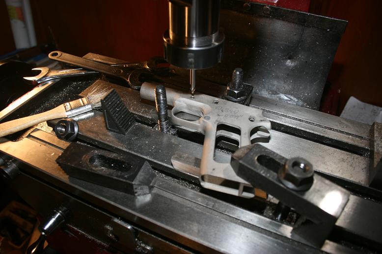
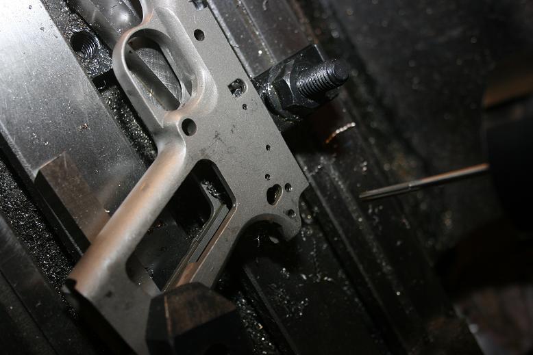
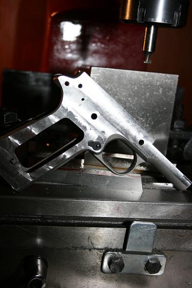
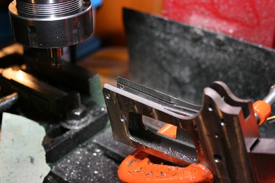
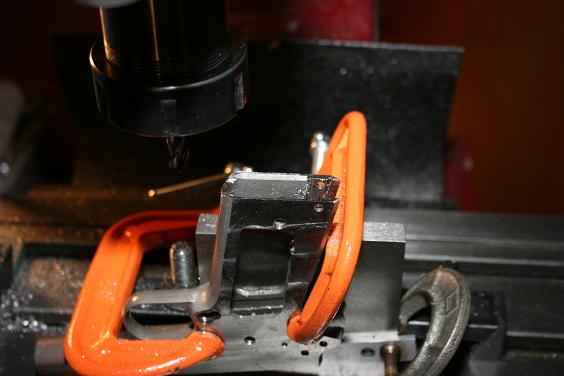
For the next setup I did the mag release area. I keep an angle plate bolted to my mill table that is indicated parallel for a handy reference for setups. For this I used two angle blocks to rotate the frame 17 degrees relative to the angle block. again I bolted the frame down on my ground blocks.The origin (0,0) is the mag release hole cast into the frame.
I zeroed a 5/16" long endmill on the frame and bored the mag release hole (0,0) 0.695" deep (there's a step - don't bore through).
Through the center of the hole just milled, bore through with a 0.290" (L) drill. This creates the shoulder the button rests against
I used a jig (from another member) that used the holes in the frame to align it properly and allow you to use a center punch to mark all the remaining hole locations. took about 5 minutes to mark all the holes. while I have marked my hole locations I have not done anything else (too busy) with the receiver, so I'm watching this thread with great interest.
A slot needs to be milled for the tail of the mag release. Plunge with a 7/32" endmill to half the thickness of the frame at (-0.227",0) and mill back to the origin (0,0).
Next is a fun cut - Zero a 5/16" x 0.050" keyseat cutter on the frame. Plunge to 0.110" at (0,0)(leaving 0.060" above the top of cutter to top of frame). Mill toward muzzle 0.055" (0.055",0) forming the slot that the cam on the mag release fit into.
All complete!
> If you don't mind, where did you find a .050 keyseat cutter. The closest I > could find is a .0469 X 5/16.
I went and miked the cutter I have and it mikes 0.0469 (3/64") despite the tube saying 0.050". The gov. print say 0.050" +0.005", but one pass with the cutter I have allowed the mag release cam to seat just fine.
Thats what I thought unless you take a 1/16 X 5/16 which would be a 302.5 and grind it down to .050.
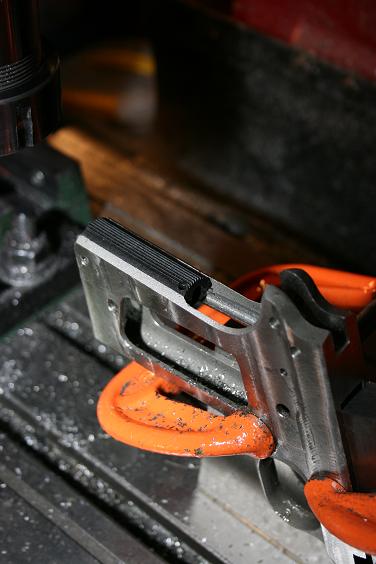
Did some more work on the frame this week (not much). I did the manual safety slot next. Working from the left side of the frame rotate frame 18 degrees relative to top deck and zero off the center of the grip safety pivot hole (0,0). I used the angle plate and angle blocks again for this setup.
First order of business is to mill a slot 0.210" x 0.404" wide to half the depth of the frame. This slot is centered on the grip safety pivot and 0.465" away. Since I do not have a 0.210" endmill I used a 13/64" endmill and made two passes. The tool path for a 13/64" endmill would be: (-0.461",-0.101" to - 0.461",+0.101") & (-0.469",-0.101 to -0.469",+0.101") for the second pass.
Next plunge with a 0.25" endmill to half the frame depth at (-0.5035",0). This forms the clearance bubble at the front of the slot.
Last operation for this setup is to mill the undercut for clearance of the safety notch. For this cut you need a 0.25" dia. keyseat cutter. Thickness is not important as you can take more than one pass. This undercut starts 0.066" below the surface and continues down to the hammer slot. I used a 0.25" x 1/16" keyseat cutter so I had to make 4 passes to reach the hammer slot depth. Zero the cutter off of the top of the casting and plunge to 0.066" plus the thickness of your cutter at the location we plunged for the bubble (- 0.5035",0). The cut we made with the 0.25" endmill also provides clearance for our keyseat cutter. Once at the proper depth (top of cutter 0.066" below top of casting) mill to (-0.512",0) this gives us our starting point. Mill the undercut from (-0.512",0 to -0.512", -0.101") then to (-0.450",-0.101") then to (-0.450",+0.101") then to (-0.512,-0.101) then return to (-0.512",0) forming a rectangle under the surface. Plunge the thickness of your cutter and repeat the sequence untill you reach the depth of the hammer slot.
Safety installed.
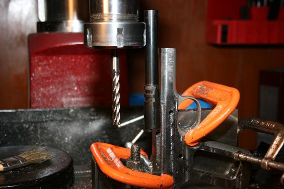
I have been away from this project for a while due to a couple of discouraging problems - 1st, I machined the mag catch incorrectly. if you look back to the middle of the first page of this build you can see that I machined the mag catch recess to the correct dimensions, but, angled the frame nose down instead of nose up. Argh! I will weld it back up and machine it correctly later. 2nd I could not locate a commercial slotting saw with the correct dimensions to form the sear hammer slot (3" dia. ,1/2 spindle, .312" thick.). I have come up with an approximate solution shown here:
It is 3-3/8" dia. , .312" thick, and has a .75" shaft and cost $13.00 to build. Note the reverse rotation to avoid loosening the nut. Here are the constituent parts:
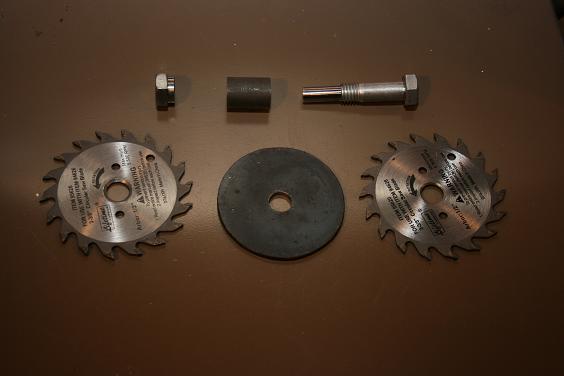
2 3-3/8" dia. HF carbide circ. saw blades sandwiching a 5/32" x 3" dia. plate held together witha 1/2" NC bolt and nut that have been cleaned up to run concentric to the .375" shaft turned on the end. Also included is 5/8" ID, 3/4" OD custom washer/spacer.
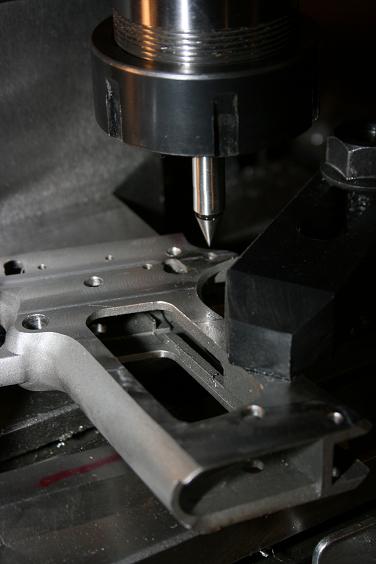
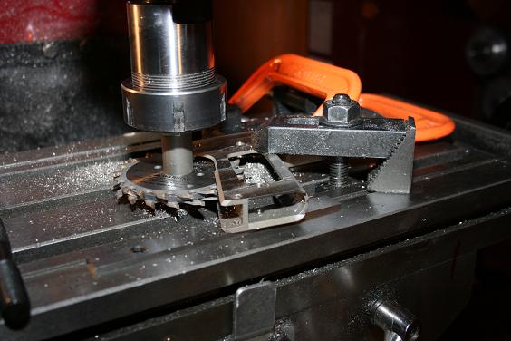
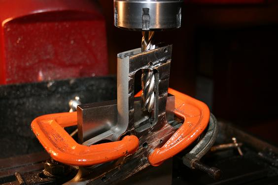
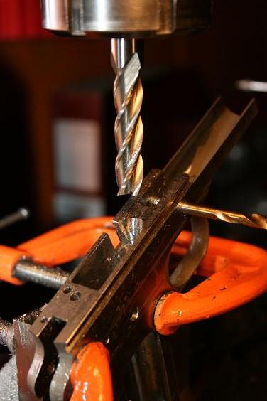
Here is the setup for cutting the hammer/sear slot (if you use my method/cutter make sure you run your machine in reverse!):
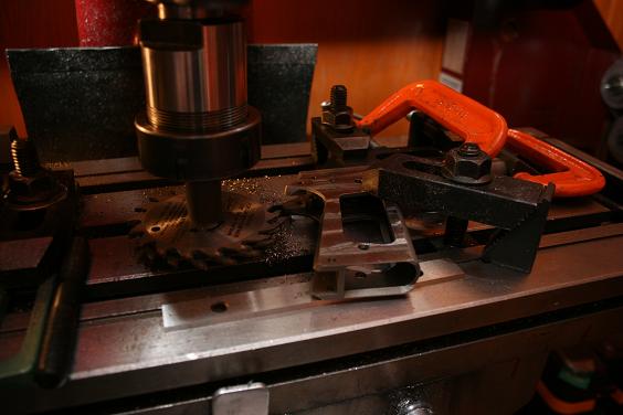
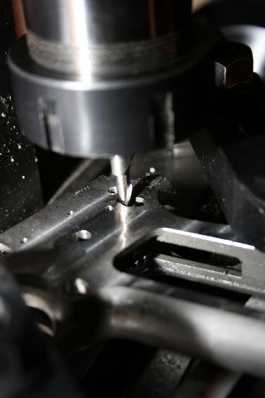
The origin for this cut is the slide catch pivot hole (0,0) and the centerline of the frame. Since I have substituted a 3.375" cutter for the proper 3" dia. one I milled to -3.918",-0.932" instead of -3.768",-0.792" as on the original. I came up with these dimensions by laying out the cuts in AutoCad and compromising with a correct cut in the critical hammer/sear area ending up with a longer slot into the grip area.
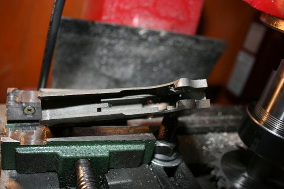
Note how much further the slot extends into the grip using the larger cutter - I did not take a pic. but the trigger and sear fit perfect. I do not forsee a problem with the extended cut since there is still ample support for the mainspring, but I would not recommend following my method until I have mine complete.
Setup frame at 17.5 degrees and zero on the centerline of frame and the center of the mainspring housing pin hole. I used a .375" endmill for this pocket.
Mill the pocket 0.542" wide and 0.195" down from the centerline of the pin hole (-0.195"). Mill as far up the back of the frame as possible (almost to the "ears") I suggest a 3/8" or smaller endmill for this to be able to reach the end of the pocket.
Using the same setup mill the slot for the multifunction spring. It is located 0.420" from the centerline of the pin hole to the start of the slot. The slot is supposed to be 0.040" wide but I used a 0.0625" endmill. The slot is 0.400" long centered on the frame. The slot is millled through into the mag well and the coordinates for a 0.0625" endmill are 0.440", -0.170" to 0.440", +0.170".
That completes this setup.
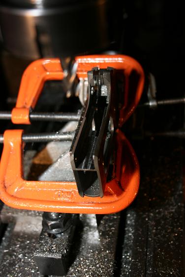
Setup frame at 23 degrees and zero on the centerline of frame and the mainspring housing pin hole. The keyway for the mainspring housing starts 0.086" up from the center of the pin hole (+0.086") and is 0.627" wide. I used a 5/64" (0.078") x 0.5" carbide keyseat cutter (another use for the cutter I purchased to cut the sear slot on my 1919) and made the cut in 1 pass down each side of the frame. I ended the cut in the transition to the grip safety area as seen in the pic. ( I did not mill to a precise length)
Pic. of the mainspring housing installed
Setup frame at 8.5 degrees. zero y axis on centerline of frame and z axis on centerline of mainspring housing pin hole. Deck the bottom of grip frame to 0.138" above center of pin hole (+0.0138") mill slot at front of grip frame for the toe of the magazine 0.510" wide to 0.053" above center of pin hole (+0.053").
This is a quick simple setup
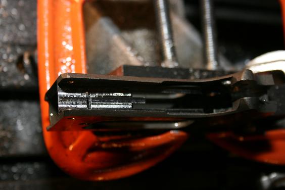
Setup the frame at 17.5 degrees. Establish y axis zero at centerline of frame. Using an extra long 1/2" endmill touch off of the back of the mag well to establish x axis zero. Follow this path to mill the bottom half of the mag well: 0, -0.029" to -0.900, -0.029" to -0.900", +0.029" to 0, +0.029".
Setup frame at 9.0 degrees. Establish zero as before (centerline of frame, touch off of back of mag well). Using same extra long endmill follow path 0, - 0.029" to 0.900", -0.029" to 0.900", +0.029" to 0, -0.029".
This completes the machine work for the mag well - all that remains is a little filing to square the back corners - and it fits!
Nice work and good thinking, i have been working off and on the same frames. the only thing I did different was buy a 1/2" slitting saw arbor that accepts 1/2" to 1" holes on the saws and bought the 3" X 1/4"with 1" arbor hole from Whosale Tools and made 2 passes. Then I used a 1/16" cutter on the rails for the mainspring housing and made two passes on that.
TR6 - I found 3" saws with 1" arbors but I did not think it would mill far enough into the H/S slot without hitting the arbor. How did you get it to work? I scratched my head for a while contemplating the use of one of those.
A piece of 1/2" hot roll with some silicon carbide sandpaper masking taped to it. I have seen similar setups that have a slit down the middle to hold the paper, but I have had no problem with just the tape holding it. just make sure you use enough paper to wrap past the tape.
For the frame rails I use a special MOON CUTTER 1/2" X 3MM X 1/2" which is 0.118" so it leaves very little filing with the rails close to 0.119". Check the MOON WEBSITE http://mooncutter.com/
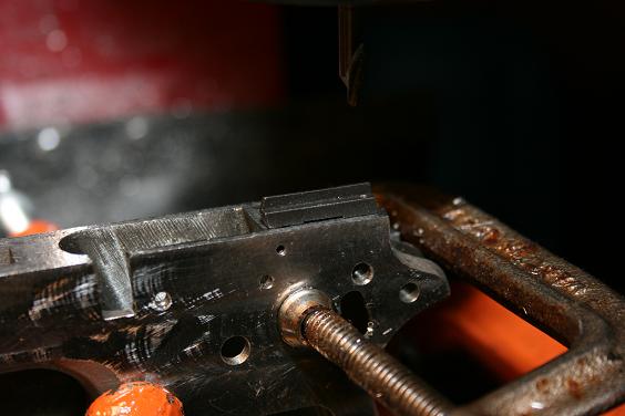
I chose to mill the takedown lever slot through the top of the frame. this is not how it was originally done, but I like the way it looks and it prevents a crack from developing in the thin web left if milled from the side. To machine the slot this way set the frame at 4 degrees relative to the top of the frame (4.5 degrees relative to the bottom of the grip). zero the x axis on the centerline of the takedown lever pivot hole (0,-,-). Move toward the back of frame 1.080" and touch a 7/32" endmill off of the top of the frame to zero the z axis (1.080",-,0). Machine at this location 0.450" deep (-0.450"). Widen slot to 0.238" wide (1.100,-,-0.450") to finish.
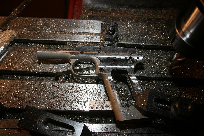
Takedown lever is fit
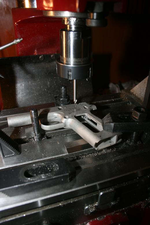
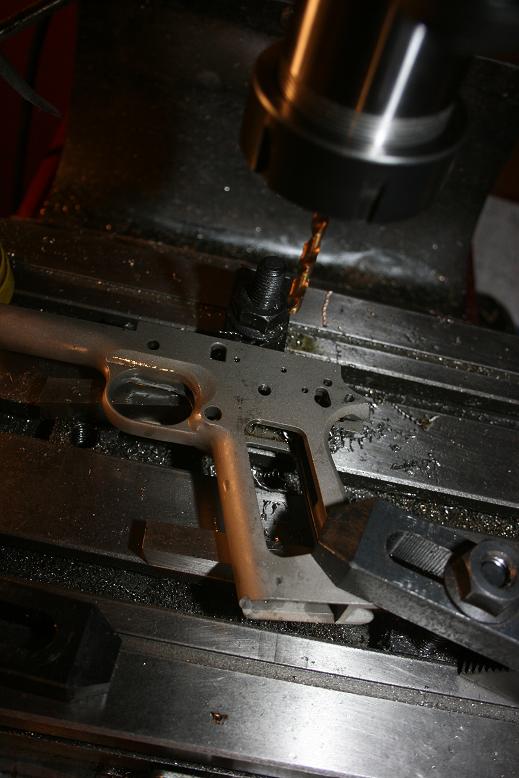
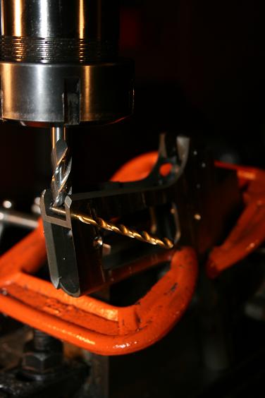
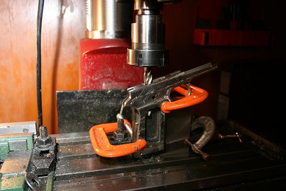
The disconnector hole proved to be a little bit of a challenge. start by setting the frame at 6 degrees relative to the top of the deck (2.5 degrees relative to the bottom of the grip as shown). Zero the x axis at the centerline of the takedown pin hole and the y axis on the centerline of the frame. Move 2.475" (-2.474",0,-) toward the back of the frame and drill through with a #19 drill (0.166")
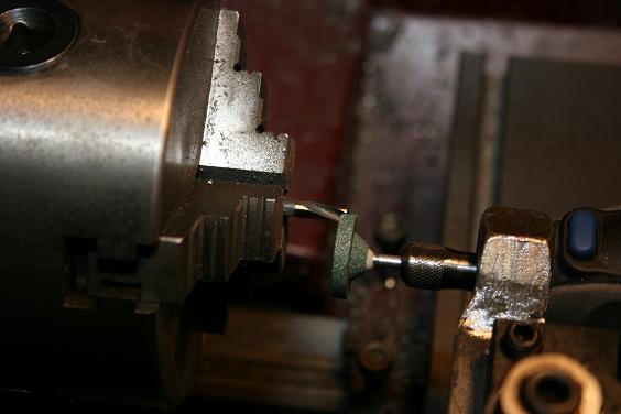
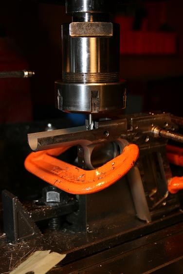
To form the step on the bottom side of the disconnector hole I had to make a piloted drill. I started with a 6" 7/32" drill and chucked it in my lathe - here is a pic. of my low buck home job tool post grinder.
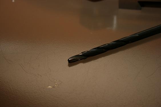
7/32" drill ground down to 0.166" for approximately 1/2" to form pilot. To complete the tool I dulled the cutting edges of the 0.166" dia. part.
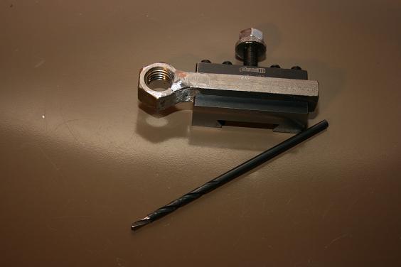
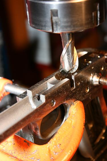
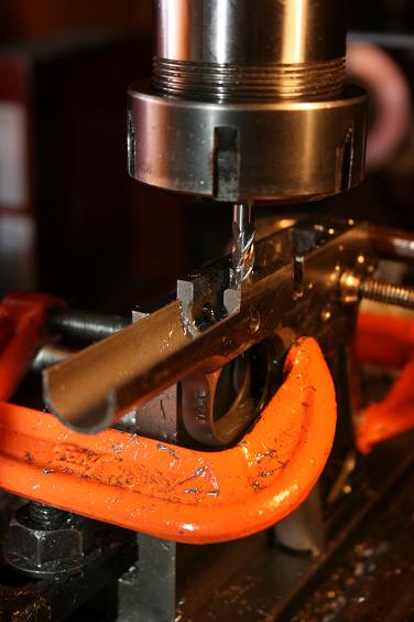
Completed drill alongside my Ghetto Grinder Adapter. Adapter is a 3/4"x10 nut welded to a piece of 1/2" x 3/4" bar stock to fit my tool holder and dremel tool.
Closeup of tip - be sure to dull the flutes in the reduced dia. part to avoid cutting pilot hole oversize.
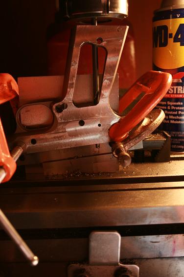
Set frame at 6 degrees and establish same zero as before ( centerline of takedown pin hole). Move back 2.475" (-2.475",0,-) and counterbore to within 3/16" of top of deck and the hole is complete. I scribed a mark on the drill to let me know when I reached finished depth.
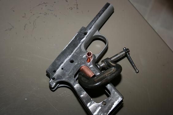
Here is how I fixed the mag. release cut mistake that I made. First some copper pipe to back up the welds.
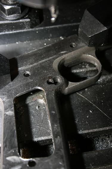
A little welding, milling flush, and re-cutting the slot with a 7/32" endmill (17.5 degrees the correct way!) and it done. It would definitely be better to do it right the first time.
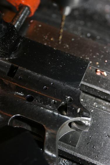
Next I drilled the hole for the ejector retaining pin. This hole was not on any of the prints that I have so I missed drilling it when I had the frame setup on it's side. The best I could determine for the location of this hole is 2.328" back from the centerline of the take down pin hole and 0.150" down from the top of the deck (2.318,0.150", through). This hole is 0.0625" dia. and drilled through the frame. This is an awfully deep hole for a 1/16" bit so be careful.
With the top deck surface indicated parallel to the mill table zero x-axis on the center of the takedown pin hole. Zero y-axis on the drivers side edge of the frame. move to (2.391",0.148") and drill a 0.125" dia. hole 0.330" deep. Countersink this hole 0.02" x 60 degrees. Move to (2.967",0.133") and drill a 0.096" dia. hole 0.125" deep. Countersink this hole also 0.02" x 60 degrees. This completes the holes for the ejector.
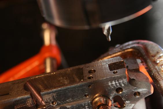
Ejector in place.
For the remainder of operations from the top of frame zeros are: x-axis - centerline of takedown pin hole, y-axis - centerline of frame, z-axis - top of deck. Zero 5/32" dia endmill on top of deck. for barrel link clearance slot move to (-0.439,0,-0.654") mill slot back toward rear of frame 0.594" (.155",0,-0.654").
I do not have a 0.700" dia ballmill, so I approximated the barrel channel cut with a 0.625" dia ballmill like this: Zero 0.625: dia. ballmill on top of deck. On centerline of frame mill channel 0.077" deep (-,0,-0.077") from magwell to dust cover. Widen slot 0.010" each way (-,-0.010",-0.077") & (-,- 0.010",-0.077") to complete.
Mill the barrel lug clearance slot with a 0.25" dia endmill. Mill slot 0.300" past centerline of takedown pin hole widening the slot to 0.365" wide making passes 0.058" each way of frame center (-0.400",-0.058",-0.400") to (0.300",- 0.058",-0.400") to (0.300",+0.058",-0.400") to -0.400",+0.058",-0.400").
The 1911 frames from sarco do have a bit of meat to them. My thoughts on a left hand build: (1) The mag release hole is undersized enough to machine either hand. (2) There are partially formed holes for the slide stop and safety in the casting already. These would not be a problem to weld up to start fresh on the right side of the frame. I welded up the mag release mistake with 70 series wire with no problem. Milling the slide stop and safety slot without benefit of partially formed slots is no harder from scratch if you folllow the method I used. (3) Ejector could be installed on either side of the frame no problem. (4) I wish I had your idea when I started - that would be a cool 1911 (I'm left handed too - I just ignore that fact most of the time) Oh, yeah, post pics. if you take on this project!
More machining of the frame:
For the rails I used a carbide 0.5" dia. 5/64" thick keyseat cutter (my
favorite cutter - useful for slotting 1919a4 bolts). I zeroed this cutter on
the top of the deck and moved down 0.178" to begin cutting the rails. I did
not cut the rails by the numbers, rather I did it this way. At 0.178" down I
touched the cutter to the side of the frame. I knew I needed the slots to be
0.067" deep each side of the frame so I machined the slot 0.050" deep and took
a measurement of the frame and the slot to be sure I was at 0.050" depth. if
not I could adjust to get the 0.067" depth. Since my cutter was only 0.078"
thick I had to make two passes to get the 0.119" width. This process was
repeated on the other side.
I then used a 5/8" dia. endmill to to mill 0.005" of each side of the rails for a final width of 0.751". Also I machined the end of the rails 0.361" forward of the takedown pin hole 0.219" down (-0.361",-,-0.219") to mill the dust cover to proper height.
With the frame mounted perpendicular to the table I zeroed the x-axis on the centerline of the takedown pin hole, the y-axis on the center of the frame. With a 5/8" endmill zero z-axis on the centerline of the takedown pin hole (touch a drill stuck on the hole with the endmill and move down 1/2 drill dia.). The print calls for a 0.358" dia. cut for the inside of the dust cover 0.089" above center of takedown pin hole. I used a 0.625" dia. endmill and followed the path (-0.5",-0.018",0.361") to (-0.079",-0.018",0.361") to (- 0.079",+0.018",0.361") to (-0.5",+0.018",0.361") to mill the inside of the dust cover.

With a 29/64" long endmill bore the barrel/spring seat 0.431" deeper than the centerline of the takedown pin hole at 0.089" above center of takedown pin hole and center of frame (-0.089",0,-0.431").
Now to finish the barrel lug slot. All that needs to be removed is the radius at the back left from the 0.25" dia. endmill. Zero a 5/16" dia. endmill on the centerline of the takedown pin hole. Set cutter depth to -0.431". Mill slot 0.365" wide to within 0.089" of center of takedown pin hole (-0.5",-0.027",- 0.431") to (-0.089",-0.027",-0.431") to (-0.089",+0.027",-0.431") to (- 0.5",+0.027", -0.431").
Checking barrel fit.
The feed ramp for the .45 caliber version is bored at a 31.5 degree angle perpendicular to the top of the frame within 0.79" of center of takedown pin hole. I set the frame at 23 degrees to the bottom of the grip (31.5 - 8.5 degrees). Zero the x-axis on the centerline of the takedown pin hole and the y- axis on the center of the frame. With a 29/64" endmill move to (-1.016",0,- ). At this location bore through to the magwell to form the feed ramp.
Time to check the slide and barrel fit! Don't forget to lightly chamfer the corners of the rails before trying slide. Also file a 1/16" chamfer at the intersection of the barrel trough and barrel lug slot. The project is starting to look like something now! Only a few operations left.
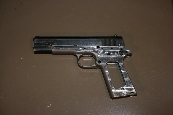
That is a 1918 colt 1911 slide (not 1911A1) that I picked up a while back. I know the kidney cuts make the frame incorrect for the gun , but I am pretending that it had its frame replaced as an arsenal rebuild.