I just received my first 0% 1911 castings and am hoping that some of you out there will help me put together a gameplan for machining these things.
Woah tall order Marvkaye, but you know what they say where there is a will etc.
I guess since the magwell might be quite trying I would say start there. Once complete I would probably work on the mainspring/disconnector/sear track area. You could also drill the holes in the sides first because if you mess that up at least you would not have much time invested. I would save the dust cover/guide rod seat for last so you could use that area to clamp to if necessary and not crush frame.
Things of note that I think might be difficult but not impossible are the trigger bow area inside the magwell and the trigger slot and the magwell.
Thanks for the thoughts, Chris. I like your ideas. I agree on the holes first... at least that way I can get the primary -T- reference (slide stop pin) hole done and have my ground zero established.
For starters I thought I'd plane down the top surface and open up the trigger area, then locate the -T- hole based on the trigger opening. Once that's done, getting the rest of the holes drilled should go pretty smoothly.
I've been looking at the frame from my Daly and am trying to put together a plan of attack for the mag well and mainspring/disconnector/sear track area. The latter shouldn't be too tough, as once the proper angle is established I should be able to get most of that done with a plain end mill cut, followed by a keyseat cutter for the tracks. Once I've established that as my new reference plane I think I can drill out the front surface of the magwell and use an 1/8" drill to locate the magwell back corners... mill away the rest and square up what's left of the inside rear corners with a nice sharp file. Actually, after the inside front of the magwell is drilled and the open areas on the sides of the magwell are cut with a 1/2" end mill, there isn't that much left of it to machine... just the top and bottom. Make sense to you?
This should keep me occupied for awhile... perhaps I can get started tomorrow or over the weekend.
If I had a chunk of aluminum that approximated the shape of the castings I'd probably do a practice run, as suggested... I just don't want to spend all that time when I could be applying it to the real thing. Should be fun.
PS... the drawing I purchased from William (tanneryshop) doesn't include the trigger bow area. I'm going to check out the drawing area here to see if I can locate a better drawing.
Just my input. 0% casting all dim. need machineing if so I would find the center of the casting left to right. Finish machine one side to finish dim +.010 from center then you have a surfice to lokate off of to do the rest of your machining.
Id still like to know how your gonna do the trigger bow area. I was watching the thread about the billet frames cause I would like to do the same. I program and run 2 cnc machining centers and a wire edm at work and havent figured out a good way to do the trigger area except with a really long 1/4 inch cutter then a file. The rest would be relatively easy machining. What about making a 2 piece frame and tig welding it together. I saw a write up at one time from someone who bought an 80% and it was a 2 piece
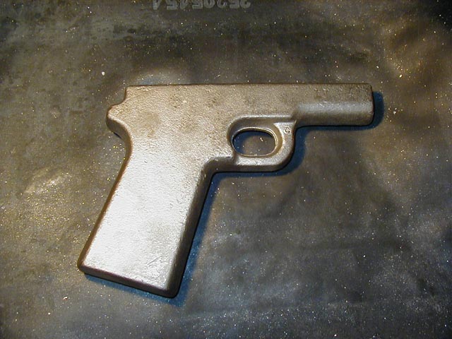
This is what the raw chromoly casting looks like. It has a little "c" in front of the trigger guard identifying the material. The other one has an "s" there for stainless.
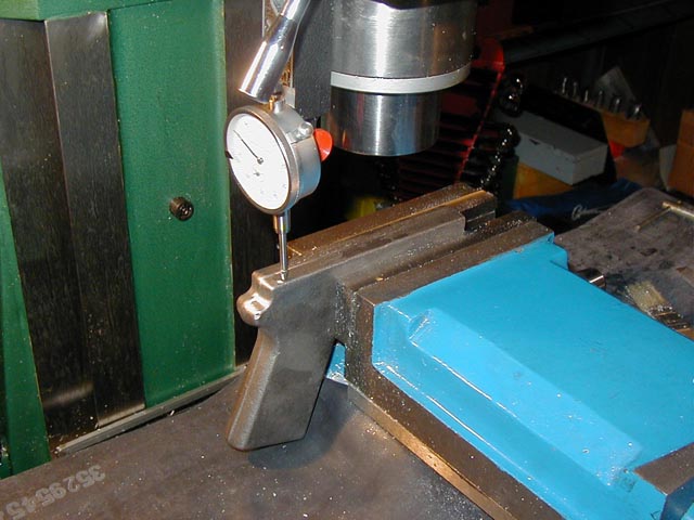
The next pic shows me levelling the frame in the vise, getting ready to plane off the top. The casting had a bit of a roll in it across the top next to the parting flashing so I had to hit it with a file for awhile to get it smooth enough to indicate. You can kind of see the flat spots just this side of the parting line, about the middle of the frame top.
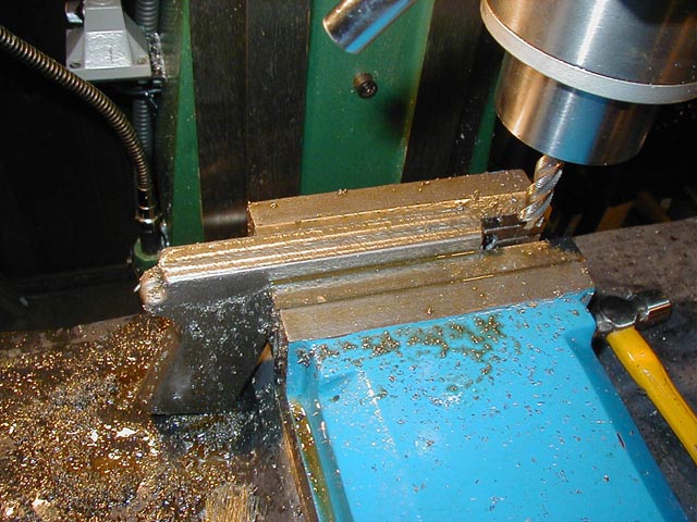
Here's the top being planed flat. That's a 1/2" 8% cobalt roughing mill... I should have used a shorter and fatter plain end mill... this one flexed a bit so left me with a lousy finish. I really didn't care about that, so long as it was flat enough to provide a good gripping surface, and it was that. I'll be smarter next time I grab for that cutter. BTW, I used good old sulphur-based thread cutting fluid for lubricant. Worked great and made some neat clouds a bit later on. You'll see.
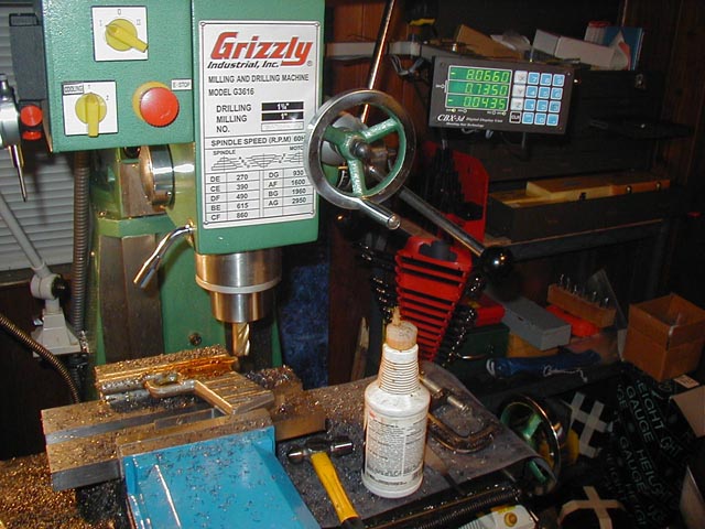
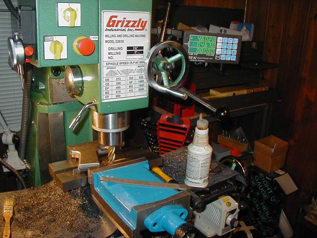
After the top was planed I setup some parallels to support the frame on its side and started milling the left side flat. You can see the z-axis readout on the DRO... this pass was at .0435 down from the unmilled surface (I roughed at about .010 each pass). The frame started out at .850, so the final pass this side was just .0015 to finish out at .805. Gameplan was to take the same amount off the right side to wind up at .760. It worked.
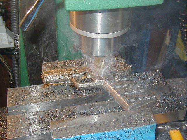
Letting the genie out of the bottle... the cut was a bit too aggressive and there wasn't quite enough fluid to keep the heat down. I used more later. Fortunately there are no smoke detectors in this place.
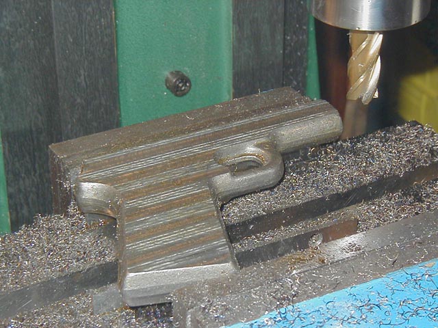
When I flipped the frame over to work the right side I kissed the supporting parallel with the face of the cutter to establish the bottom surface. That's a 4-flute TiN-coated 3/4" end mill.
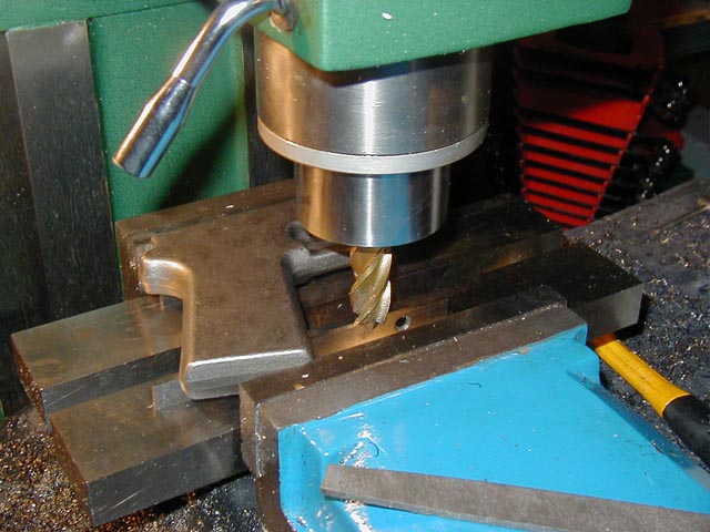
With the cutter kissing the parallel I re-zeroed the z-axis.
I then lowered the knee until the z-axis read .760 to establish the desired finish thickness of the frame. Once I'd established where I wanted to end my milling I re-zeroed the z-axis, lowered the knee further until I was clear of the frame and started cutting the right side.
Five passes later, this is what the right side wound up looking like.
I wasn't real happy with the finish, as I don't think stripes are in this year. As I mentioned earlier, I really need to re-tram the head on my mill. That will eliminate the swirls and my need to file/stone everything back into submission. I should have done it before starting but I was just way too anxious. Now I get to do all that extra work. Good thing this is a hobby.
BTW, the depth of the swirls is actually just a thou, maybe a scoche more, so I was able to pretty much eliminate them with a file and stone. I'm waiting for a slab of granite so I can lay the frame on a piece of 320 grit and sand the last of the marks out. It really shouldn't take too long, I just wish I had done it right in the first place.
I also discovered that my vise jaws actually lift the workpiece slightly away from the supports when I crank down on it. The vise feels nice and tight and exhibits no perceptible play in the jaws, at least not until I clamp down on the stock. I'll figure something out to help with that part of the battle, though, I'm sure. Anyway, as a result, the frame now varies in thickness from .753 to about .747, the small dimension is up at the dust cover. Given that this is the first real steel anything that I've worked on and probably the most demanding cutting that I've done with this mill, I'm pretty satisifed. As long as I learn from the mistakes and build on the experience (and don't make any really stupid mistakes, like holes or notches or something else mislocated) I think this thing will turn into an actual 1911 sooner or later.
So, whaddya think? Is this way too cool, or what?? We're having fun now!
  Would a few taps from a rubber mallet or plastic-head hammer set the part
down properly on the parallels as you tighten up the vise?
You may have noticed that there is a small ball peen hammer sitting on the bed next to the vise... light taps from it would persuade the frame into position during most of the levelling operations. Normally I can get a part to stay married to the parallels just by holding it down with my free hand while tightening the vise, but in this instance that didn't work. The last crank of the vise handle would always remove that pressure from the parallels.
I chose this vise because the fixed jaw is machined as a part of the vise frame, as opposed to being a separate part that is attached to the lower ways with a slot and bolts. A local machinist who has been providing me with guidance when needed told me about the problems with attached-jaw vises versus solid cast ones, and that's why I chose this particular vise. I suspect that because the part is being held at the very top of the jaws the tightening of the part causes the movable jaw to pull against the lower gibs and close the thousandth or so of clearance that's required to allow the movable jaw to move. I'm going to see about tightening it up just a bit to minimize this situation. When I clamp a part deeply in the jaws (just sitting on an 1/8" parallel laid flat in the floor of the vise) I don't experience this situation at all.
I used a transfer punch to mark the location for the slide stop pin hole
center, then a center finder to align it with the mill.
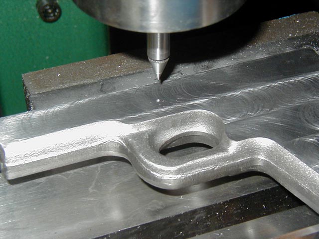
That center finder is fine for getting within a few thousandths of the actual center of the punch mark, and obviously close enough for this particular operation. The barrel and movable pin of the center finder are ground to the same diameter, and it's up to the operator to see the alignment of the edge of the pin's base with the barrel. I'm pretty sure that as long as I'm wearing my readers I can see that +/- .002, but I wouldn't sign anything that committed me to being any closer than that. Once the hole is drilled I'll use my co-ax indicator to locate on its exact center when I reset for later milling operations or whatever. I'll show its use later in the program.
PS... BTW, this is hardly a tutorial, Prof Merlin... I'm sharing this so the more knowledgable out there will point out the error of my ways and help others who attempt this to get it right the first time. I'm glad you're enjoying it, though... me too.
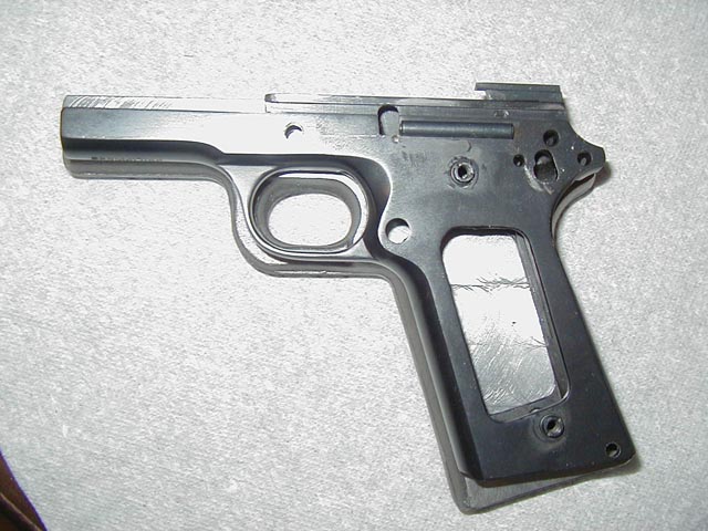
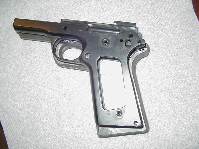
Here's a photo of the holes that are done.
While we're talking about this, has anyone out there got a suggestion for how to do all that complex milling required at the hammer area? I was looking at my Daly frame and can't see how some of that machining was done. Suggestions will be greatly appreciated.
Been following along here but haven't jumped in yet * great job so far & thanks for the pics. As far as the reamers go -YES! I think that is by far the best way. I have a 70% alum fram that needs these same holes - I just sent travers an order for the tooling (I can dig up the list if you'd like w/all the needed reamers/ drill bits & sizes) I was suprised by how much it ended up costing me. I think I spent less than $35 on the reamers for all fire-control holes i was expecting it to be twice that. as for the milling of the hammer/sear area I think that would have to be done with a keyseat saw to acheive that circular part in there, as far as the back channel I'd guess a nice fat center-cutting .540 endmill should do it? right? I'm just guessing here - I've never tried a 0% before, but I'm glad you are.
Hey D.T..... I'd sure be interested in seeing that reamer list. There are some weird sizes in there, although I don't see it as much of a problem... most are available within a thou anyway.
One of the other tool problems I see is finding the proper roundover cutters. No problem finding a 7/16 radius in either a corner rounder or possibly a concave cutter, but some of the other specs are a bit more complicated. Like finding a 13/32 radius cutter, or 17/32 radius. Just got off the phone with a friend of mine who's in the cutting tool business and he said I'd have to have those kinds of things custom ground. I've started to put my own list together and am attaching it here. Hopefully you and others will check it out and insure I'm not missing anything. Thanks for the help. (I've used prices from my friend's catalog, as it was the most complete one that I had at hand. Any suggestions about less expensive options would be great. All tools listed are HSS unless noted otherwise.)
Here's that file. I haven't started on the roundover bits or any of the other cutters (for the rails, endmills, external contours, etc) but will add them in the next few days (I hope). Pretty expensive to buy all this stuff at once, and there's lots more to go. Time to start saving them sheckles.