With a spiffy new lightweight trigger in place, it seemed only fair that better trigger function should follow. The work outlined below does not require the services of a gunsmith, but it does require: access to good information (see Part 1 referenced sources), the ability to follow instructions and a good supply of patience. Since parts are modified, experience with finishing or fabricating hand tools is helpful. If these resources are not available, it is better to have the work done by a reputable gunsmith.
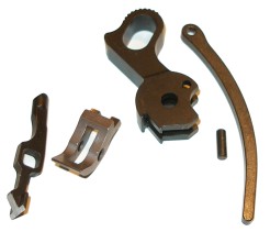
Drop in replacement parts are available from a number of sources, most offer two product types; factory grade replacement parts and upgrade or enhanced parts. The former are of about the same quality as the parts that go into the High Standard GI 1911; cast, surface hardened, complete with parting lines on contact surfaces. The latter type parts are significantly better than standard. The Nighthawk set sold by Brownells falls into the enhanced part category. They are machined from solid bar stock and are nicely finished. As pictured; disconnector, sear and hammer, the price tag is about $90. The strut and strut pin are Colt parts that add another $10. By comparison, factory replacement grade parts run about a third less as a set.
Outside of replacing worn or defective parts, the worth of both grades of parts is subjective. The parts will drop in and function properly, however, the gun's thumb safety will probably require refitting to engage and clear the new sear properly. In regard to the lightened hammer decreasing lock time, the stock hammer assembly weighs 0.8 ounces, the light Commander type weighs 0.7 ounces. I didn't stop to do the millisecond lock time reduction calculation but, in defense of the hammer, it is nicer looking than the stock piece. To get to a light trigger pull, basically the same work required to modify the High Standard factory parts is required on these drop in replacement parts. As a point of reference, installing the drop in Nighthawk parts without modification yielded a very clean but 5 lb 12 oz trigger pull. The descriptive text below addresses modification of stock parts, however, toward the end I did note the installation differences for the Nighthawk parts as I did go on to complete the trigger job utilizing these parts also.
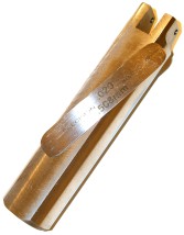
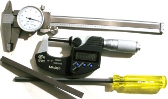
I personally would not attempt modification of parts without a sear jig of some type. It is too easy, in the absence of a jig, to cut the sear too short, or at the wrong angle, or not parallel to its pin axis and create a potentially dangerous situation. The simple tool, pictured right, is made by Ed Brown and sells for approximately $37 through Brownells. Its use is not a one time deal, as sears wear and eventually require dressing and/or replacement. There are fancier sear jigs like Marvel Precision's Ultimate 1911 sear jig, but they are priced in the $115 range and too costly for this project. Brownells manufactures the Bob Marvel 1911 Auto sear and hammer jig. Priced at $149.00 the jig facilitates modification of both sear and hammer, a capability beyond the models noted earlier. If I were going to work routinely on 1911 types, I'd buy this one.
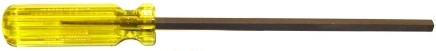
Hammer squaring files are convenient. They are very similar to an extra narrow or narrow pillar file with two opposing cutting sides and two safe sides. They can be laid on the hammer flat while squaring the hooks and will not cut down into the hammer. A hammer squaring file runs about $35 from Brownells, a common narrow pillar file with safe edges sells for about $16 from Brownells or any number of tool suppliers. A cutting or polishing stone can't be substituted for this task as stones are not of precision shape and worsen with use. Consequently, they will not make a sharp square cut. A stone would leave radius at the base of the hook rather than a sharp right angle and it would cut into the flat at the base of the hooks.
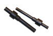
Trigger adjustment pins fit into the hammer and sear pin holes in the gun's frame. These permit the gun's hammer and sear to be mounted externally for a visual check of engagement angle and surface contact prior to actual assembly. Brownells sells them for about $30. Assembly/disassembly becomes a very easy proposition after awhile, and trial fitting the complete set of spring loaded parts, then checking for proper contact with Dykem is probably more precise then relying on adjustment pins. In keeping with the concept of a low buck gun and trigger job; avoiding the purchase of rarely used or specialty tools, I believe I would purchase the Ed Brown jig, a 6" pillar file with safe edges and skip the trigger adjustment pins.
There aren't a lot of parts that figure into trigger function and feel. In the sequence as numbered they are: disconnector, sear, hammer, main spring and sear spring. The variables effecting pull are smoothness of contact surfaces, the depth of hammer/sear engagement and the spring rates that force the pieces together when the gun is cocked. Reduction of trigger pull resistance and creep come from reducing the degree and persistence of friction...or maybe stiction.
Personally, I don't like ultra light triggers on rifles or pistols. I'm good down to about 3 ½ to 4 ½ lbs of pull with short take up, no creep that clean break. There is some resistance I need to feel before the trigger breaks that gives me a final target/steady check. When a pull begins with take up and slides right through trigger break with little difference in resistance, I never feel steady on target.
The rearward motion of the trigger, with the gun cocked and slide in battery position, is transferred to the sear through the disconnector. Operating details appear in excruciating detail in all of the reference material indicated in Part 1. There are some things to check and some cleanup that can be performed to improve trigger function.
                    Item    Drawing         High Standard

  Frame Disconnector Port   0.164"+0.003"   0.165"
       #1 - Ball Diameter   0.155"-0.004"   0.162"
               #2 - Width   0.285"-0.008"   0.284"
           #2 - Thickness   0.035"-0.005"   0.036" (0.035" after polishing)
            #3 - Aperture   0.174"+0.004    0.076"
      Disconnector Length   1.293"+0.009"   1.299"
                        A   0.825"-0.005"   0.824"
                        B   0.476"-0.004"   0.474"
                        C   0.307"+0.005"   0.308"
Item #4 is a relief cut that assures the disconnector doesn't peek through
the frame and get bumped by the inserted magazine. Why the mind numbing data
recording? The record will be of great help when I take the gun apart after
some use and I want to check for wear. Baselines for a gun that will be worked
on with some frequency eventually saves a lot of time and helps to predict the
useful life of assemblies or modifications. The disconnector ball diameter is
not out of spec. The drawing referenced is for a cylindrically cut
disconnector, while the High Standard has a pivot head disconnector identified
by its ringed diameter. This design cuts friction, while maintaining a tighter
port fit.
This is an example of where inexpensive guns demonstrate why they are...inexpensive. The cast parts carry parting lines on contact surfaces, they are roughly finished and hardened to an undetermined depth. All of this adds up to undermine the potential for a slick trigger.
There is sufficient material on the factory piece to permit rework, for those who choose to rework rather than replace with a drop in piece, the stock disconnector can be cleaned up with a stone and it will still be in spec.
I used relatively soft bonded aluminum oxide stones. I started with 400 grit for primary cutting than went to 600 grit until the finish was polished. If you can see the bow contact face of the disconnector, there is still a slight surface blemish from a casting sink mark above the contact surface. This is OK. I wanted to generally smooth out the irregular surface and get rid of raised parting lines, but I didn't want to thin the part out of spec or work through the surface hardness. Less than 0.002" of material was removed. I did not touch the top of the disconnector, as the slide contact surface was actually smooth.
The relationship between the sear and the 1911 are a little like the relationship between Michael McDonald and the Doobie Brothers; the sear defines the gun's personality more than any other member of the group and, if your remove it, the rest stops working. When the 1911 pistol is cocked and the trigger is squeezed, the rear of the trigger bow pushes against the disconnector, the disconnector pushes against the sear hooks, the sear pivots out of engagement with the hammer, causing the hammer to fall.
As a minimum, before reinstallation, the sear deserves a check of dimensions and a look at its general condition to assure: the disconnector isn't dragging on sear hooks, the hammer engagement surface is smooth and properly formed, the sear is of adequate length, the sear pin hole isn't excessively worn, etc. An out of spec or improperly modified sear can result in a hammer that follows a closing slide, a bound disconnector, unintentional discharge, doubling, full auto operation and, even worse, a truly lousy trigger feel.
Item   Drawing         High Standard
   A   0.404"-0.003"   0.406"
   B   0.249"-0.004"   0.247"
   C   *   *
   D   0.030"-0.003"   0.047"
   E   0.111"+0.002"   0.110"
A This dimension was reduced to 0.402" when the sear was reworked.
C by drawing is a radius reference measurement , not a direct measurement but should have approx 0.030" engagement with disconnector when cocked and in battery position.
D Sear surface was reduced to 0.025"
I could have checked the sear for damage and proper length and then polish without altering its dimensions. However, the engagement surface was thick enough for snow removal and irregular across its width, so a little touch up seemed appropriate. There was also unequal contact between the disconnector and sear hooks and some disconnector drag.
As mentioned at the onset of Part 2, truing of the engagement surface and/or hooks is not something to do freehand. Without guidance it is impossible to hold the surface parallel to the sear pin axis or uniformly control the thickness of the engagement edge. There are some great products that will serve this purpose well and adapt to a variety of guns, but I don't think it is necessary to invest in a piece of semi automated equipment more suited for a shop applications. For as...frugal as I can be, I broke down and bought an Ed Brown sear jig from Brownells for $37. I liked the idea of being able to control the modification and the satisfaction of accomplishing the work on my own. By the same token, it was nice to have the assurance of using a proven piece of tooling that would allow me to do the job properly
The slot in the nose of the Ed Brown jig allows for the sear to slip in with virtually no side play. The cross drilled hole permits the gun's sear pin to be used to retain the sear in the jig. The jig's sear angle adjustment screw is preset and locked at the angle Ed Brown, Inc. applies when performing a trigger job. Yes, the jig can be adjusted for other angles more suitable to a skilled user's preference. What does that mean?
Unless you have an educated and proven basis for a change, accept the manufacturer's predetermined angle and utilize soon to be noted functional checks to verify proper operation. I'm not being a techno-snob, or even overly conservative. The stock part drawing indicates the sear's hammer contact surface is to be perpendicular to a datum line, that is a clockwise rotation of 25°6', from another datum line, that is 0.249"-0.004" from the undercut flat surface of the sear that is located just above the sear hooks. When I discovered 25°6' could not be measured with a thermometer and ruler, following the suggestions of the tool's designer seemed the next best plausible action.
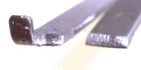
The Ed Brown jig is supplied with a 0.020" thick piece of shim stock and instructions. It is amazing how many manufacturers do not include instructions these days. In the photo on the right, my index finger is pressing the sear against the adjustment screw, which locates the sear's engagement surface relative to the upper surface of the jig. Placing the shim on top of the jig and against the sear limits the amount of material that can be removed by stoning. This prevents the sear from being cut too short and rendered unusable. The shim also acts as a leveling guide for the stone and protects the jig from damage from the stone; shim stock is cheap and replaceable.
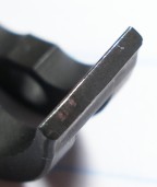
With the sear anchored by sear pin, and positioned at the proper cutting angle by pressing the sear tail against the jig's adjusting screw, a 600 grit stone was laid on top of the shim and pushed over the sear's surface until an even flat surface was established. It is better not to stone all the way down to the level of the shim so material is left for future clean up. When I was done, the depth of the sear engagement surface was approximately 0.040" and the sear height was still 0.402" and in spec. Then, as instructed, I cut a 45deg clearance bevel on the leading edge of the engagement surface until the surface width was reduced to 0.025".
I've seen general purpose firearm sear width as low as 0.020", but I thought this would be a good compromise until proven otherwise. I wore a 6x magnifying visor, took my time, and resisted the temptation to make one more touch up cut. it is hard to see here, but the finish is somewhere between mirror reflective and satin. Other than a very light touch with the stone to transits from the clearance angle to the engagement surface everything was left alone. This is not a place to break out a Dremel and polish or rub on an abrasive saturated cloth as any non-rigid material could round the engagement surface and render the sear unsafe.
Editor's note - In response to questions received. If, when checking engagement, the hammer side surface of the sear below the clearance cut contacts the hammer flat and prevents the surface from coming into complete engagement with the hammer hooks, material needs to be removed as part of fitting. Approximately 70° angle will usually do the job. These types of adjustments apply to virtually all gunsmith parts fitting. Visual and operational checks tell you when they are required.
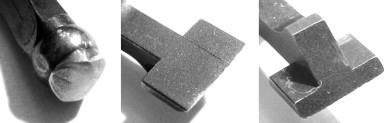
Sort of looks like a running kangaroo. When the sear work is completed the job is only half done, as the corresponding hammer surface needs to be cleaned up also. This is outlined in the instruction packaged with the sear jig as well as in any of the reference material noted in Part 1. There are many reference dimensions that cannot be easily verified to the part's drawing, as the datum lines and other points of reference require the use of specialized measurement tools and equipment. For that reason I stuck to the areas that were specified and defined by instructions and were verifiable as correct.
The hammer's sear engagement notch was finished to the same depth as the sear engagement surface; in this case 0.025". In addition to notch depth, adjusted by stoning the hammer hooks that form the notch, the hooks were trued to 90° with hammer file and cleaned up with a 600 grit stone. Finally, the outer surface of the hooks were restored to the original contour so no part of the radius protruded further than the height of the hooks so the hammer would fall unimpeded. care must be taken to keep the hooks on the same plane so the sear is supported and released uniformly.
As you can see in the picture, I only removed the fuzz from the long horizontal flat at the base of the hammer hooks. A reduction in the distance between the hammer pin hole and this flat can cause the hammer to follow the slide.
There is no substitute for trying parts for fit and contact. When the disconnector, sear and hammer were being worked, I installed, removed and reinstalled them without the grip or thumb safety in place. The omission saved time and offered better visibility of the working assembly. Checking rub marks on contact surfaces coated with Dykem made it easy to quickly and accurately determine if proper contact had been achieved. The process is repetitious, possibly tedious, but it ends with the assurance parts have been correctly modified.
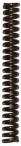
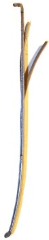
Buried in the mainspring housing is a piece that has a significant impact on trigger pull. After all of the fancy handwork, footwork and hand tool juggling, eventually the reality will set in that main and sear spring rates mostly determine trigger pull. A change in the mainspring rate is a bit of a balancing act. Heavy springs will increase trigger pull, the light springs will decrease pull but, at a certain level, a light spring will make the gun more sensitive to the effects of trigger bounce or an unintended hammer fall when not intended. There is also the possibility of a very light spring causing too light of a primer strike and, subsequently, unreliable ignition. Rate and compressed resistance are relative as commercial guns and many military pieces do not follow the published spec for the 1911.
The mainspring housing is a relatively simple assembly. There are at least a couple of ways it can be disassembled without getting popped in the head with a flying spring. As shown in the bottom right inset, you can place a grip screw against the mainspring cap, tighten the arrangement in a vise with the broad head end of the mainspring cap pin facing down until the mainspring is depressed and its retaining pin drops out. Then vise can be opened gradually until the spring is unloaded. The second way is to hold the mainspring housing in one hand, press on the mainspring cap with a cap size punch with the other, cap pin head facing down. The pin will drop out and you can ease out the punch until the spring is unloaded. Reassembly is the same, only in reverse, unless you selected method #2. You do push the punch in to compress the spring, but you have to be a nice enough person to warrant having at least one friend who can drop the pin in when the spring is compressed. A funny thing about standard documentation, it often differs from reality. The first thing I did was check the rate of the stock spring. The mainspring housing well depth measured 1.680" from bottom flat to top flat surface. The pin retainer from spring contact surface to edge of parallel surface measured 0.155", cap thickness measured 0.146" and distance from outer housing to the loaded cap measured 0.128" (includes cap retaining pin diameter). To get to installed spring height; 1.680 - 0.155 - 0.146 - 0.128 = 1.251". To check the spring rate, as well as the rate of possible replacement springs, I had to check spring resistance at the compressed length of 1.062", or after 0.146" of travel where a stock spring is suppose to read approximately 29.5 lbs +/- 2 lbs.
I don't like to flaunt the high dollar tools, but there is no way around it as a spring tester is required. I put the nose of a punch against the mainspring cap, measured out 0.189" and filled in the space with felt tip pen. Then with the punch against the cap, I pressed the top of the punch against a digital postal scale until the 0.189" mark on the punch was level with the mainspring housing, and took a scale reading. The following are relative readings to gauge change, not absolute readings.
Dimension                     Drawing  High Standard  Ed Brown 19#  Wolff #18#
Compressed # Spec @ 1.062"      29.5    -             19            18
Compressed Lbs Actual @ 1.062"   -      19.2          18.5          16.4
Free Length "                   2.156   2.052         2.160         2.148
Installed length "              1.251   1.194         1.194         1.194
Hammer Strut Stoke "            0.224   0.224         0.224         0.224
Compressed Length  " *          1.027   1.027         1.027         1.027
Coil Diameter "                 0.273   0.270         .268          0.265
Wire Thickness "                -       0.044         0.044         0.042
* Coil bind at approximately 0.968"
I measured hammer strut stroke by installing the mainspring housing without the grip safety. I put a pencil mark on the strut with the hammer down, then another with the hammer cocked, then I removed the mainspring housing so I could measure the difference between the two marks. It was the easiest way I could think of to get to an approximation of compressed spring length. I elected to go with the Ed Brown 19 lb spring. The thought was I would try the heaviest of the light springs first, then drop lower only if required to assure reliable primer strikes.
How significant is the main spring rate in regard to trigger pull? I reassembled the gun, minus the grip and thumb safeties but with slide installed to protect the frame, and did a pull test. The results, after a dozen or so cycles was 4 lbs 1 ounces and very crisp, with little creep and virtually no snap, crackle or pop.
No, this section is not about how to protect your thumb, it is about building a safe gun. The thumb safety blocks the rotation of the sear away from hammer engagement when the safety is in the "on" position as pictured above far left. When the thumb safety is rotated to the off position, a relief in the thumb safety's sear stud faces provides clearance for the sear to rotate clockwise and out of engagement with the hammer - above right. Please don't get hung up on the exact location of the parts, they are only roughly arranged, but the block - unblocked illustration is a good approximation. A gun's thumb safety needs to be checked whenever the disconnector, sear, or hammer are modified or replaced. Any dimensional change in these parts has the potential of moving the sear far enough away from the safety's sear stud, when the gun is cocked, to permit the discharge of the firearm with the safety in the "on" position.
The easiest way to check safety/sear position and alignment is to partially assemble the gun; sear, disconnector, hammer, sear spring, mainspring housing - which makes for an operating gun without a grip safety blocking the view. In this case, the unmodified safety checked out OK so no further work was required.
The Nighthawk parts are, as indicated earlier, nicely finished and machined from solid bar stock rather than cast. There are a few comparative differences from the High Standard parts, beyond material.
The disconnector is missing the relief cut that is needed to assure it clears when a magazine is inserted. This can be remedied with a 0.020" flat placed on the radius with a file. Where the High Standard piece has a ball end, the Nighthawk piece has a cylindrical end. The one I received had some radial tool marks that grabbed inside the frame's disconnector port. A little polishing of the surface with a Dremel solved the problem.
The Nighthawk sear, as received, was approximately 0.004" taller than the High Standard piece and the engagement edge was a fat 0.035". Additionally, the pad that contacts the thumb safety sear stud was 0.020" thicker than the stock piece. I ran the sear through the Ed Brown sear jig as I did the stock piece, and cut the relief angle deep enough to reduce the engagement depth to 0.020". I left the pad thickness as received and cut the thumb safety for proper clearance as pictured left. In addition to cutting the stud surface for safety "on" position, the back side of the stud needs to be contoured to permit rotating the safety to the "off position. Thumb safety installation and fitting is covered in detail in the next series installment.
The Nighhawk commander style hammer hook high, approximately 0.028". I cleaned up the angle with the squaring file, then cut them down to 0.020". I did not stake the strut pin, but rather let it float between the hammer and strut, with the frame preventing it from falling out. Other than noted, the piece was a drop in. When the gun was reassembled, the trigger overtravel had to be readjusted to suit the new part dimensions.
I put the gun back together as a basic assembly, and read the trigger pull as 5 lbs 12 oz. There was a little creep and much to heavy for my taste. I disassembled, die marked and poked around, finding nothing obvious. Then I remembered reading a great article written by Jack Weigand, "2 ½ lb Trigger Pull", not for the 2 ½ lb trigger pull, but for a helpful technique and reference weights for setting sear spring tension. The manual suggests not going below ½ lb for the disconnector finger and 1 lb for the sear finger. Weigand's article suggested 16 ounces for each where a 3 ½ lb trigger is desired.
I gripped the spring from the tab end with a large pair of channel lock pliers, careful to clear the tab. The tip of the jaws gripped just at the crest of the arch where the spring would make contact with the installed mainspring housing. Then I bent back to reduce preload, a little at a time, checking with a digital trigger pull scale. The gun was clamped in a vise and the grip safety was removed so I could be certain I was first checking only the disconnector spring reading before the trigger picked up the sear finger and compounded the reading. Each was adjusted precisely to 16 ounces for a combined of 32 ounces. The sear and disconnector fingers ended up on approximately the same plane, the grip safety spring was left alone. Trigger pull was 3 lbs 4 ounces.
The contact tips of the springs were very rough, as though they had been chewed off. These were stoned just enough to smooth them without effecting their length or temper.
What was more interesting was the very significant impact the changes had on group size. 15 yard groups went from two hand hold five shot groups of 3" down to group of less than 2". That's a big improvement from an item that effects the shooter's ability to point the gun more than improving the gun's accuracy. I'll take it. The changes had no ill effect on firearm function, including no loss of reliability. I will stick with the parts upgrade approach, at least for now and move on to installing an extended safety for Part III.