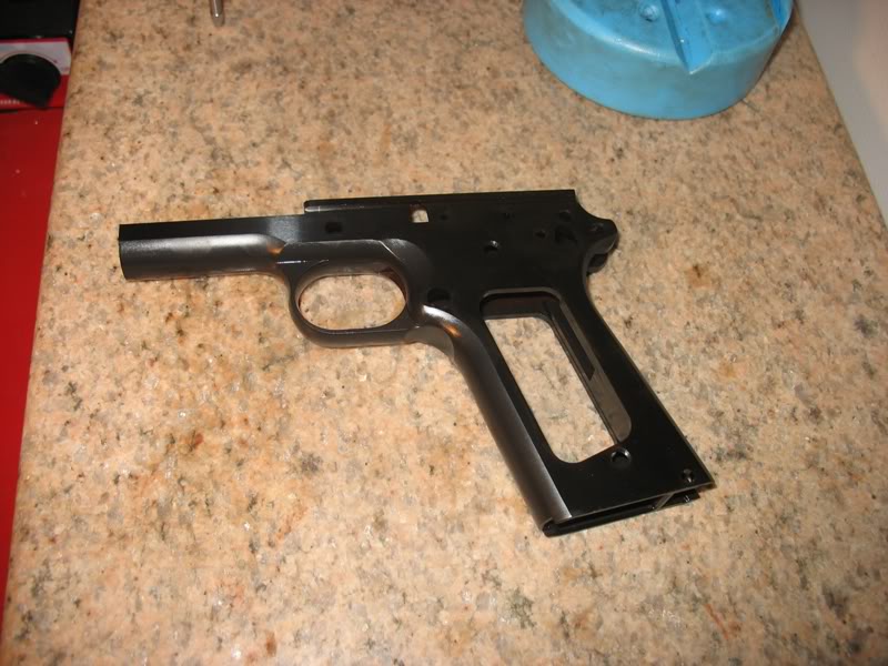
I have been planning my next build for a while now. I hope to build (attempt) a target 45 over the next year to spread out the cost.
I budgeted a frame for one month. A slide for the next month and so on.
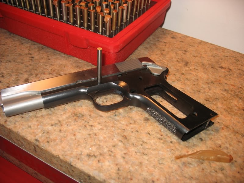
So far I bought a Remsport forged match (over-sized) frame:
Here is the write-up from gunbroker:
This auction is for a government length match grade blued frame w/ smooth front strap. Manufactured by RemSport, a primary contractor of custom 1911 accessories. Fully-forged frame, from a solid 4140 steel billet and then CNC machined and hardened to close, rigorous tolerances (Rc 26-30). Top rails are cut to maximum dimensions and may require final fitting to slide. Frame has a .250" grip radius cut, is machined for standard and non-ramped barrels
This frame is of high quality metal and precision machined...vthan you Remsport... there is one complaint below...
Side view of Remsport Match Frame:

side view of Remsport Match Frame:
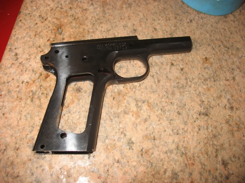
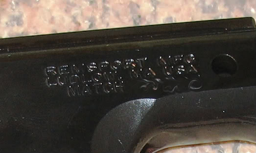
Frame marking shows that is the frame US made and I haven't decided if having the word "MATCH" in the serial number is cool or not but regardless of what I think the FFL transfer serial number was MATCH XXXXX
Front:
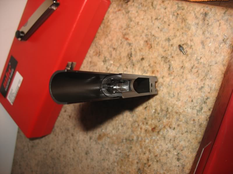
Now a word about the VIS:
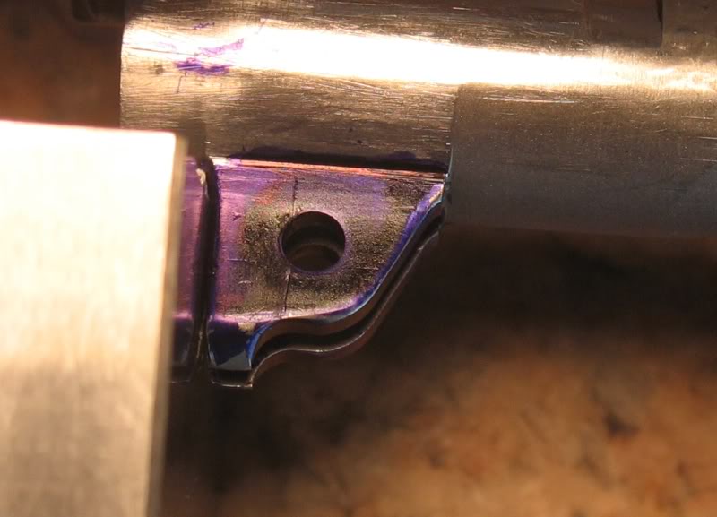
The Vertical Impact Surface (VIS) is a "sub-micro very shallow and skinny"
bow-tie cut with a massive chamfer cut between the barrel bed and VIS. This
large chamfer significantly lowers the top of the VIS and IMO reduces the
strength of the VIS. I will have to decide it I will let the barrel beat this
raised surface (Bow-tie) down or let the barrel hit the bed more... but
this is all in the future...

More frame picts:


Preliminary frame measurements:
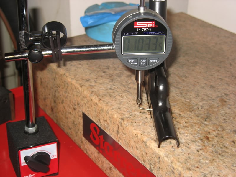
I don't own a groove-micrometer but I do have a very accurate drop indicator,
surface plate, gage blocks (cheap from ENCO) and feeler gages:
Initial rail measurements:
Zero:

Rail:
Gage blocks (ground to .0001) and feeler gage to measure the rail groove:
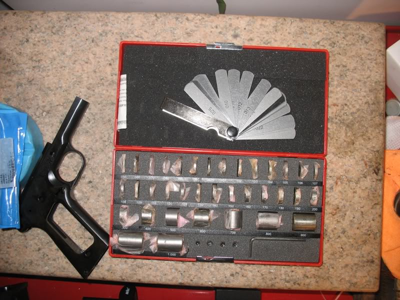
Results:

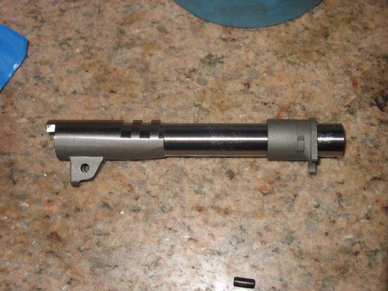
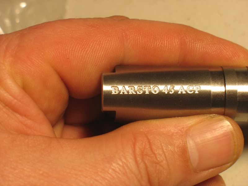
I choose a Bar-Sto barrel for this build after it was recommended by one of our resident guru target builders Jerry Keefer... thank you Jerry...
Bar-Sto barrels have a nice mix of history and 45-heritage and they are among the best barrels available.
Bar-sto currently has a 14-16 week lead time so I decided to put my name on the waiting list. Fortunately MidWay USA had one (they originally stated that the barrel was on backorder) so I got it a little early for my build:


Next I will select a slide (big $$$) which will probably be STI, Les Bear or Wilson. Then I will fit the barrel to the slide. Then I will buy a lug cutter and fit the slide/barrel to frame. Then... you get the story line...
I will report on my progress and thanks for sharing all of your .45 insight.
These parts look great! yeah, that VIS does look slim, but I'll defer that to the experts... and that's gotta be the biggest barrel hood engraving I've ever seen!
It looks like you're setting up for a really tight, accurate build here. i hope we get lots of pics - always cool to see, and I'd love to build a 1911 some day (after the laundry list of long guns I want to build).
Looks like you're off to a great start! I always get overly concerned with the outcome and have a difficult time making myself slow down and enjoy the process.
Quote:
The Vertical Impact Surface (VIS) is a "sub-micro very shallow and skinny"
bow-tie cut with a massive chamfer cut between the barrel bed and VIS. This
large chamfer significantly lowers the top of the VIS and IMO reduces the
strength of the VIS.
Too bad Remsport didn't just omit that straight chamfer. Would only take about 5 minutes with a knife or scrape to get the whole bow-tie.
I wonder if Remsport cuts them all like that or you ended up with a fluke?
That is a good call... perhaps I can call them... although I did read that some manufacturers chamfer the barrel bed... I just think that Remsport over- did the chamfer a little bit... this build will be a target pistol and not a range mule so it may not be a problem... fingers crossed...
quote:
The only Remsport slide I found was pre-fit to a frame... no
fun/challenge... and I couldn't (haven't) found a direct Remsport slide for
sale...
I forget the guy's name. When I spoke with him he seem willing to take the time to answer my questions; sounded like a good guy. You can order that slide direct.
Contact Info: Remsport Mfg
(413) 589-9976
Location:
(see map below) 566 Holyoke Street
Ludlow, MA. 01056
Mailing Address: Rcs Diesel Service Inc.
566 Holyoke Street
Ludlow, MA. 01056
Quote:
...although I did read that some manufactures chamfer the barrel bed...
The Ordnance spec for the barrel bed chamfer is 1/16" X 45°, and on a curved barrel bed the top surface of the VIS would also be curved as shown here:
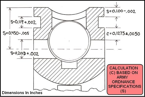
I'd estimate Remsport's chamfer has removed nearly half a third of the VIS's surface. But, like you mentioned, it might not be too much of a concern on a target gun with perhaps mild mid-range ammunition. Maybe. Hopefully.
But it was real eye candy to see a machined bar stock frame after all those photos of frames cast from ground up fenders off old rusty Subarus!
Wow! that is a lot of bevel.
Once upon a time Numrich gun Parts Corp had Remsport frames and slides. Don't know if they have any slides left.
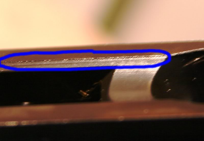
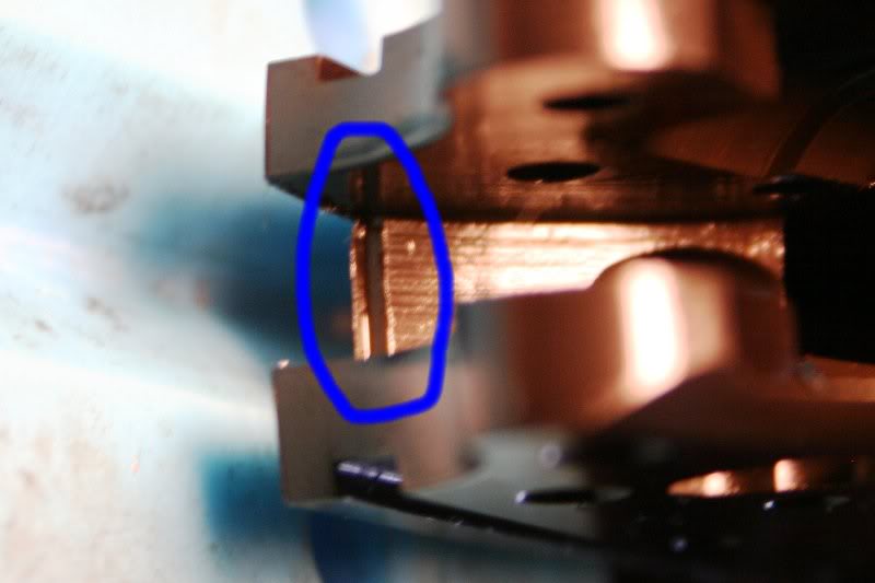
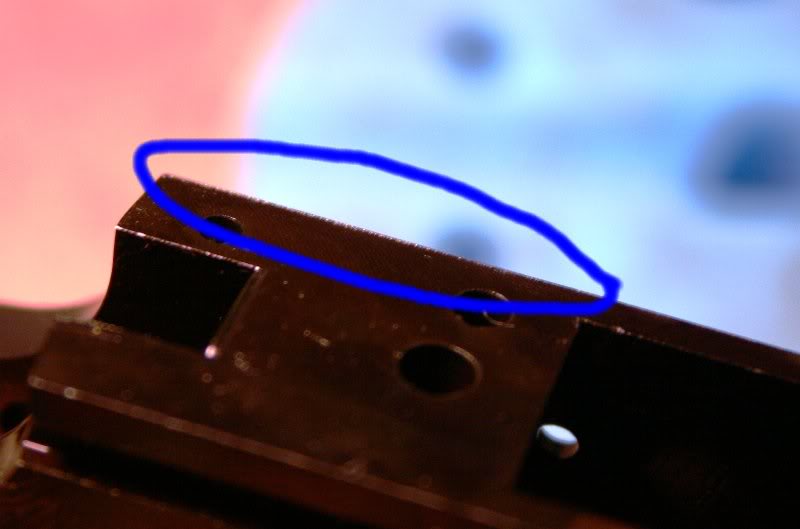
I looked that the frame again today and noticed some burrs left over from machining. I believe that these burrs will all be removed when I fit the slide but without slide measurements I can't say for certain.
Regardless, I will remove these burrs.
Quote:
If you want to borrow a lug cutter, let me know. I have the Brownell's tool
and the .186 cutter and don't plan a 1911 build for a while. Also, I assume
you've contacted Brownell's about a merchant discount? They are fairly liberal
with them and it's definately affected my loyalty based spending there.
Hello and thank you for the gracious offer... I may do this...
I want to buy a lug cutter because eventually I will buy a TIG welder and want to try to weld up some regular barrels and try to hard fit them like in the old National Match days...
BTW... I though .186 cutter was the first of two cutter diameters. The final lug cut should be cut to .195 to match the slide stop pin (under sized a little) and the .186 cutter is only used so the .195 cutter doesn't do all the work and wear out...
I'm curious as to what the cutter and cutter shaft look like.
I have looked at Kuhnhausen's jig and believe it can be made of wood and be perfectly acceptable, accurate and inexpensive to build. I haven't fully studied the problem but $80 for a cutter is more than I am used to paying for a single use tool.
Sometimes one does need to pay for specialty tools. I just don't believe I will be replacing a lot of 1911 barrels in the time I have left on this rock.
Here is what they look like:
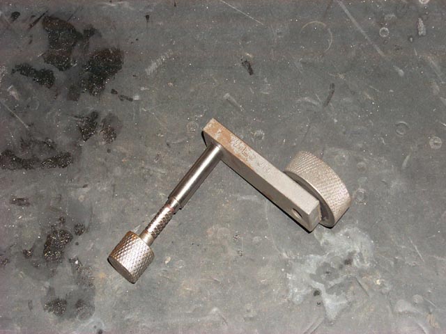
JK Vol 1 and II both show this same cutter... which cutter were you referring to?
Quote:
Once upon a time Numrich gun Parts Corp had Remsport frames and slides.
Don't know if they have any slides left.
I believe that this is the Remsport slide everyone is referring to and it is listed on GB sold by Numrich:
This auction is for a 1911 Goverment .45 Series 70 forged slide, with Front, Rear and Top Serrations. CNC machined and hardened from a solid 4140 carbon steel forging by a primary contractor of custom 1911 accessories (Rc 38-42). Features include surface ground flats, sandblasted round contours, 65 degree x .330" dovetail front sight cut and a Novak low profile rear sight cut. Firing pin holes are profiled for 9mm contour firing pins and barrel bushing bore tolerance equals plus or minus .001 inch. Fits the following models:
For $235 this is a good deal for sure but I want Bo-mar rear sight cuts because I want a fully adjustable target style rear sight and this one is cut for Novak.
I will call Remsport directly as Dave suggested in post #9 and ask if they can sell me one of their slides with a Bo-mar rear cut.
Waiting to hear how it all goes... You sound like you're WAY over my skill level.
Quote:
The Ordnance spec for the barrel bed chamfer is 1/16" X 45deg, and on a
curved barrel bed the top surface of the VIS would also be curved as shown
here:
Hello Niemi... I applied layout fluid to my Bar-Sto barrel legs so see how bad the contact marks look with the massive chamfer on my new frame...
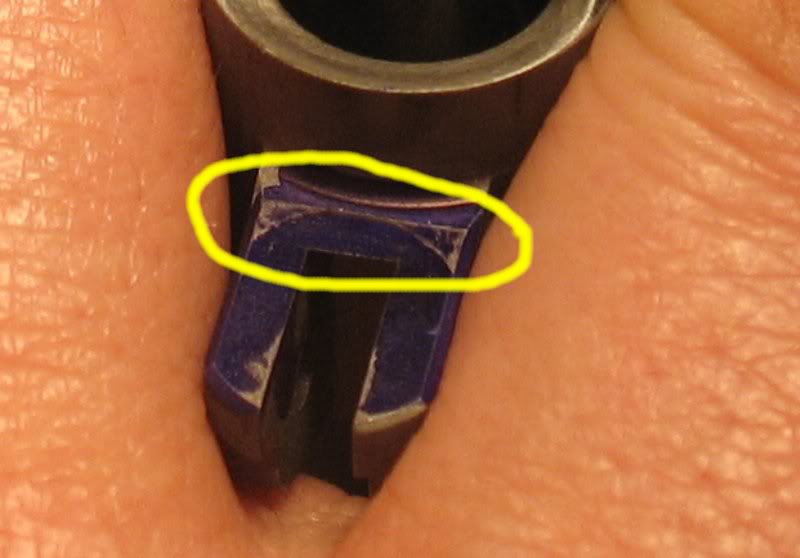
All is good... the actual contact marks are much higher than I expected... the high contact marks along with the fact that the bow-tie cut on the this frame is only about .010 deep means that once the barrel impact flattens out the bow-tie the forces will distribute across the entire barrel knees.
Not a problem... bring on the full power ammo.
Quote:
the high contact marks along with the fact that the bow-tie cut
on the this frame is only about .010 deep.
That's about twice as deep as the Army Ordnance spec of 0.005" at the maximum. My drawing in Post #10 shows how the VIS's bottom edge looks at half that allowable 0.005" mismatch or at a 0.0025" deep bow tie cut.
But I honestly don't know what all that means - if anything. Except maybe that when you get it all done and start shooting it, the faster-than-normal VIS setback might lead to faster-than-normal changes in linkdown timing.
But I tend to be a pessimist about this sort of thing and maybe act too much like a Devil's advocate. Cripes, I even talk myself out of doing lots of neat stuff!
This week's activities include the following:
Stoned down or removed bow-tie raised surface from VIS
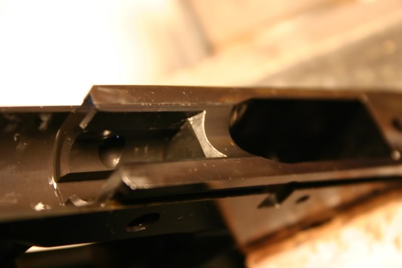
Honey, have you seen my bow-tie? I can't find it anywhere
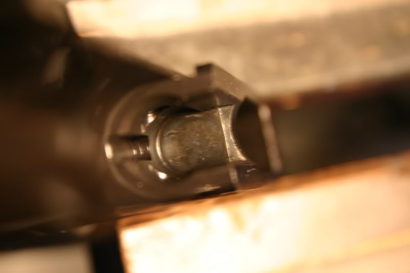
Lowered or relived the barrel knees at the area below the link pin.
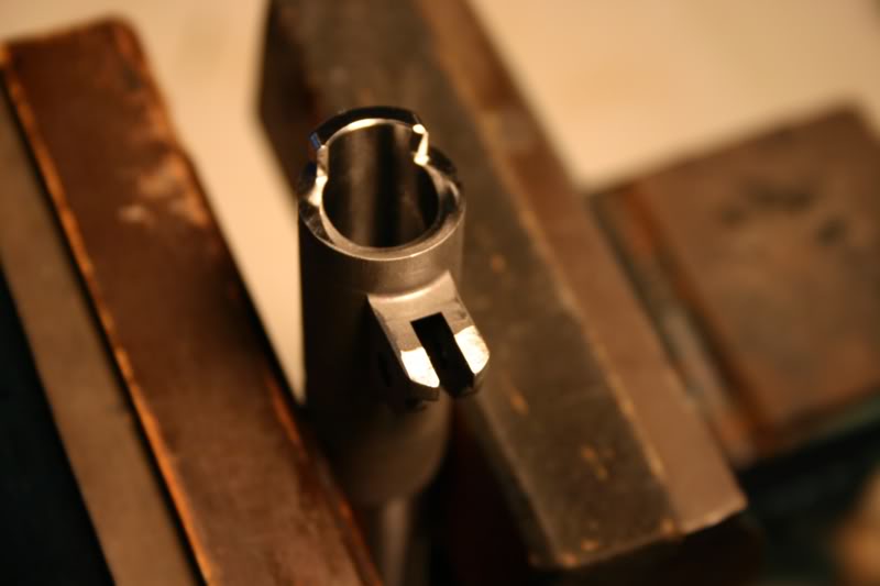
Now she off to be cleaned...
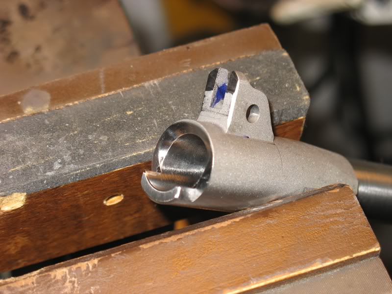
Hello Eric: If what you said back in Post #20 was fairly accurate...
Quote:
the bow-tie cut on the this frame is only about .010 deep
...now that you've removed the remnant of the bow tie cut you've also moved the VIS back that same distance.
Is the new VIS still within the spec'd distance from the SS pin hole center of 0.431 + 0.005 inch?
Quote:
Is the new VIS still within the spec'd distance from the SS pin hole center
of 0.431 + 0.005 inch?
Here are some quick measurements with digital calipers... not this best way to take the measurement but it will work for now...
Frame hole accepts a 201 gage pin not any larger.
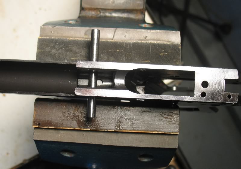
Right side measurement:
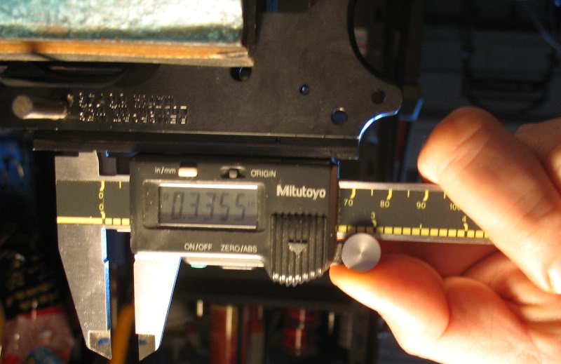
355 + (.201/2) = 0.436
Left side measurement:

335 + (.201/2) = .4355
Yes... just barely within spec at about .436 with the Mitutoyos and a gage pin.
I would like to add the reason I decided to eliminate the bow-tie cut was to eliminate any possible durability problems with the pistol. I decided that a larger VIS contact area would be better than the small bow tie cut. I only removed enough material to eliminate the bow-tie.
Quote:
Yes.... just barely within spec
Hot diggety! When I first read your post all I could think of was moving the VIS back 0.010" would be certain to put it out of its 0.005" tolerance. I guess the "about 0.010" deep" you posted was eyeballed, and all is well in 1911 Land.
Quote:
I guess the "about 0.010" deep" you posted was eyeballed, and all is well
in 1911 Land.
Your crystal ball is working fine... yes, it was a guess... I tried to make a putty mold and measure it's depth with no success... just frustration...
The tail (depth rod) end of my Mitutoyo vernier caliper is small enough to get a 0.009" reading of Petunia's bow tie cut. Even though that's lots more than the 0.005" allowable mismatch, it doesn't seem to affect anything. She still purrs like a kitten.
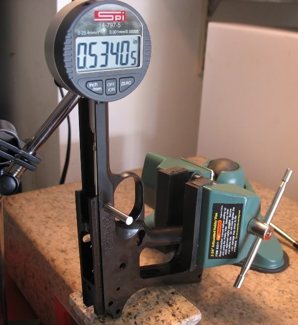
I did a follow-up double check of the measurement:
Zero on VIS:

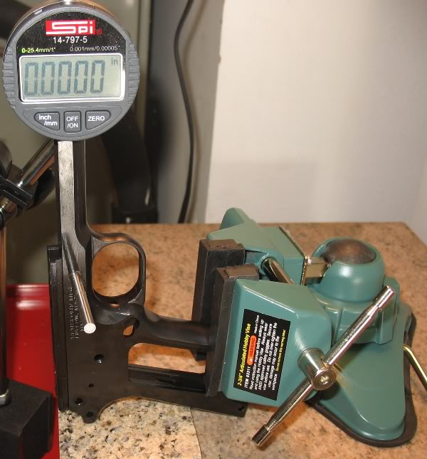
Measure 201 pin: .53405 (yea....its that precise)
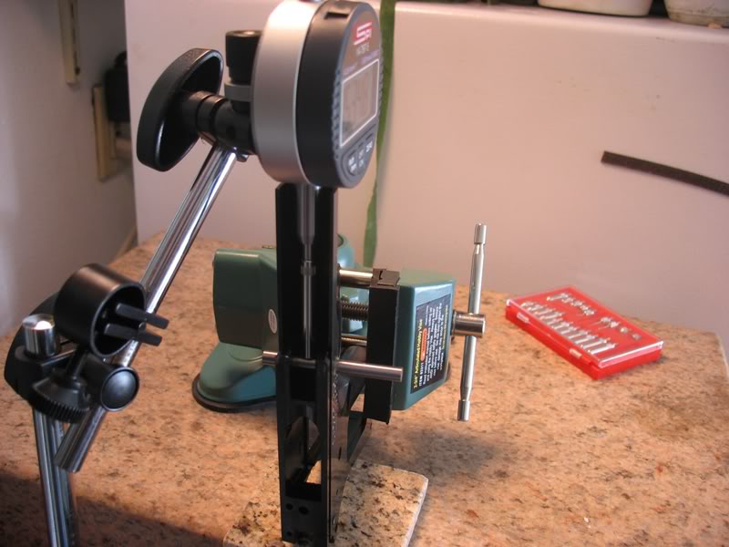
Check zero: ((-) .00040 off)
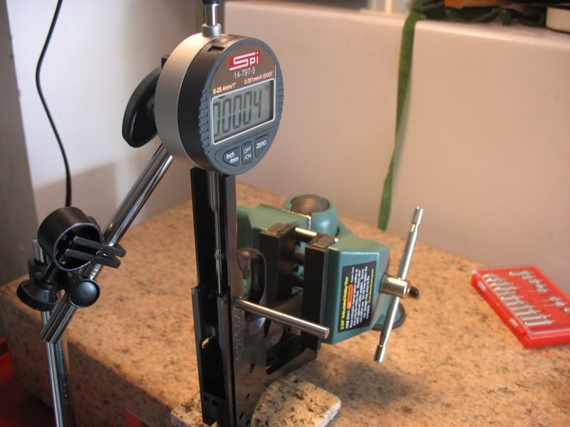
(-) .0004 off... I'll call it 0.43355 = .434-5 just to be conservative... still within spec.
Quote:
I would like to add the reason I decided to eliminate the bow-tie cut was
to eliminate any possible durability problems with the pistol. I decided that
a larger VIS contact area would be better than the small bow tie cut. I only
removed enough material to eliminate the bow-tie.
The bow tie is there for a reason... or at least it "was". You want your VIS contact to be higher on the feet, not lower. There is a really good write up about this on the other forum, but the gunsmith section has been down for quite some time...
Salvaged it...
This is a direct copy of a post made by Bob Rodgers, a VERY talented man who is not only a smith, but also runs his own 1911 course in Arkansas. Full credit belongs to him. I am sending him a message to make sure it's okay with him that I post it, so if I remove it later, you know why.
Mr. Rodger's website:here
(okay, the forum doesn't want to post the pictures, so I'll post a link to google's cached copy...
http://www.google.com/search?source...49be7798417a8e0
Quote:
The bow tie is there for a reason... or at least it "was".
I have drawn the conclusion, right or wrong, that a bow-tie VIS is not the best setup to stop the barrels rearward motion. As far as I know, a bow-tie VIS cut helps manufacturing and does not help strengthen the VIS but rather weakens it in one area while strengthing it in an another area.
Typically the center of a distributed load, a load distributed over an area, is the focal point for distributed load. This "central" load proportional to the total load distributed over the load area.
I may have move the center of the impact force down a little but I have distributed the impact over a larger area. This was my choice.
Typical Colt Bow-tie VIS
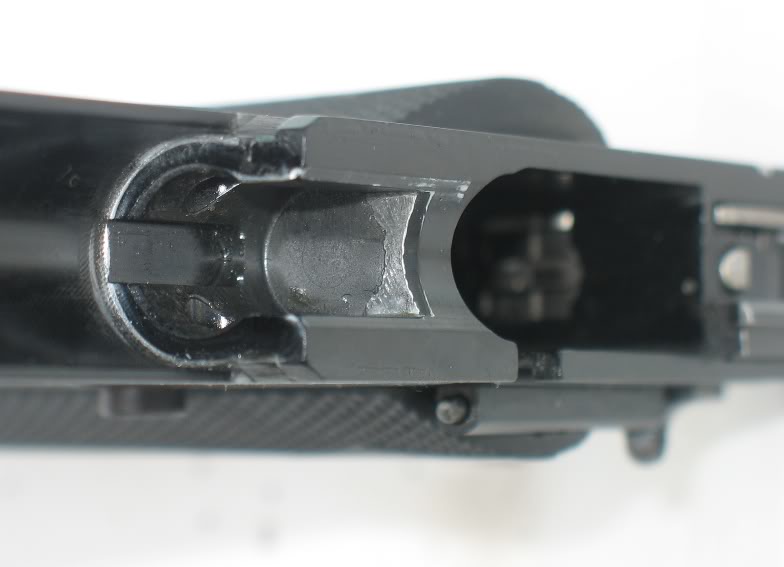
Distributed VIS contact (Springfield TRP)
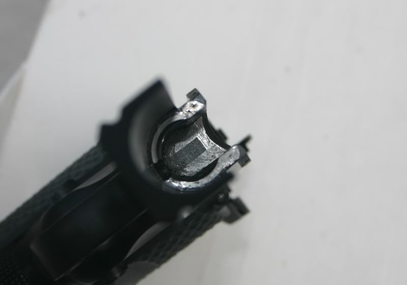
Another distributed VIS contact (my home built 1911)
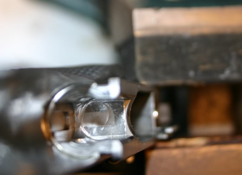
Now the contact marks from the Remsport frame that I am using to build this pistol:
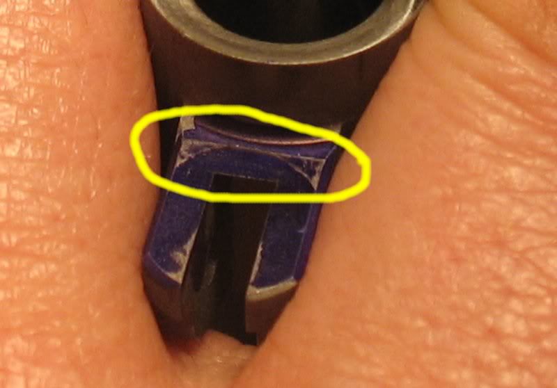
Remsport frame VIS:
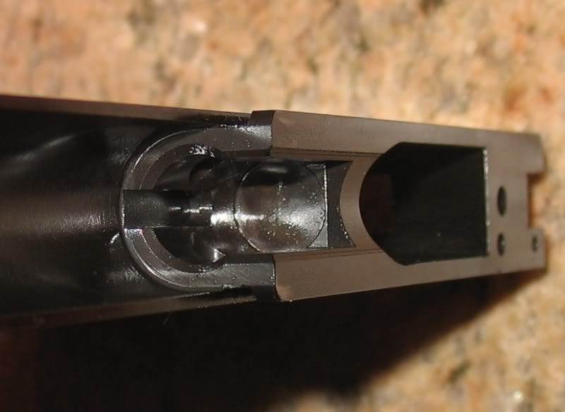
I decided to remove the small bow-tie VIS because it was so small. I also remove material from the lower knees like this Schuemann barrel:
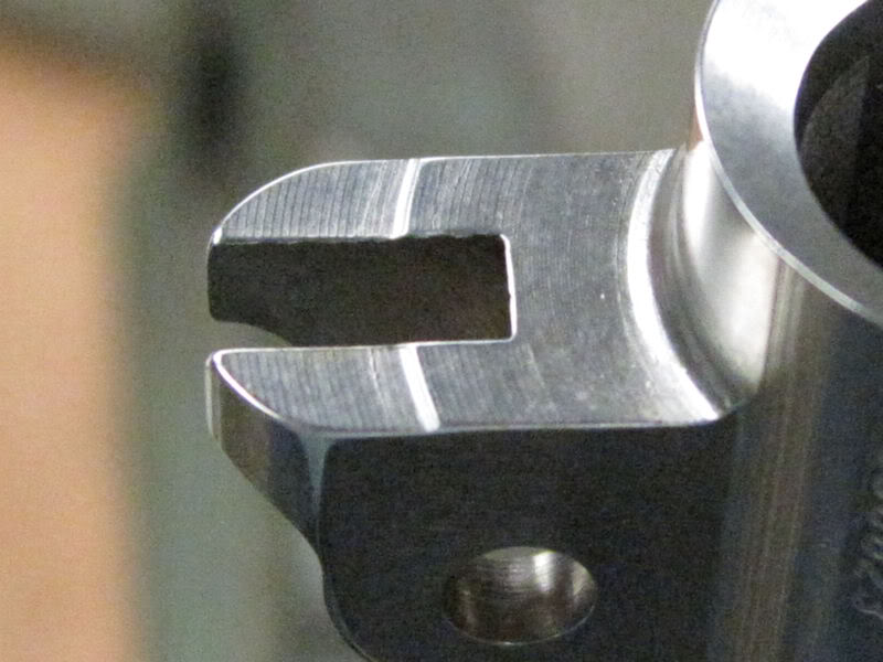
I will report how well this works.
Okay.
Is it stopping on the VIS or the barrel bed?
Quote:
http://www.rodgerspistolsmithing.com/
I read through the write-up you mentioned above. Thank you again.
You may have mis-understood what Bob Rogers was explaining or I mis- understood him.
He fixed a 1911 that the lower (tips) of the barrel knees where hitting the VIS as I outlined in one of his pictures here:
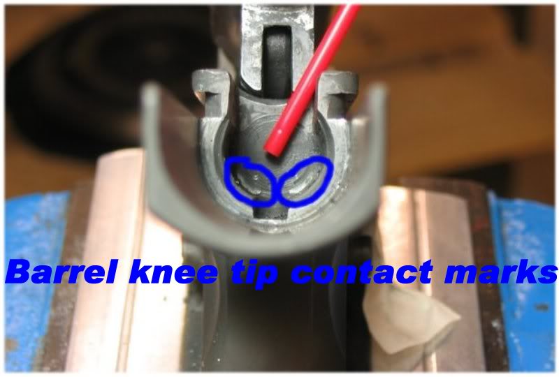
He fixed this problem by end-milling in to the VIS to make a bow-tie cut.
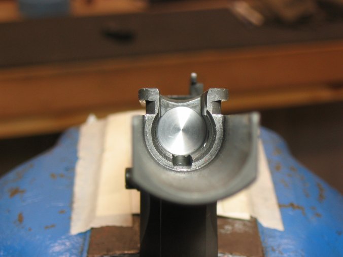
I always watch out for this in all my 1911s. I mitigated this risk by removing material from the lower legs of my Bar-Sto barrel as shown here:
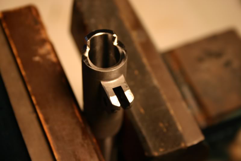
I have not fit the barrel yet so I can tell you if the barrel hits the bed before the VIS yet. I will lower the barrel bed if this happens.
We (this forum) have discussed the advantages and disadgantages of a Bow-Tie VIS many times in the past. There are pros and cons to a Bow-Tie cut. In an effort to help some of the newer readers out there I coppied a great explanation on the weakness of a Bow-Tie VIS cut written by our very own 1911Tuner.
His words are appear on this old topic about link fitting http://forum.m1911.org/showthread.p...40&page=1&pp=1
And are as follows:
"The issue that I have with it is that it leaves a very narrow strip of material at the top of the VIS..where it takes the full impact of the barrel... and it deforms quickly under hard use, until eventually, the VIS is too far rearward.
The barrel starts to stop on the link. The link stretches and effectively lengthens to the point that it's too long to vertically disengage the barrel from the slide at the right time. Or... it reaches the breaking point and lets go, and the barrel can't disengage, and the upper and lower lugs both receive the full impact of the slide. One or two such crashes almost guarantee a sheared upper lug or cracked lower lug within a few thousand rounds... or even a few hundred, depending on the barrel steel. Less likely, but also possible is a cracked slide at the first lug adjacent to the ejection port."
This philosophy together with the fact the Bow-Tie cut on my Remsport was very thin made me decide to remove the raised Bow-Tie section of my VIS.
Good news:
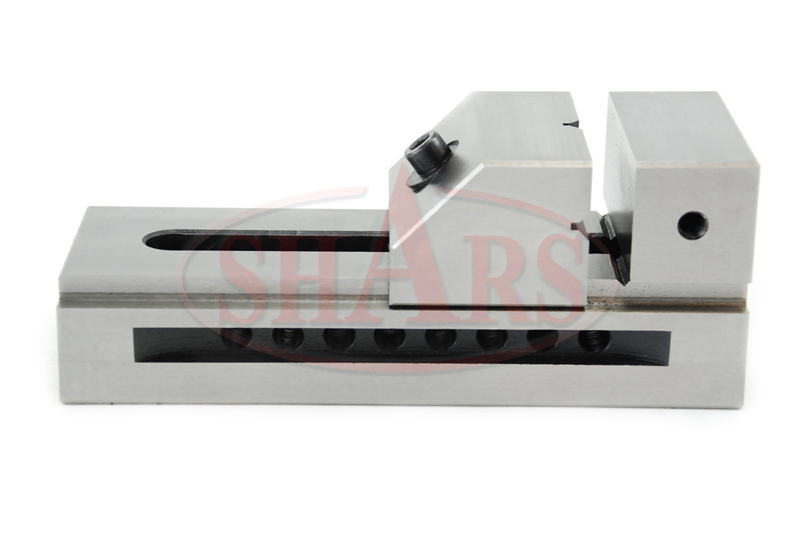
I just bought this toolmaker's vise to help me measure and work on whatever
slide I choose.
Quote:
Great idea.....the 1911 doesn't have main bearings but it should work
great
You can use it to measure locking lug engagement, too.
Got the vise to today.
I may use it to help trim the barrel hood to length and keep the work square to the bore like this:
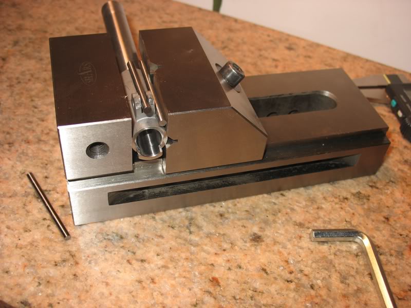
Just an idea... but need a slide that is square too.
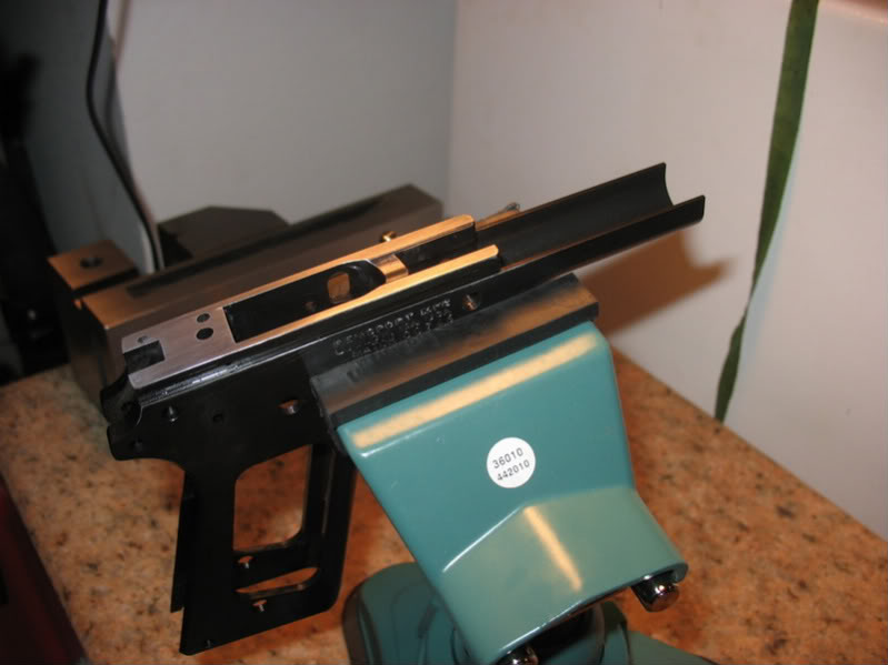
I decided to deburr and polish my frame....I know....I should wait for the slide but the burrs were big and the machine marks deep...
This week's activities:
I ordered a Caspian slide and it should have a 3-8 week lead time.
Rear vertical serrations only, Bo-Mar rear cut, Novak front cut and no logo.
QTY ITEM DESCRIPTION COST EST Total
1 SL45GM 5" .45acp Government Length Slide, 4340 High Carbon Steel
1 CLASSICVERT Classic Style Vertical Serrations.
1 BMR Bomar/Caspian Style Adjustable Rear Sight
1 NVKF Novak Front Dovetail .330x65x.075
1 NOLOGO Leave off Caspian Logos from Slide
I just got a Power Custom frame holding fixture that will allow me to better fit the slide to the frame or vice-a versa.
Installed some temporary grip screw bushings to try her out:
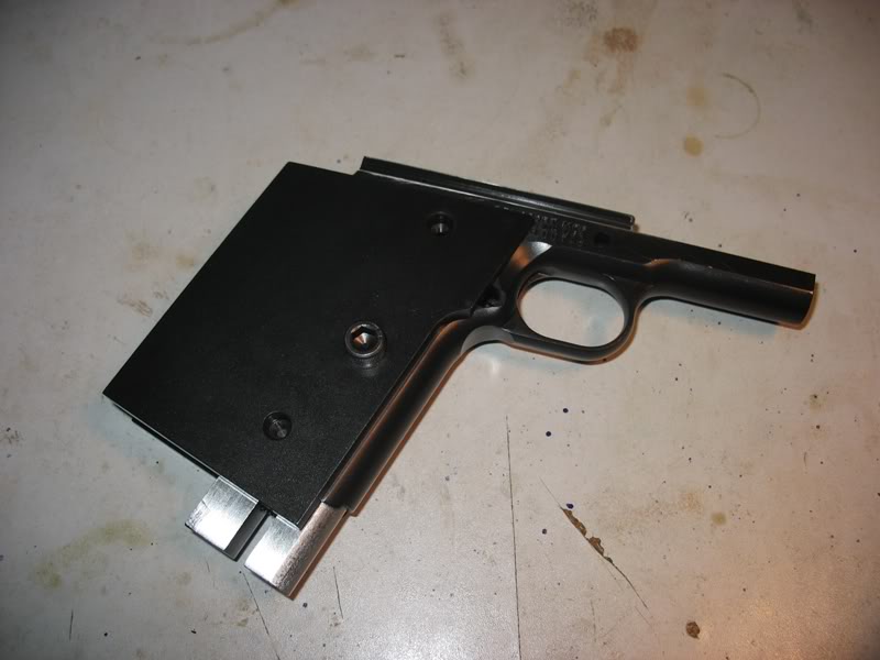
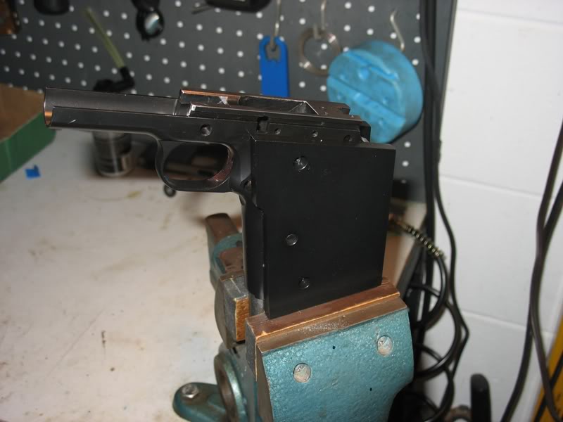
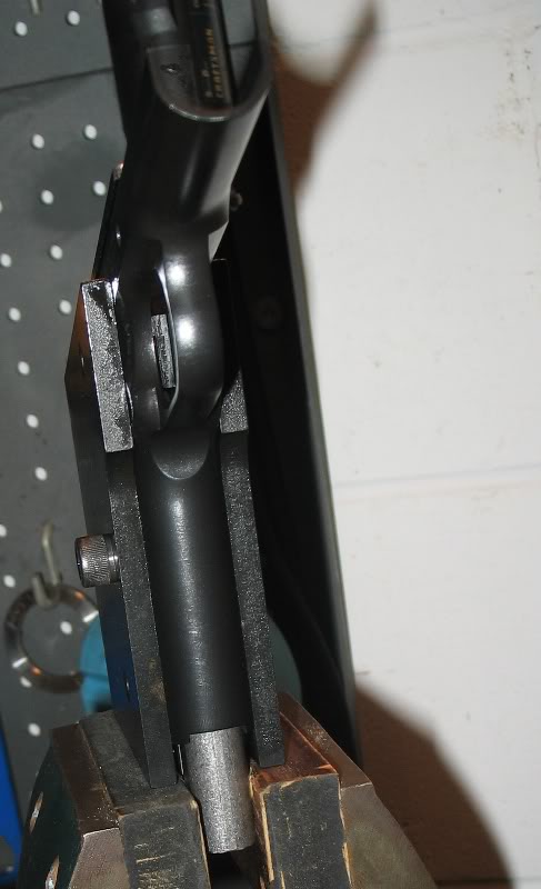
Great Eric! Now, while you're waiting for the slide and the frame's all chucked up, get started on the frontstrap checkering. Idle hands are the devils' playground.
Quote:
Now, while you're waiting for the slide and the frame's all chucked up, get
started on the frontstrap checkering.
Yea but I don't like checkering that extends around the front strap rounds because it makes changing my grip harder.
I really want this:

Or this
I don't know how to serrate my front strap?
Quote:
A checkering file and a lot of patience.
Thanks.
I was thinking about that too... the Colt serrations measure 8@.350 inches = 22 per inch.
Perhaps I can buy a 25 LPI checkering file from Brownells and grind off some to only allow 8 serrations.
You won't have to grind any off, as the curve of the front strap will limit how many are in contact with the front strap at any one time. What you will have to do is make some careful measurements in order to get the pattern properly centered.
The other thing is that you won't be able to get serrations made files to have that nice pointed termination at the top. That is accomplished with some kind of cutter. You'll have to get it as even as you can by hand and then undercut the trigger guard to make it look clean.
Rob is right, it's not an easy task to accomplish by hand.
Quote:
The other thing is that you won't be able to get serrations made files to
have that nice pointed termination at the top. That is accomplished with some
kind of cutter. You'll have to get it as even as you can by hand and then
undercut the trigger guard to make it look clean.
This all make a lot of sense... thanks... the Colt serration depths are equal... which will be challenging with a flat file.
I was hoping to use my new fixture along with a spacer block of some sort to align the work to the front strap... thinking more about trying this?
You don't bring the serrations to full depth with the checkering file; the angle is too steep and it will result in overly deep cuts. You just lay out the pattern with shallow cuts (rotating the file as necessary to account for the curve) and then use a needle file to go to full depth, slowly. For this job, you should use a "bent needle file" from Brownells (or a riffler, which jewelery making places sell).
You might consider practicing on a piece of steel from Brownells or Onlinemetals.com.
I also recommend a magnifying headband and and appointment with your shrink for afterwards.
Quote:
Shame on you for posting about all your cool new parts and tools! Does your
shrink want start a support group?
Sorry... here is a sneak-peak at next week...
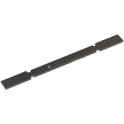
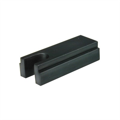
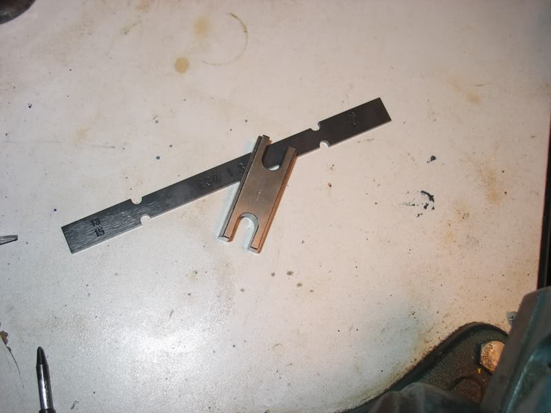
As I promised... here are pics of this week's tooling: An EGW lug-to-breechface barrel hood length gage and a Brownell's barrel alignment block... all in preparation for my Caspian slide order...
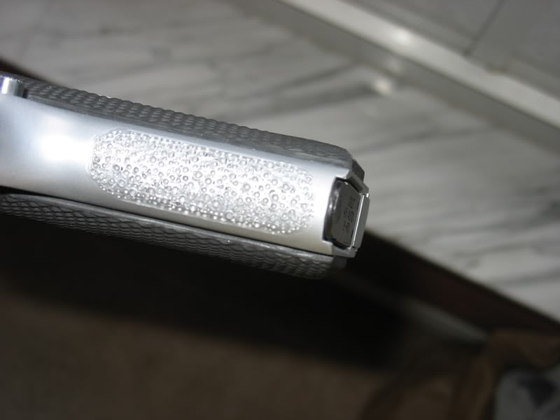
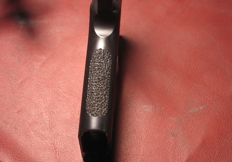
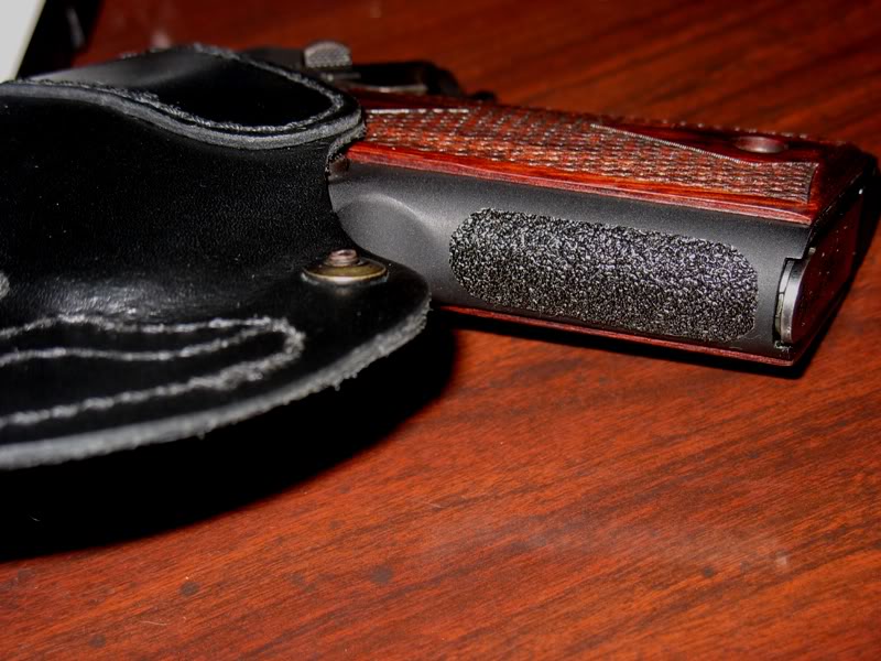
I decided not to attempt to serrate the front strap. I choose to "race track" stipple it like my MetroArms custom home built pistol.
Here is the starting border...
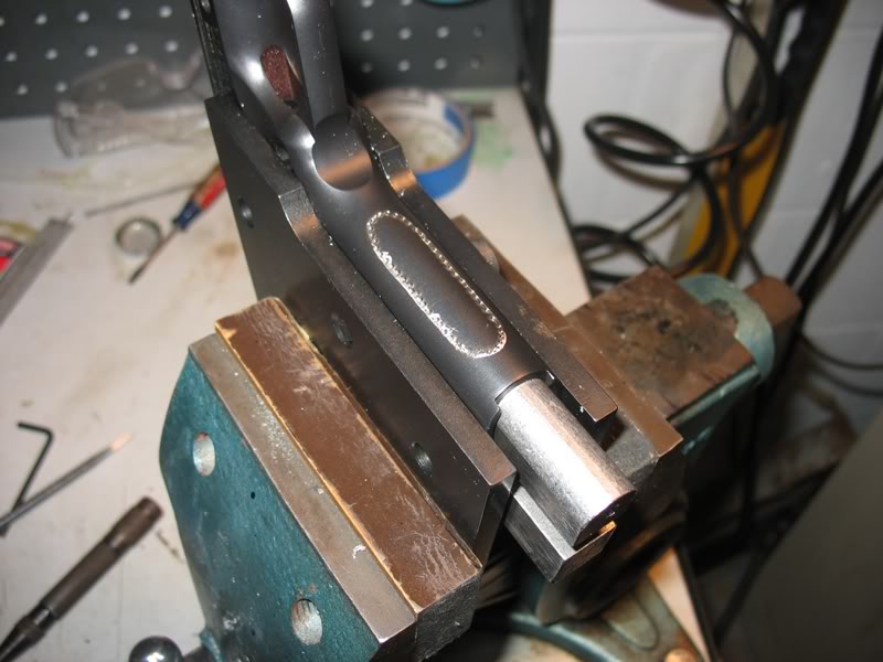
I like the feel of the stippling in the center only.
Quote:
I like the looks of that jig Eric! Are you satisfied with it... I see
Weigland makes one too?
Hello and yes I like the Power Custom fixture. I am happy I have it and can't wait to get my new slide to start beating away This is turning out to be one of those "how did I ever work without this before" purchases...
Here is my first pass at the race track stipple job...
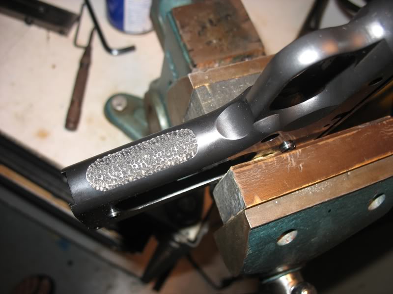
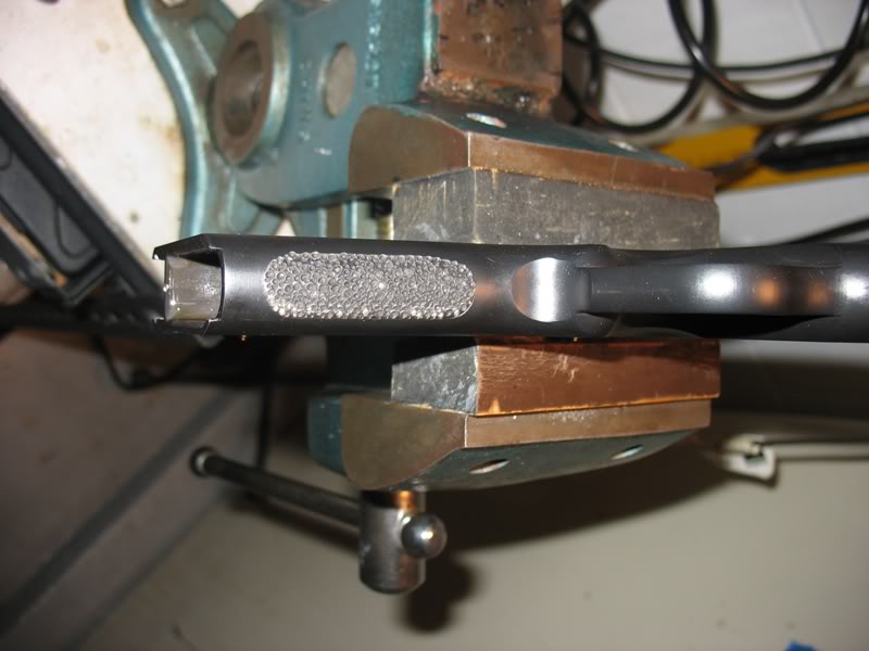
DONE... for now.
Quote:
That stippling looks great! I think I see an automatic center punch in
one of your photos - is that what you use to stipple?
Thanks, yes, I only used my 30-year-old center punch that has set unused for a long time... I think she likes being used again so she did a great job moving metal around.
Quote:
That looks great! That's a little more aggressive then your ACII isn't
it?
Do you think there is any danger of deforming the front strap without using that jig to support it... assuming I only use the automatic center punch? You didn't see any problems caused when you did your ACII right?
Thanks, good eye and good memory... yep... I did this same work to my ACII... somehow the work is easier the second time...
I tried to duplicate the feel of grip tape centered on the front strap because I like this best:
This week is slow because I am waiting for the slide..
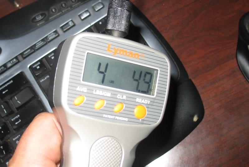
I did get a Layman trigger pull gauge....that I hope to use to help set-up the sear spring when I do the trigger work.
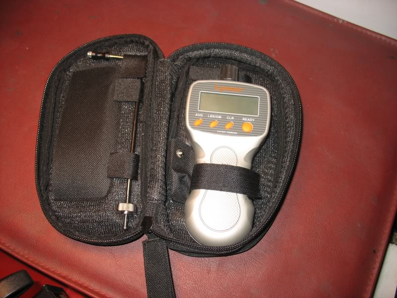
The good news is that I set-up the trigger on my home build MetroArms for a 4- lb trigger using a fish scale I bought at Wal-Mart and measured 4lb 6oz with the "good" digital pull gauge....
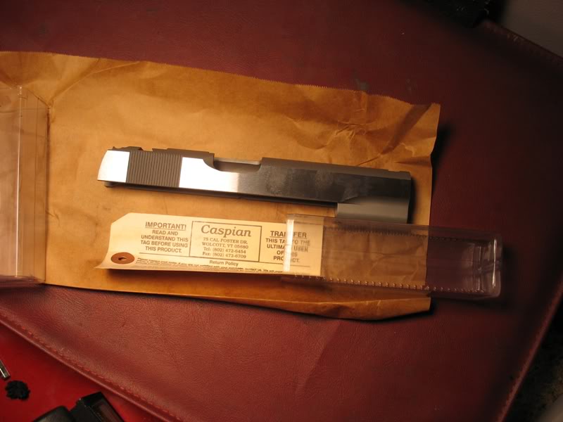
I got the slide today... this was a nice surprise... I thought that Caspian shipped it yesterday but there was a knock on my door earlier with a package from Caspian.
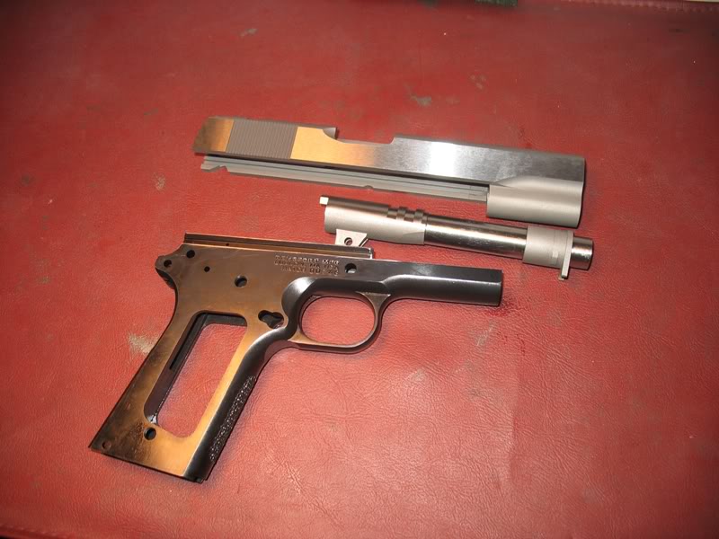
Here is the slide as ordered:
So far I have:
Caspian slide
Bar-Sto barrel
RemSport Frame
Took some measurements
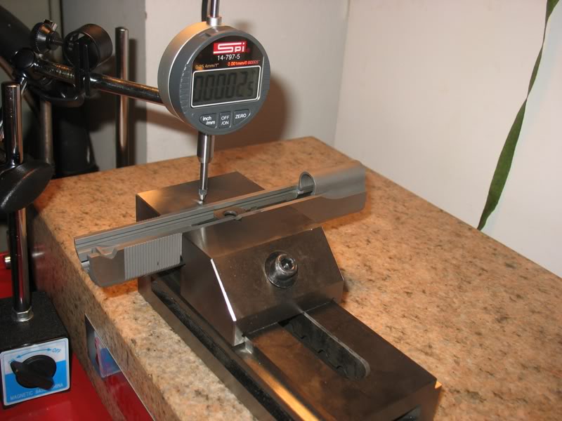
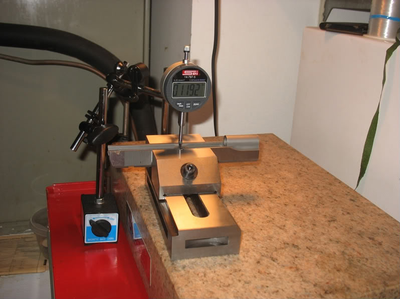
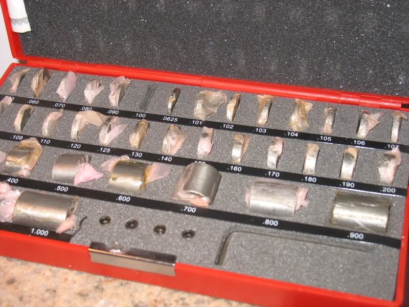
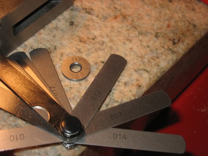
Got the results:
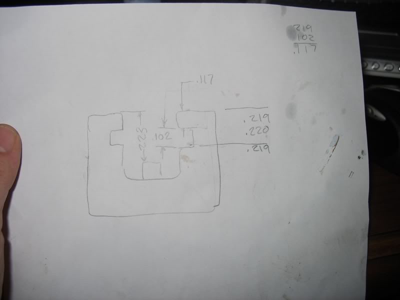
Compare the slide measurements to the frame measurements:

Removed some material from the top of the frame and was able to beat the slide onto the frame with a rubber mallet:
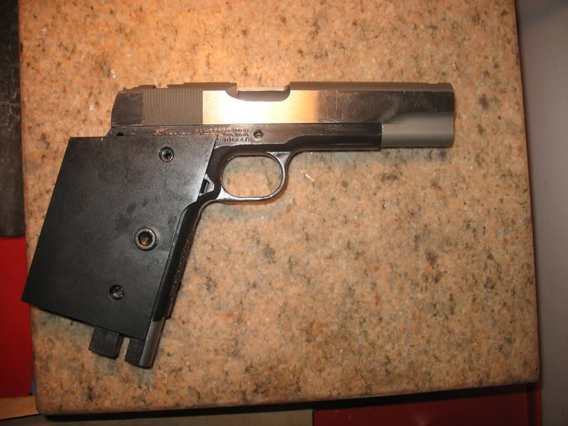
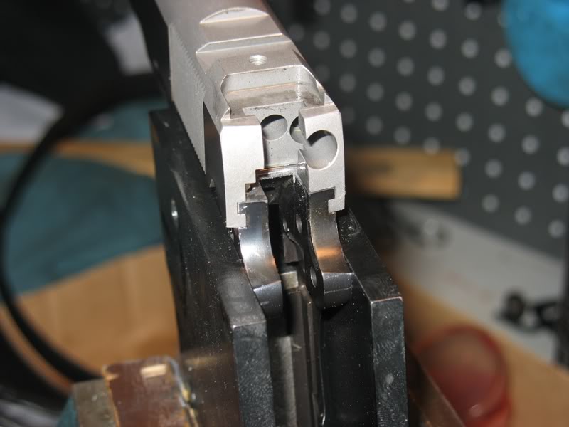
Don't worry... I got if off too... no problem...
Now I am waiting for some lapping compound I ordered:
Wheeler Engineering Lapping Compound Kit (1 oz each of 220, 320, 600 Grit Compound)
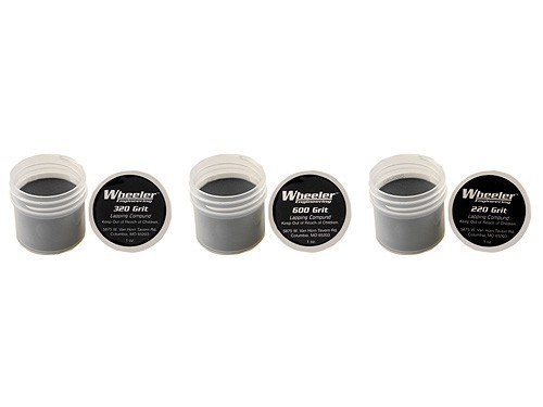
WAIT!
If you are going to use the slide and frame simultaneously to lap each other, make sure the lapping compound you use is a non-embedding type. Otherwise, as I understand it, the compound will become embedded in both the frame and the slide and continue their lapping actions - because once embedded (and making a lap out of both the frame and slide) the compound cannot be un-embedded. This is mentioned in passing on the Wheeler website (next-to-last paragraph) http://www.battenfeldtechnologies.c...apping-compound and discussed a little more here: http://www.us-products.com/sitehtml/lapping.html
Don't know if the Wheeler lapping compounds are the embedding or non- embedding type, but I'd hate to see you turn your project into a perpetual lap - getting lapped a little more every time it's fired.
Edit: "J-B Non-Embedding Bore Cleaning Compound" from Brownells might be a safer choice http://www.brownells.com/.aspx/pid=...EANING_COMPOUND
I will check into the Wheeler compound as I had the impression that it was specifically made to lap frame-to-slide fits.
All I could find on the Wheeler website was their bore lapping compound kit, where a lead bullet is loaded with the lapping compound by rolling the bullet in it. The bullet's then loaded into ammunition and fired and the lap (bullet) ends up in the dirt somewhere.
I've not done much lapping, but do recall that the lap material must be softer than the material being lapped, e.g., the traditional bore lap is a series of leather washers on the end of a rod. If the lap is harder than the material being lapped, the abrasive particles initially embedded in the lap might get transferred to and embedded into the material being lapped.
But if the lap and the material being lapped are about equally hard, I'm not really sure what happens - except it might not be too good. Maybe it's all OK. Maybe some other Forum member really knows!
Thanks again... yep, the lapping kit I bought is for barrel bores ... perhaps I will just use the Aluminum Oxide lapping compound that Brownell's recommends here:
http://www.brownells.com/.aspx/pid=...PPING_COMPOUNDS
Brownells states: "Aluminum oxide crystals are smooth and rounded in shape, so they won't embed and continue to wear the part after cleanup."
Good thing you noticed what I bought... and I am in no hurry.
Hello again and off to new measurements:
I like to measure
I used a tool-thing-fixture-barrel-hack-I-made to measure my slide lug spacing:
Fourth on bottom from left to right...
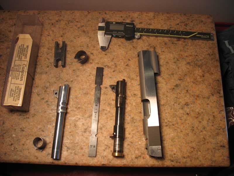
Like this:
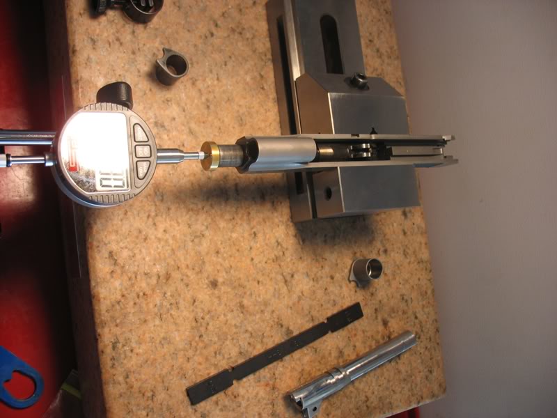
And compared the measurements to the Bar-Sto barrel.
I measured the slide to be:
No-1-lug to No-2-lug = .331
No-2-lug to No-3-lug = .328
I measured the barrel to be:
No-1-lug to No-2-lug = .320
No-2-lug to No-3-lug = .325
This means that I have to move the barrel's No-1 lug back a whopping-colossal .011 to get lug-1 and lug-2 contact and within .003 for lug-3 contact...
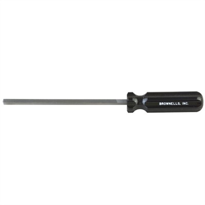
I don't know if I can pull this off with my Brownells hammer squaring file or not:
Plus... the slide No-1 to breechface measured at 1.315 with the barrel-no-1 to hood measuring in at 1.322... this only gives me .007 to play with.
Can't tell from the pics, but to measure the slide the dimension of the rear facing lug face to the next rear facing lug face. And the barrel would then be from the forward facing lug face to the next forward facing lug face.
Might re-check, easy with a height gauge.
Hello Jon and thanks for the suggestion...
I don't own a height gauge but there are some at my work...
I decided to make this tool to measure slide lug spacing...
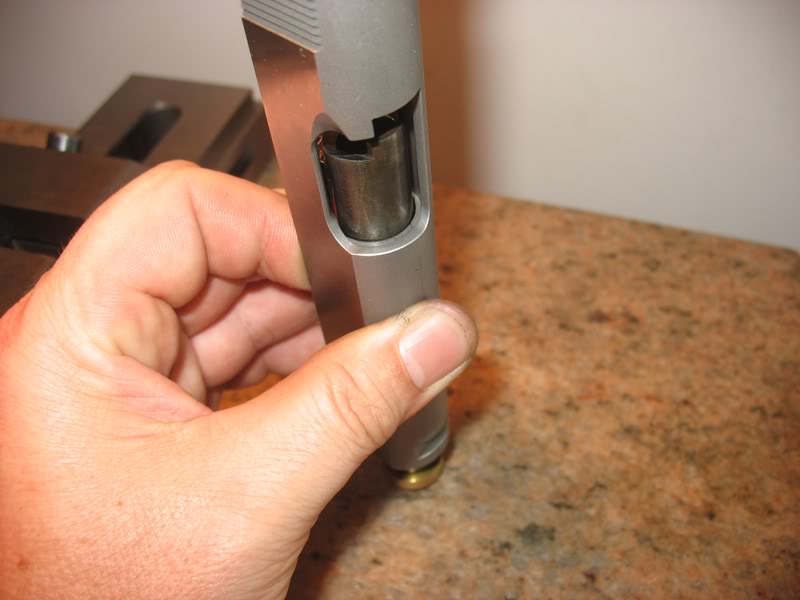
It is a barrel that I removed all but the center of the first lug and dropped the hood diameter down so it can ratchet from slide lug to slide lug like this:
Tool:
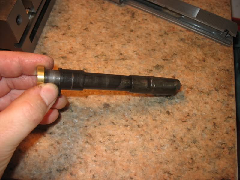
Installed forward on no-1 lug:
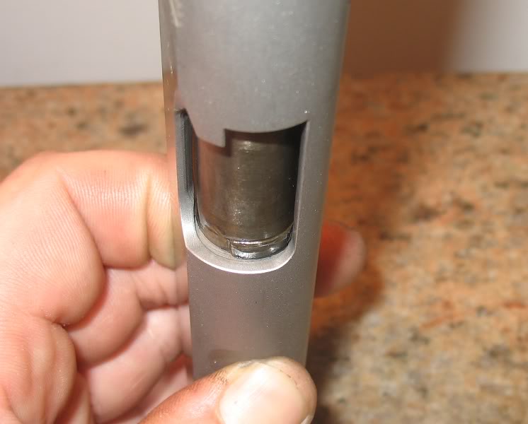
Forward on no-2 lug:
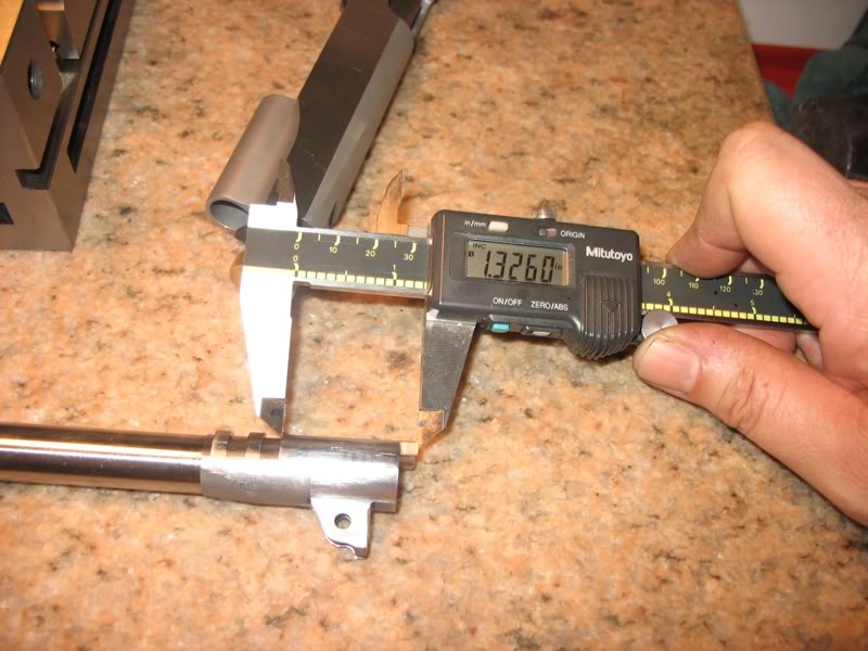
How I measured the barrel lugs:
I already fit the barrel hood width leaving .002-.003 overall side clearance but won't fit the hood length until I figure this out.
My inexperience with Bar-Sto barrels leads me to believe that perhaps Bar-Sto intentionally left the No-1 lug too far forward so a smith can fit to many different slide... just a guess... don't know.
That was understood, but in each photo the barrel lug's rear face would be bearing on the slides forward face and it's the opposite face to face you want to measure. In the pic with the indicator on the barrel muzzle end the indicator plunger which is spring loaded is pushing the barrel back. Perhaps a spring that fit in the chamber and pushed the barrel forward in the slide would help.
The items you have for measuring are good, but the set-ups are odd, and leave room for doubt.
Quote:
That was understood, but... the set-ups are odd, and leave room for
doubt.
I'm with you... me too... this why I measure and measure... I checked the slide with a feeler gage and calipers like this:
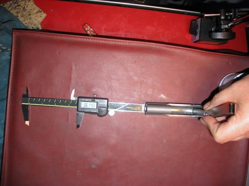
These measurements match the indicator within .001...
I successfully moved the No-1 lug back on my Bar-Sto barrel about .010 and here is how they measure now:
slide (indicator);slide (calipers);Barrel (calipers)
lug 1-2;0.331;0.330;0.330
lug 2-3;0.328;0.327;0.325
So I should hit No-1 and No-2 lug OK with No-3 following .003 later...
The bad news is that I botched the hood length... it is .005 too short...
I will take the barrel to work to have a welder TIG the end of the hood so I can re-cut the length.
I finished fitting my frame to slide fit... she is very tight but will slide under her own height at about a 15deg angle...

Finished assembly so far....
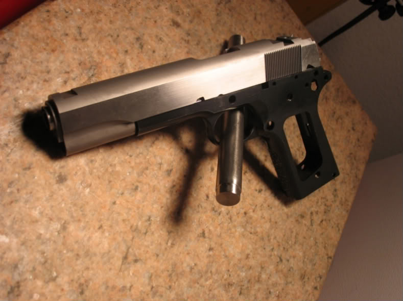
I welded the hood of my Bar-Sto barrel and re-cut it... Now I have .003 total side clearance and .0005-to-.001 end-play
Need to figure out how to fit the lower lugs without spending the $180 for the lug cutting kit... OR?... don't know.
Remember that this is all a learning process.
Quote:
for every task, there is a proper tool. There can be substitutes, but
seldom are they as effective as the proper tool.
Yep... I know that I have to buy a lug cutter but I am still in the denial phase of owning up to what's ahead... so far I have made it on blood, sweat and tears... Oh yeah, luck too.
Thanks for the nudge... I am officially leaving denial.
I know a smith that does it with a file.
I used a 3/16" round chainsaw file and draw-filed the lower lugs on my first NM barrel for a tight lockup. The file was rotated "into" the cut while drawing it along the lugs. It was an agonizingly slow process, but an ounce of skill and a ton of luck got it done.
This was done in about 1965 or 1966, and I don't know if lug cutters were available back then.
I know a 'smith that does it on a CNC mill. The lug cutter would seem to be a reasonable compromise.
If you have access to a welder, why not buy a cheap Sarco barrel, weld up the lugs a bit, and practice fitting that before hacking on the Bar-Sto?
I learned checkering on a bit of steel rod before I attacked a frame with it.
Here is an idea!
I will choose a Colt thumb safety similar to this one:
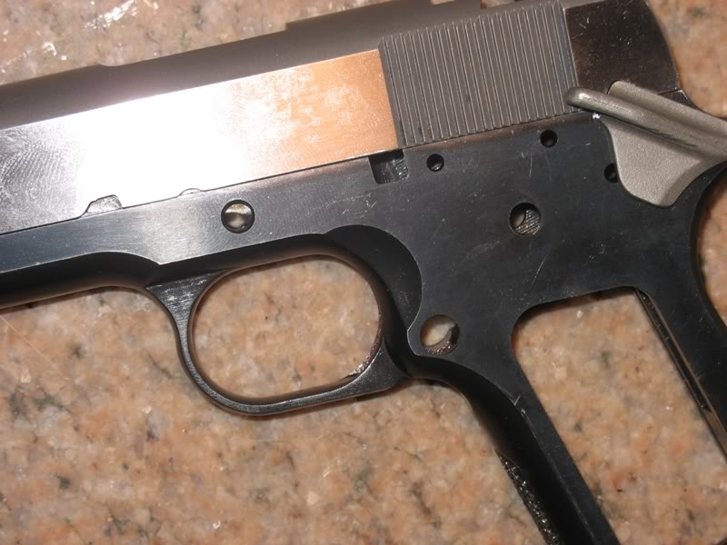
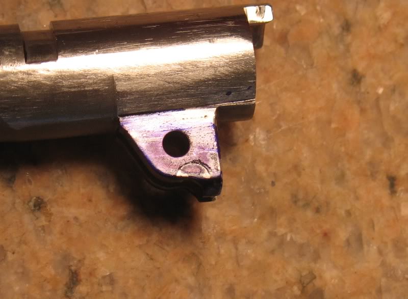
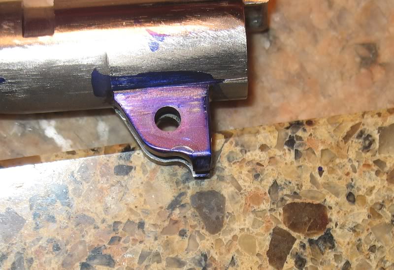
And the barrel lug overlaps the SS hole like this:
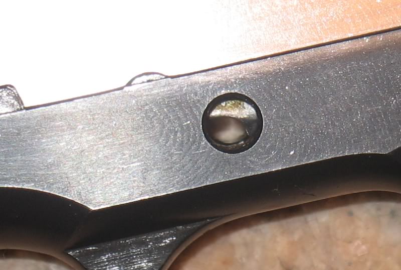
Dycem blue the lugs and work a .200 gauge pin in the SS hole:
Clearly see how the slide stop pin in ride relative to the lugs:
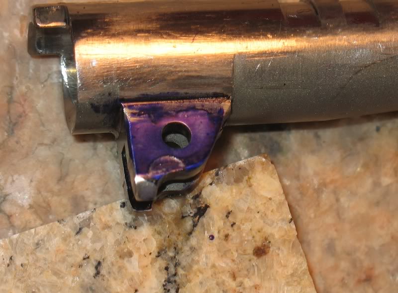
Remove a smaller diameter .195-.00? offset around the pin location to give a fit like this:
 egumpher
1st April 2011
Perhaps I didn't allow the barrel to fully lockup...I will do it again with a loose bushing to see how the pin hits...
Redo...
Thank you Niemi...
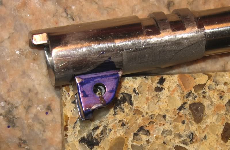
I never said that I fit the Bar-Sto bushing yet...
A loose bushing does wonders...
Those latest photos look about right vertically and here's the method I use to keep the barrel shoved all the way up into the slide:
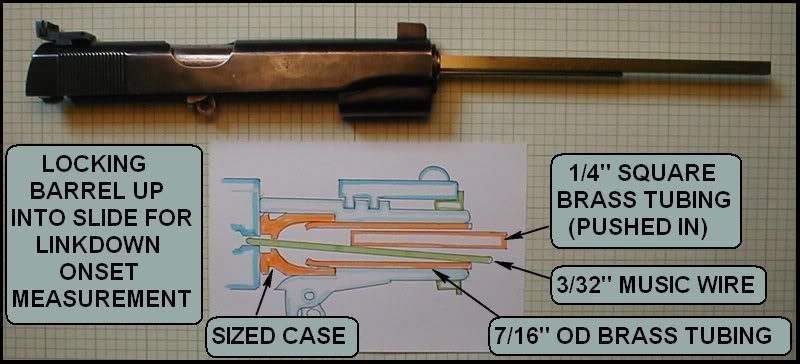
I have read different approaches/methods to cut lugs from a .100 rear lug thickness, to until the thumb safety engages properly to until the frame and slide align.
JK Vol-1 pg 128 states ""When the back of the slide is exactly even with the back of the frame, the lug is fully cut".
Brownell's series "Building a 1911" states:
"Be careful you don't cut too far and take metal off the back of the lugs. You should cut enough metal to allow the thumb safety to go into engagement"
Don't know which is correct?
There's a third criterion: the disconnector centered in the disconnector cut in the bottom of the slide. The thumb safety also must be able to enter its cut in the slide, which, of course, locks the slide in place.
The one criterion that is not valid is the slide fitting flush to the frame. That's irrelevant, and in some cases, will lead to overcut lugs. Some slides are made a little "fat" in the back so that the craftsman can blend the frame and slide perfectly.
Be careful re: JK. We use his book(s) as a reference only, because it's more convenient than the prints when we need to check a dimension.
The JK statement is predicated on a correctly mated slide and frame, basing it on the thumb safety is also based on a previously correctly fit barrel. When unmatched parts are used, the bottom line is all about the barrel, and the slide, and frame are controlled be it and it's needs. How they integrate with each other. The back of the slide, and frame alignment will be a result not what dictates how far the lug is cut. Same with the thumb safety. One of these two areas or both may actually line up, but they are not the points to use.
Think about the .100" of slide travel, before the link gets to the point that the barrel begins link down. So the .100" can be divided into fore, and aft. If the barrel is up tight on the slide stop pin when the link pin hole center is past the slide stop pin center by .050", then the barrel will still be in the same position with the slide when the bullet exits as where it started when in battery.
This may seem like a dumb question. When you cut the lower lugs it seems like you would gain barrel lockup? What if any are the other results of cutting the lugs. If the first statement is true then you would also effect firing pin contact on the primer? What are the adverse effects of over cutting the lugs other than firing pin center and too much lockup which results in what? Sorry just trying to wrap my head around this. Thank you for sharing a great information.
This is an oversize barrel so the lugs have to be cut. The upper radial lugs will control how far the barrel can go, and the lower lug cut will control if in fact it does. How far it is cut to the stop surface is an important point to understand.
Thanks Jon, This makes the most sense...
I assume that this is the .050 from link center that you describe.

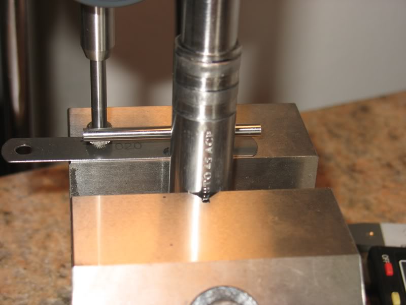
Determined that there is .250 from the back lug VIS to the center of the .155 hole:
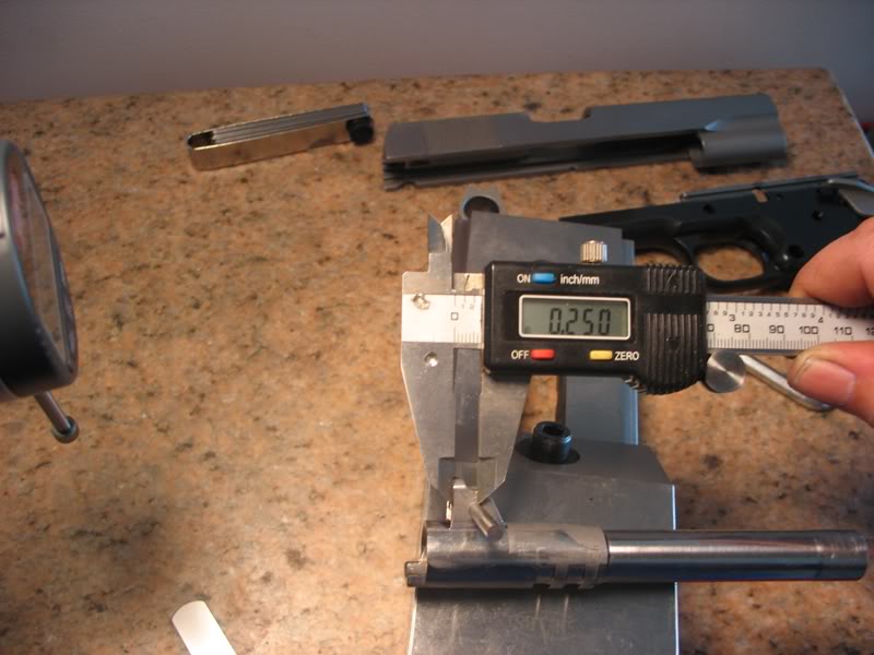
Set a caliper to .250-.050=.200 and scribed marks where the center of the SS- pin should be at lock-up:

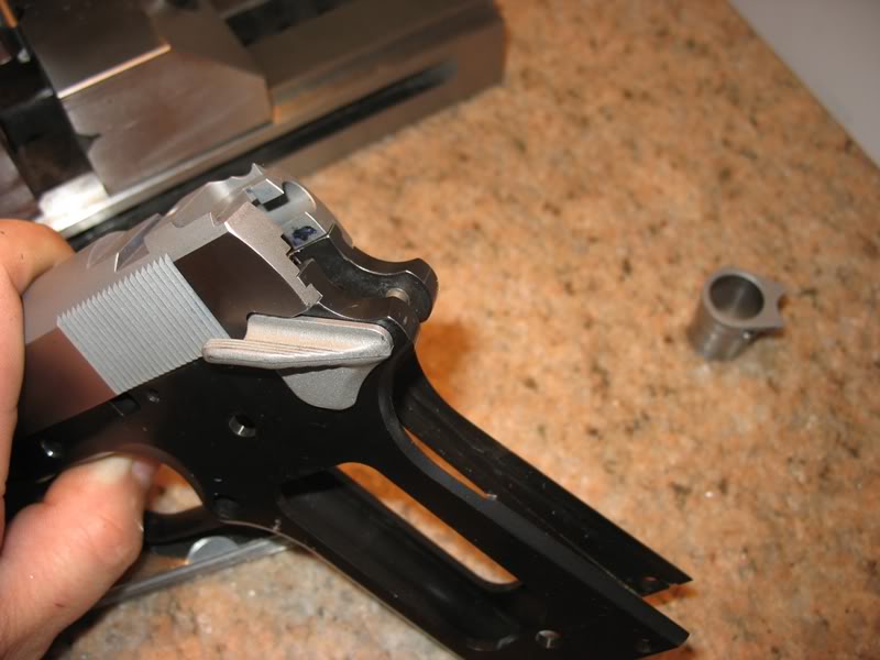
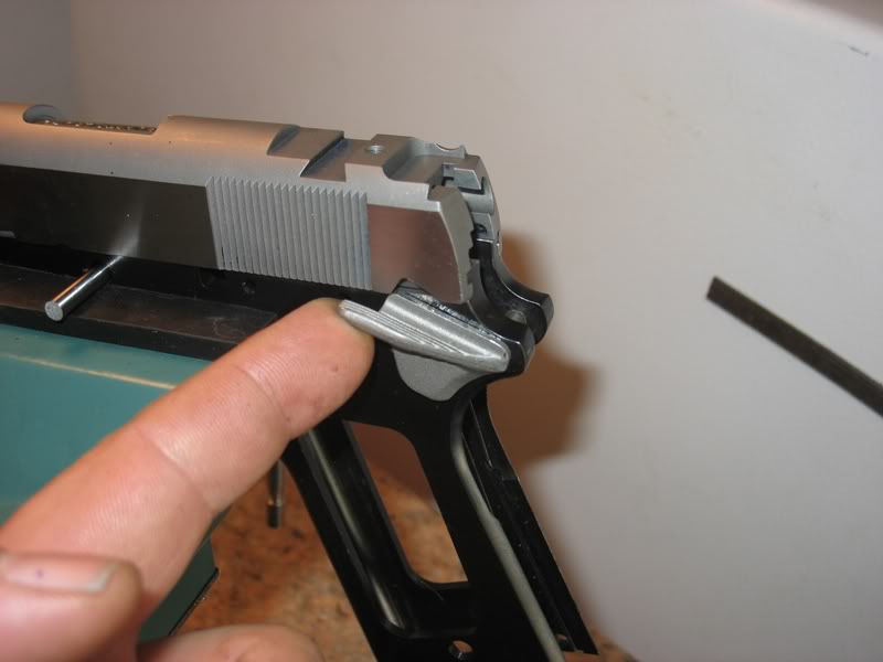
By the way, both the thumb safety and slide-to-frame surfaces line up:
It will be interesting to see where the .050 offset places these parts.
Quote:
It will be interesting to see where the .050 offset places these parts.
Don't be too hasty. My quick and initial calculations (based on the NM barrel data on page 100 of Kuhnhausen's Vol 2) show that offset between pin centers to be 0.04425" - not 0.050". But being quick & initial, I haven't double- checked my arithmetic yet. If about 0.006" makes any difference to you, give me an hour or so to git 'er done!
Don't worry... I am still in the "understanding phase" of this stage of the project. I don't intend to cut anything yet. I haven't event determined if I can try this without a lug cutter or not yet. But at least I understand more about the philosophy of the build.
The good news is that I am the only person who will benifit or regret all of my decisions so far... or at least until I have grandkids who may inherit this some day.
The best I can determine for now is that this is closer to the final position of the slide-to-frame which will require minor fitting of the thumb safety and rework of the backend of the pistol.
Here's what I came up with:
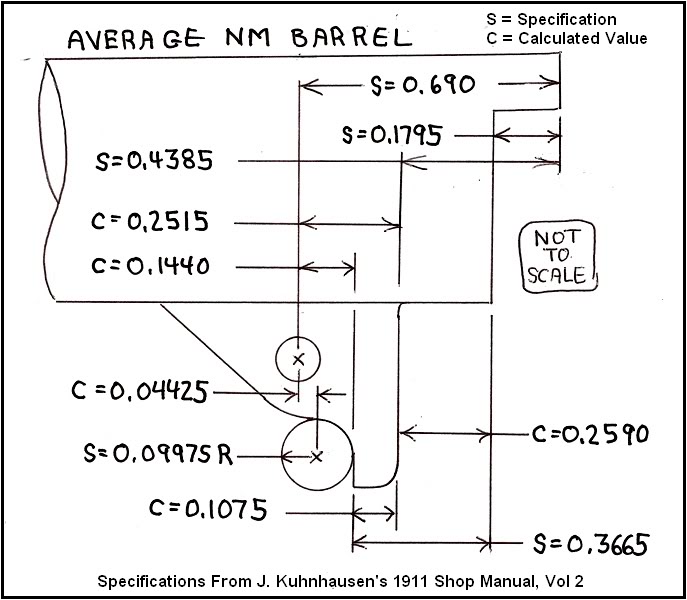
All these horizontal calculations were based on maintaining the 0.1075" lug foot (?) dimension, an average slide stop pin diameter of 0.1995" and the assumption there were no dimensional errors in the Kuhnhausen book.
Even though I've never seen an Army Ordnance blueprint for the NM barrel, I'm pretty confident in those dimensions in J.K.'s book. Have only spotted one dimensional error in it.
Just for comparison, that 0.1075" dimension is 0.112" on a USGI barrel. I vaguely recall seeing a minimum acceptable value for that foot dimension somewhere, but don't remember what it was, who said it or where I saw it. Sheesh!
Well, I looked into cutting by hand but I decided that the risk is too great for a target pistol.....I did attempt to file by hand but wasn't confident with my work.....there is still plenty of metal to left so I choose to finish up with a Brownell's lug cutter......
I found a use for all the original parts I replaced on my other pistols... including those thin-grips I never really liked until now...
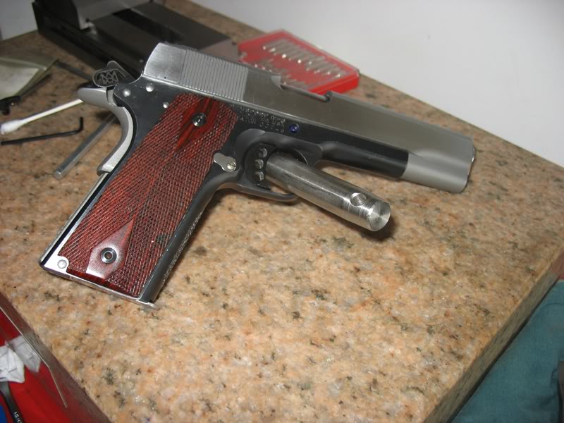
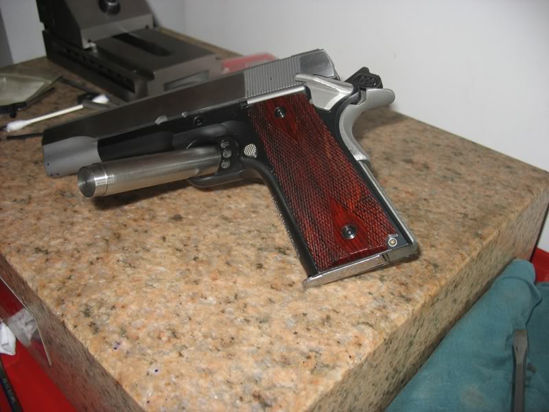
Once I cut the lower lugs I should be good to go the the range to see how she shoots...
Did you get the "kit" $180, or selected components? Wondering if that "pusher" tool is necessary.
I didn't buy the .186 cutter but everything else that includes:
Barrel holder
Handle with .195 cutter
slide pusher
I don't think I needed the .186 cutter because I already filed some lug material off... I think that the holder and pusher should be money well spent.
What's the purpose of the 0.186" diameter cutter? Is it:
* To remove the majority of the excess material so the final fit can all be done by hand (without using the 0.195" diameter cutter)?
* To make it easier for the 0.195" diameter cutter to make the final cut, leaving a lot less material to remove for the final fit?
* To save war & tear on the 0.195" diameter cutter if the 0.195" cutter is always used?
* None of the above?
The .186'' cutter allows you to sneak up on the final cut giving you more to work with when checking contact from left to right. It isn't as small as it would seem as the .186" is centered so it's going to cut the lug shy of a common slide stop pin of .196" by only .005" or less in the realization that the .196" pin lays in the bottom of the frame hole and the .186" cutter is centered based on a .200" hole. This is a value to be able to use a larger slide stop pin at a later time to tighten the fit. But to each his own.
Quote:
shy of a common slide stop pin of .196" by only .005" or less in the
realization that the .196" pin lays in the bottom of the frame hole and the
.186" cutter is centered based on a .200" hole. This is a value to be able to
use a larger slide stop pin at a later time to tighten the fit. But to each
his own.
I thought a SS-pin measured .2005 -.002 or 0.19805 to 0.2005...
I have two new MIM Metroarms SS that measure .1994 and .1999 respectively. I intend to try the .1999 pin for the fit.
Spec and reality are not always the same, so the reason for fitting. Your post states one size in thought, and another in hand. It's the ones in hand that get fit. The smaller pin fitted leaves a larger for later. .200" isn't better if a .196" locks up nice. The .200" can be used later to take up clearance, then that's better. The .195" cutter will cut the lower lug for a .198" pin. The cutter shank that rides in the frame is .200". So this means the lug is cut .0025" less than a .200", per side and we are working on one side. So you can see that the cutters are not so undersized as they may seem by the numbers.
Quote:
The cutter shank that rides in the frame is .200".
Aha! That explains a lot and removes the mystery of the cutter sizes. Learn something new here every day.
I would like to inform everyone that I decided to build this pistol so that I may be used in CMP-National Match Hardball competitions.
I may home Parkerize it or let Fords blue it. I will use Colt WWI controls (like my MetroArms build), a spur hammer, standard grip safety, solid trigger and standard serrated MHS (is a plastic MSH legal?)
More little things arrived...
Colt 1-Piece Recoil Spring Guide
Colt Recoil Spring Plug 1911 Gov
Colt Hammer Strut 1911 Blue
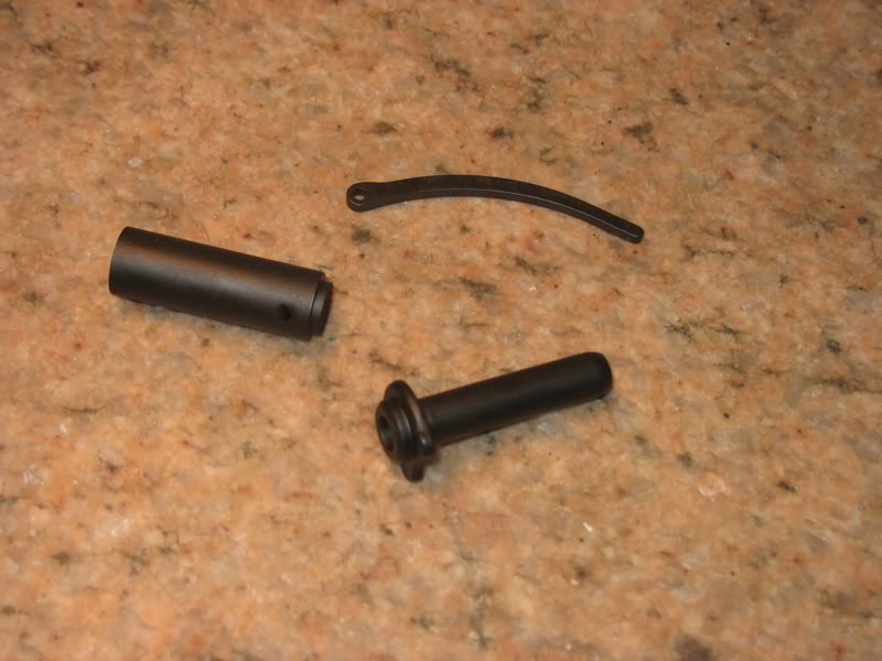
I like the captive spring feature on the return spring plug... got-to-like Colt stuff.
Quote:
Spec and reality are not always the same, so the reason for fitting. Your
post states one size in thought, and another in hand. It's the ones in hand
that get fit. The smaller pin fitted leaves a larger for later. .200" isn't
better if a .196" locks up nice. The .200" can be used later to take up
clearance, then that's better. The .195" cutter will cut the lower lug for a
.198" pin. The cutter shank that rides in the frame is .200". So this means
the lug is cut .0025" less than a .200", per side and we are working on one
side. So you can see that the cutters are not so undersized as they may seem
by the numbers.
Hello Jon and how right you are...
I just finished cutting the lower lugs with a .195 cutter then filed the center of the arc with a 3/16 file to assure that the SS pin would only contact the bottom and back of the lug profile... and it worked... yippee...
The thing is, that I couldn't cycle the pistol with a .199 pin after I was done... I was forced to use the smallest diameter pin I had available, which was an old worn Cold stainless SS that measured at .1985 (lower limit of spec)
The slide wouldn't even close on the.1999 pin I have.
Here is how the lower lugs turned out:
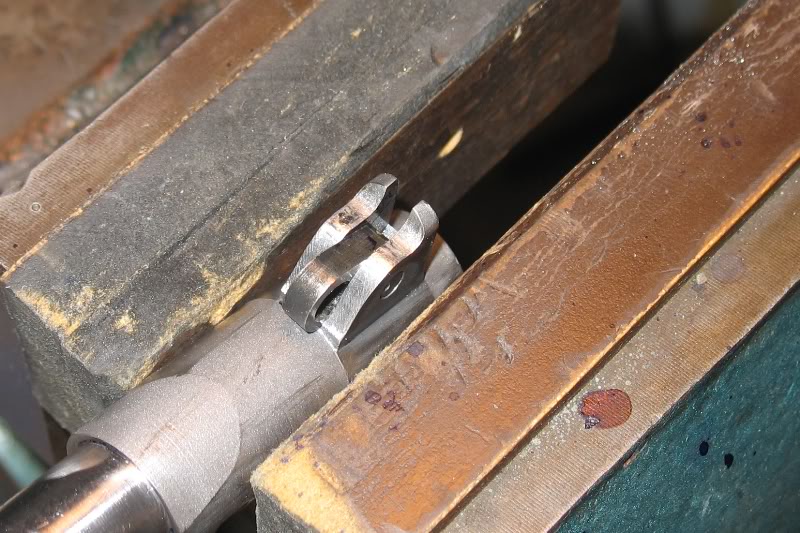
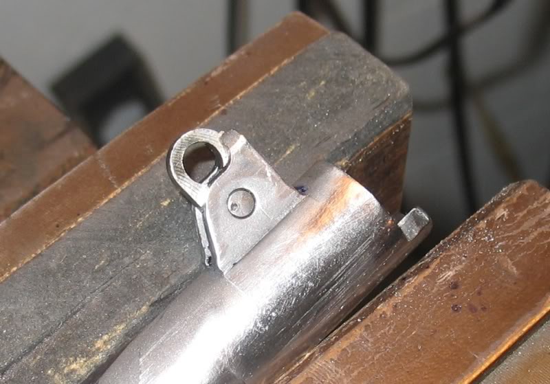
I took some measurements:
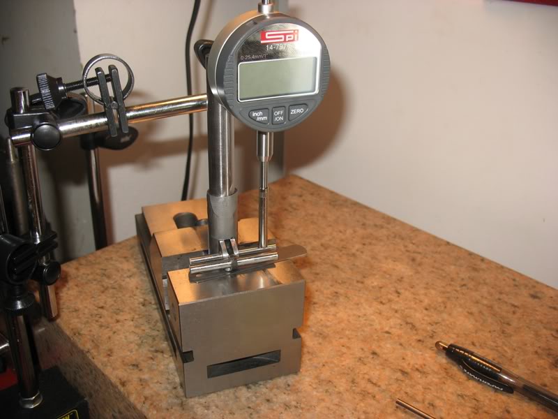
And got these results:
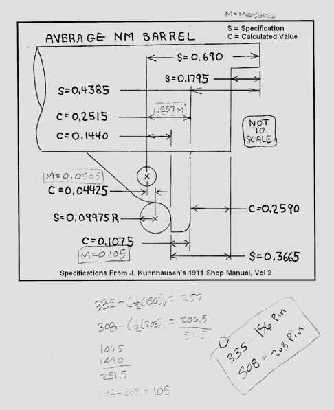
I moved the locking profile back to .050 behind the 155 hole, not on purpose, it just ended up here and is a little farther back than the .04425 Niemi calculated.
I measured .103-ish from the edge of the 155 to the lug profile and started to size a long link but decided to use the Bar-Sto link that was provided because it has an oval shaped pin hole that look like it will work better than a long link.
I did a few timing test... she works great...
Looks good and dimensions are good also. There are two methods about the link, and Bar-Sto subscribes to one of them. Riding the link at all times left out.
That is the idea that the link should do nothing, but tether the barrel to the SS pin, and affect link down, and not have any contact when going to battery, hence the elongated hole. So the top side of the link SS pin hole is always below the lug surface.
The other more popular method is to use an unaltered link that is as close to the SS pin at the bottom when in battery as possible, but not bind, and when the barrel is in link down and begins to be pushed forward by the slide, the top side of the link rides the pin to get the rise to battery started, and then passes off to the lug.
The Bar-Sto method can result in barrel bump developing, but can be smoothed and converted to the other method by substituting a new link with stock hole of correct length. To stay with the first method the cam surface of the lower lug can be lowered so the transition is smoother, at the sacrifice of the longer preferred lug flat.
Quote:
The Bar-Sto method can result in barrel bump developing, but can be
smoothed and converted to the other method by substituting a new link with
stock hole of correct length. To stay with the first method the cam surface of
the lower lug can be lowered so the transition is smoother, at the sacrifice
of the longer preferred lug flat.
I suppose that I will keep the Bar-Sto link for now and if the pin bumps the lug too much I can alway get a .283 link and give it a try...
This week's activities include:
Colt Nylon MSH (Yes, I like them and very inexpensive too)
Springfield extended ejector (very inexpensive)
Standard grip bushings
Colt double diamond panels (Old XSE leftover)
Fit Colt thumb safety to sear/disco combination that worked
Now she is ready to go shoot: (sightless)
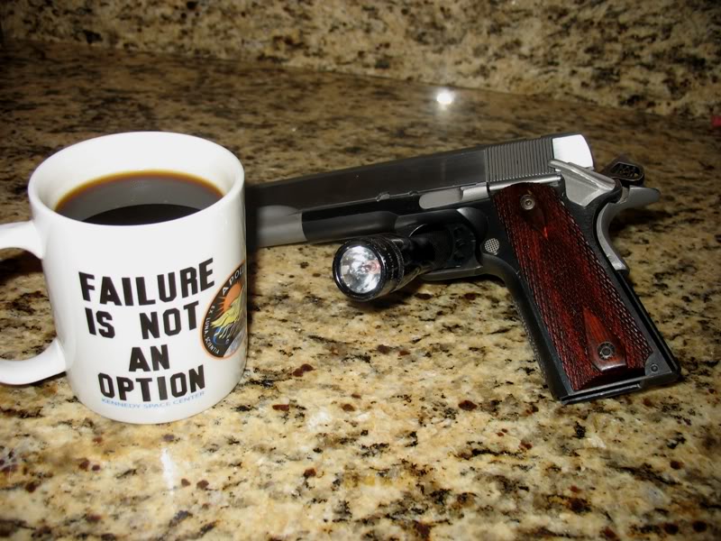
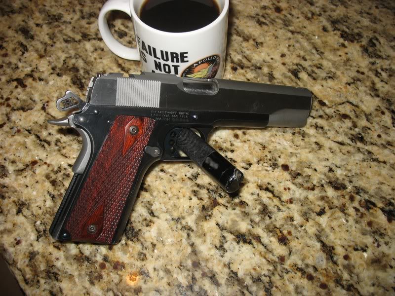
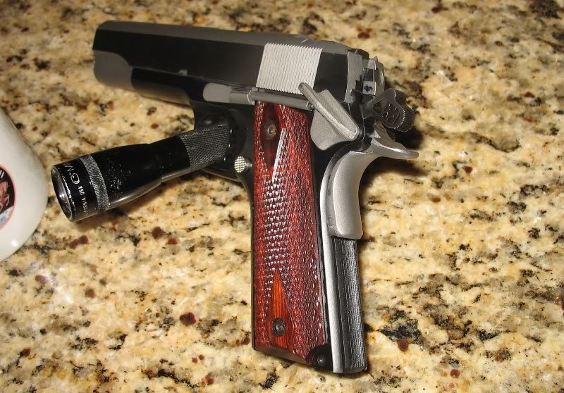
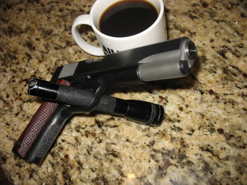
I will try to determine if this pistol is accurate enough to shoot Bullseye competitions before I put sights on her.
Does anyone know someone with a Ransom Rest in the Tampa Florida area I can rent?
If she can't group well enough for Bullseye the I will put sights in here an shoot try Hardball competitions instead.
This decision will determine if I will keep the Colt MSH or replace with a magwell funnel/extension, what trigger group I will use in the future i.e. +4pound or -4pound and optical rail...
Of course, there's always the Pachmyer MSH with that wonderful rubber coating on it. I love mine!
Jeff, I like the Pachmayrs enought that a couple of years ago I bought every one I could find. I had over a dozen. I've used some, but still have some left. Here's one:
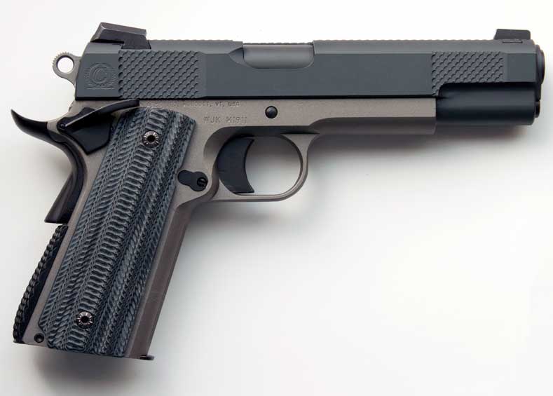
I'm particularly partial to the "C" profile, the intermediate between the flat and arched.
Didn't know there was an 'intermediate', but I've used both flat and arched and love them both. Along with a set of Pachmyer grip panels there is never any tendency for moving around on your grip.
Unfortunately I don't think that Pachmyer grips or MSHs (I own many) qualify for hardball competition. I am trying to keep the initial build as "true to 1911 form" as possible to compete in Hardball competitions and to support this plan I will replace the thumb safety with a Colt WWI and will to replace the grip safety with an original spur hammer design... this is only if the build isn't accurate enough to qualify for "Bullseye" competition though...if it turns out to be a top shooter then I will be able to change components to more modern configuration that can compete in Bullseye competitions... unfortunately Bullseye competition will be much more expensive because I will need to buy optics and a optical rail... I don't know about anything yet so I am planning for hardball...
While optical sights are nice for NRA Conventional Pistol (Bullseye) competition they are not a requirement.
I put 50 flawless round through her as a functional check. Even without sights she grouped very well.
I like to cold blue all the surfaces that I fit to look for wear patterns.
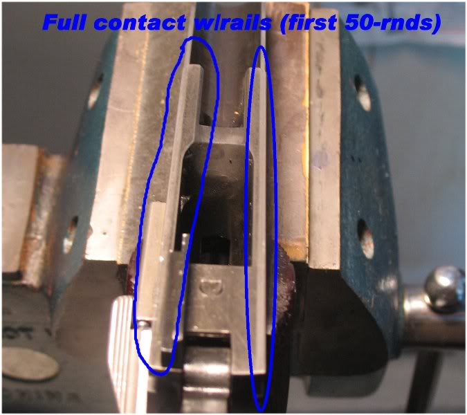
Here are some pictures of the post-shoot inspection (a dirty pistol tells many tales)
Slide to frame fit seems OK... or at least it is more uniform than all my other 45s
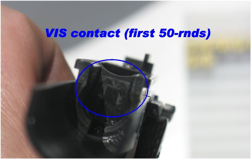
The VIS contact still has a shadow of the Bow-tie cut that was there originally:
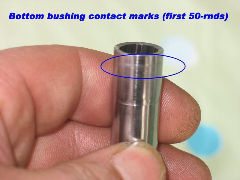
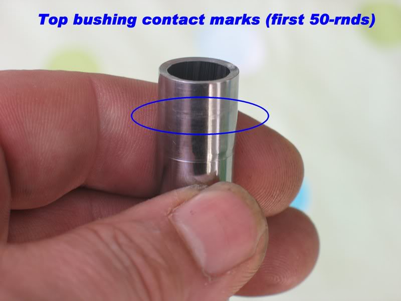
Barrel-n-bushing
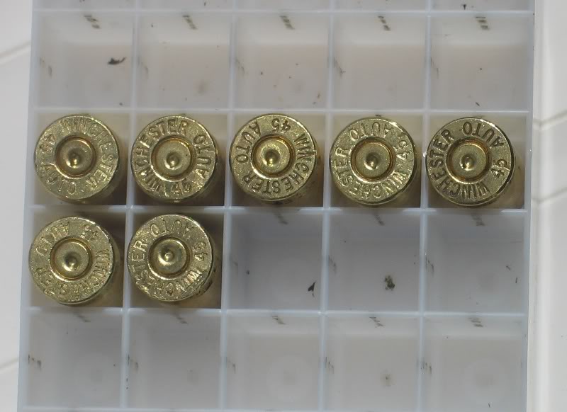
FP strikes with cases oriented up as they were in the chamber:
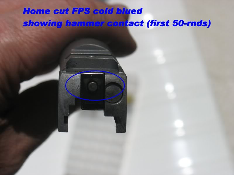
Hammer to FPS contact:
There were no noticable marks on barrel upper lugs unless I really used my imagination.....recall I only shot 50 rounds of WWB...
I broke down and ordered some sights... I choose Ed Brown because I feel that I should get my money's worth rather than choose the least expensive sight out there:
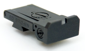
Wish me luck
Edit ADD:
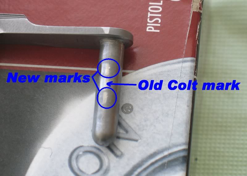
I forgot to show the FPS / barrel lug marks. Recall that I used an old used
FPS... I showed the new contact marks...
I would like to report vertical lockup measurements.
The Bar-Sto barrel 1-2 lug groove measured .045 deep out of the box. While fitting the rear hood length I wasn't able to get the barrel lugs to fully lift into the slide for what ever the reason. I decided to lower the 1-2 lug cut by .003 to see if this mod changed lockup or not. What ever happen next I don't fully understand but I rounded the lug sharp corners on the barrel and slide that allowed the barrel to achieve .046-ish vertical lockup. This equates to 46/48*100% = 96% vertical engagement. I haven't been able to determine if the 1-2 lug groove bottoms on the slide or not... I hope it does even though I measure 96% lockup.
I was able to keep end play to about .0005-.001 (no perceivable movement)
While waiting on for my Bo-Mar sights I ordered these from Colt:
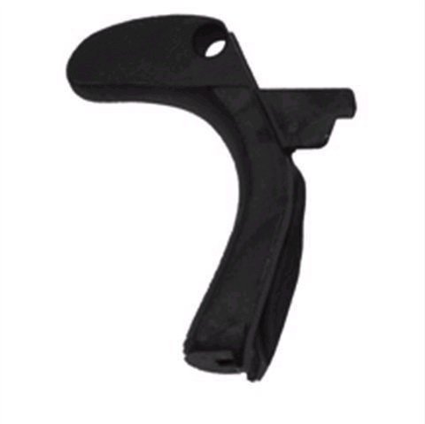
Traditional grip safety (I know... there is no such thing)
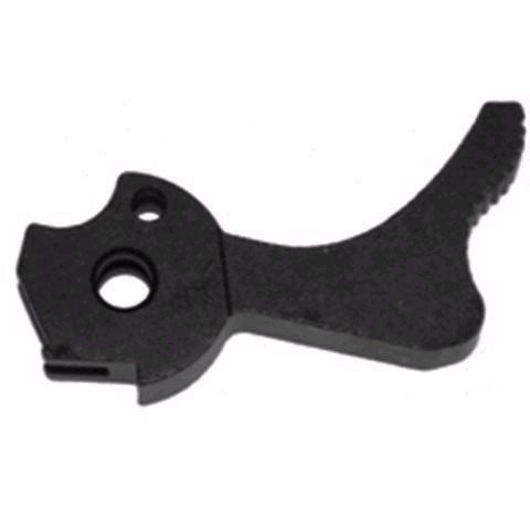
And Colt spur hammer:
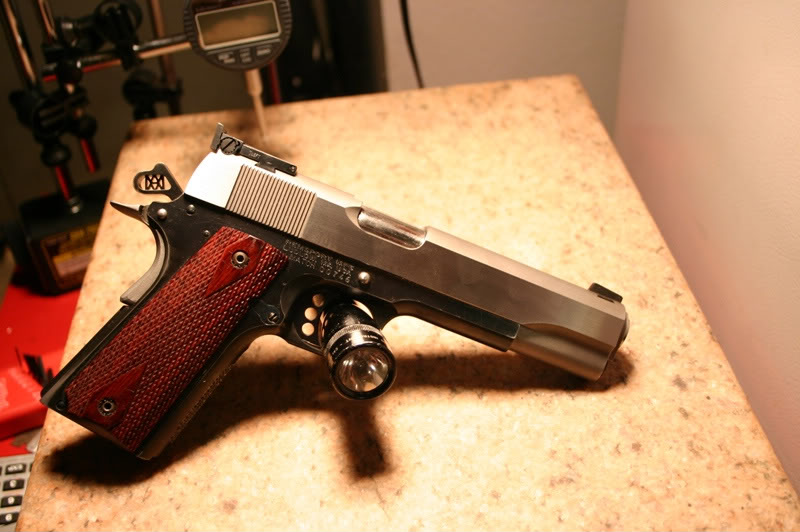
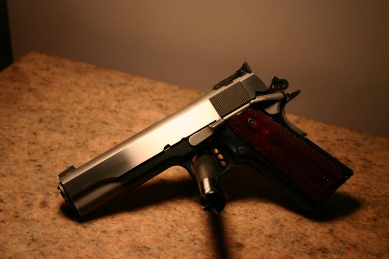
Now she has sights... they aren't the Ed Browns I tried to buy but Kensight/Novak are OK too.
Here is how she looks now:
Here is the Bo-Mar style Kensight rear adjustable sights:
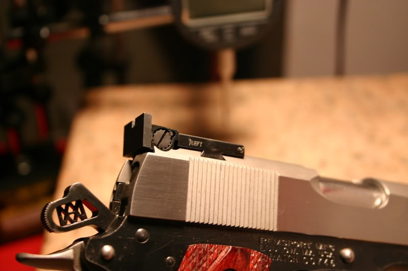
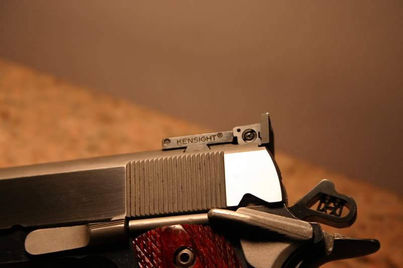
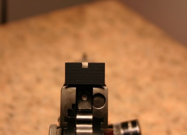
Here is the Novak front sight... I bought a .220 tall sight because I didn't know what height would work best with an adjustable rear sight... I installed my LASER bore-sighte then proceeded to file down the front sight until I was in about the middle of the rear sight's elevation adjustment and it just seamed reasonable... ironically it ended up .162 tall... go figure that I could have just bought a .160 tall front sight...
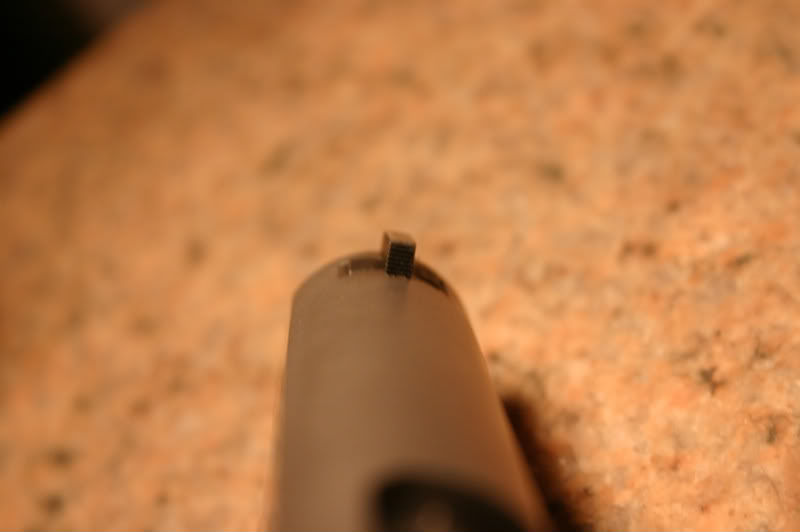
And the build continues...
I put 150 rounds of Federal American Eagle through here yesterday. I had one premature slide lock back. The range didn't have any way to shoot from support so I decided to try to hit a pattern of five 3" Shoot-N-See stickers off hand a 15-yards. My best run was consecutively hitting three sets of five before I fell off. I like this shooting because you have to reposition the pistol for the next target.
I started to cold blue the slide's working surfaces to help monitor bearing contact surfaces and got carried away... I cold blued the entire slide.
She will stay this way until I am confident enough with her to have her blued by Ford's Custom Gun Refinishing.
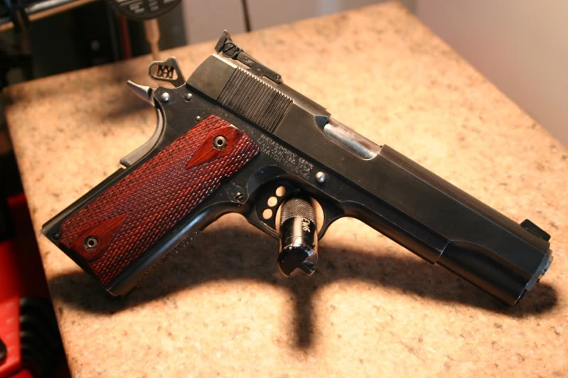
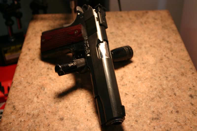
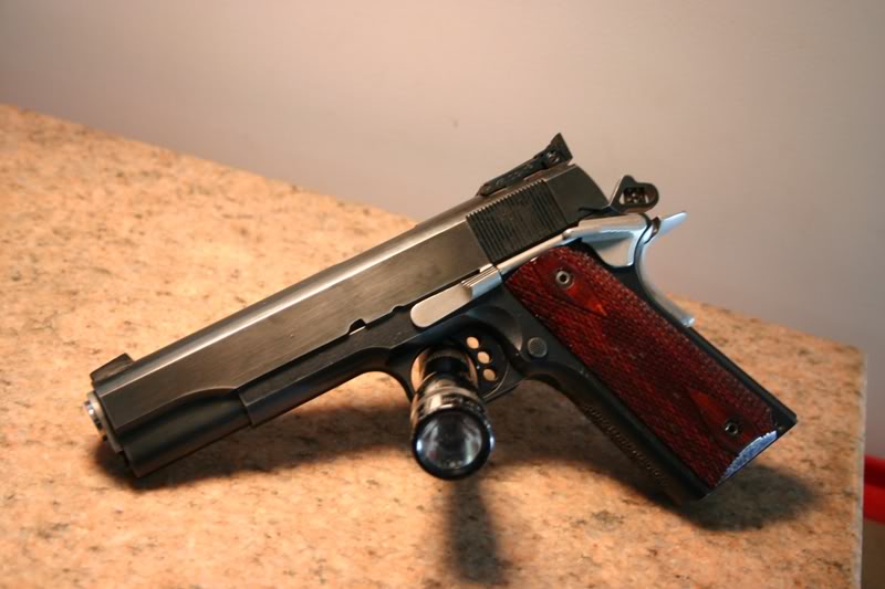
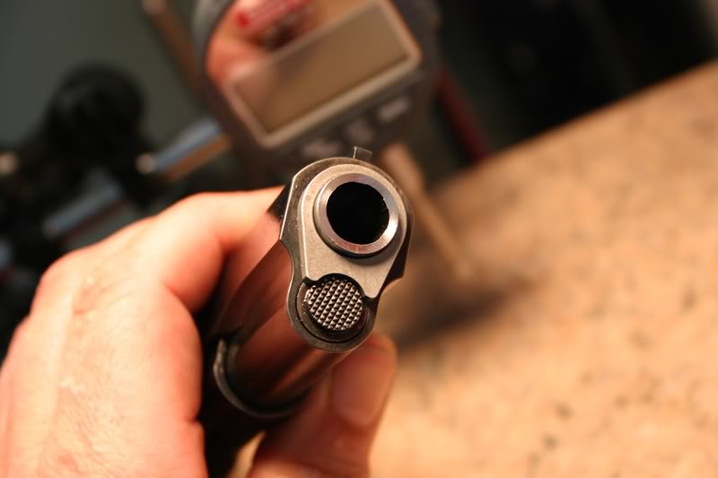
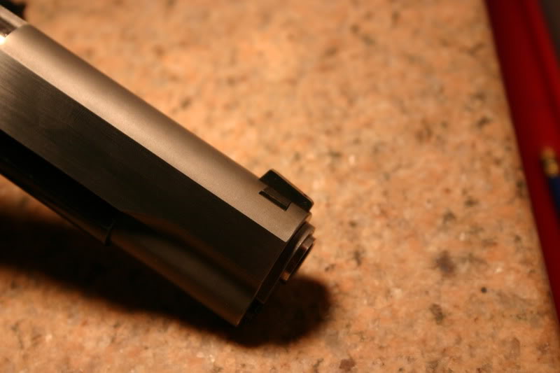
This weeks additions are:
Colt spur hammer.
Colt GI grip safety (although the frame has a .25 radius cut)
Solid long trigger w/ over travel screw (Old Pachmayr part I had)
Slotted Head grip screws
Other than changing the stainless Colt slide stop, grip safety and plunger tube for blue versions... functionally she is complete.
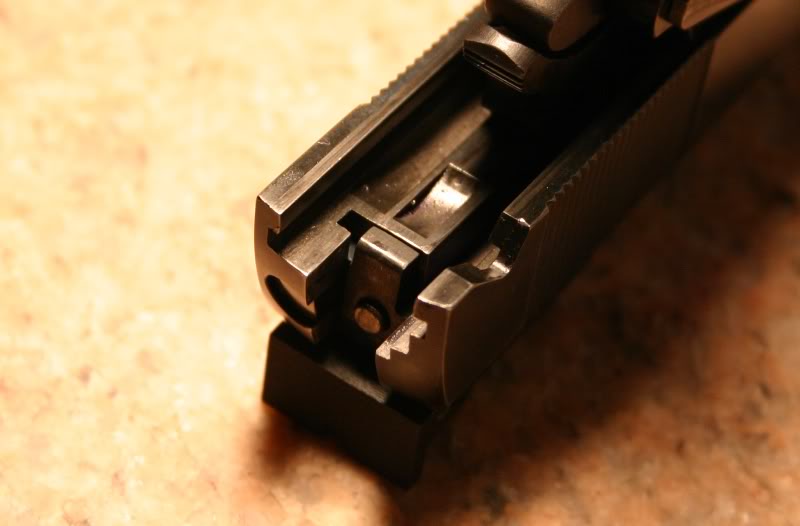
I just fit an EGW over-sized FPS... it's a series 80 that I had laying around but will work fine... I tapered the face to match the hammer angle.
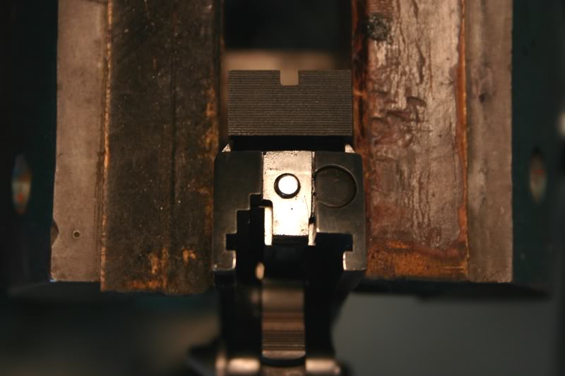
Here is a different perspective of how I like to fit these FPS puppies.
Quote:
So... How much in the dollar value has this cost you,Not counting the time
spent. Just wondering before I start a project like this. Kudos on the info
and pix! Very WELL done!
Hello and thank you for the kind words,
RemSport frame: $149.95 + Shipping $20.95 = $170.90 (free FFL because I won
the bowling pin competition at my range so my range traded the winnings for
the FFL)
Caspian Slide delivered $312
Bar-Sto Match Target Barrel/bushing: $199.99 + $7.01 shipping = $207.00
Bo-mar rear sight: $60
Novak front sight: $24
Colt MSH: $8
Ejector, grip bushings and other small parts: $30
All other part I had in my parts bin.
Total parts: $804
Tooling:
Power Custom 1911 Frame Support System $75
Lyman Trigger Pull Gage $55
Brownell lug cutter, slide pusher & barrel holder: $137
EWG HOOD LENGTH GAUGE $34
Brownell's barrel alignment block $40
Total: $341
Grand Total: $341 + $804 = $1145
Lessons learned = Priceless
Quote:
If you had it to do over... any of the tools not worth it for what they did
for you?... any others you wish you had gotten instead or in addition?
Hello, I only bought the minimum tools required for the job, used them all and was happy with their usefulness. I really like the Power Custom frame holding fixture because I have used it for many other small jobs.
I used my files and stones the most but didn't mention them in my list. I used my Brownell's hammer squaring file the most with my Kart Easyfit lug file next.

The next most important tools are my SPI drop indicator certified to .0001" accuracy:

And tool makers vise:

Quote:
Did you forget the rail gauge set or did you already have it?
I used a $30 gage block set and feeler gages to measure both the frame and slide rails:


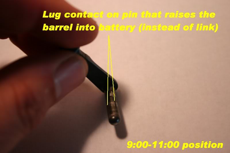
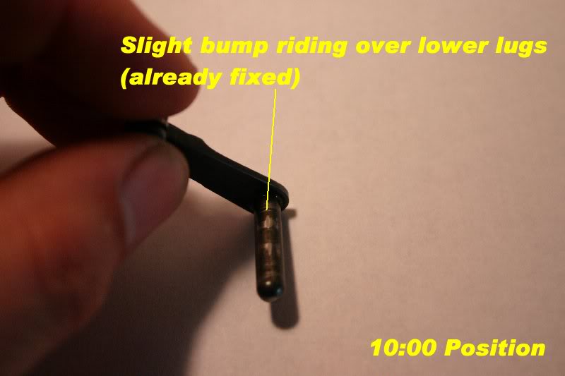
I would like to report on how my slide stop pin looks after this weekend. Recall that this pin measures .1986-.1987 which is right at the lower end of the pin size tolerance.
3:00-600
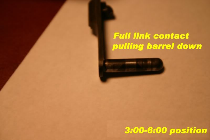
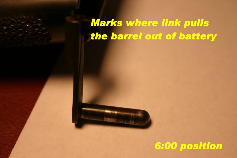
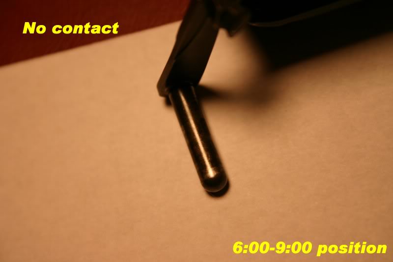
9:00-11:00
10:00
12:00 standing on barrel feet: (w/ flats worn on pin from .090-.100 flat on barrel feet)
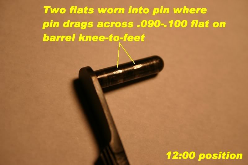
I don't know if this correct but it seams OK.
I don't know if the flats at 12:00 are normal but they explain why I can't use a .199 pin.
Quote:
I don't know if the flats a 12:00 are normal but they explain why I can't
use a .199 pin.
I don't think they are normal, at least compared to Petunia's. Petunia locks up tight with her link loose and there are no flats on her slidestop pin after about (as a guess) 15,000 rounds. A little crude scaling off your photo indicates the flats are about 0.040" wide (in the fore-aft direction) and some math shows that if they are flat, the pin's been worn down about 0.002" at those places.
This seems to indicate the flats got worn because the barrel was fitted too tightly and maybe because the barrel lug flats are too long. If you install the "upper" with no recoil spring and with the slide stop arm hanging down over the trigger guard, will the gun go into battery without using too much force?
Quote:
This seems to indicate the flats got worn because the barrel was fitted too
tightly and maybe because the barrel lug flats are too long. If you install
the "upper" with no recoil spring and with the slide stop arm hanging down
over the trigger guard, will the gun go into battery without using too much
force?
Yes, I reduced the "lockup" force a lot from the start of the build but I can still feel a slight drag across the .100 flat of the barrel knees.
Since I have never hard fit a barrel this way before I intensionally left the pin-to-lug clearance tight because I can always loosen it up later. I can spend more time lowering the the flat or tapering it a little to eliminate the full .100 drag but maintain the lockup.
Don't know if this good or bad... but I am enjoying learning about it... and slide stops are cheap...
EDIT ADD: I will drop the slide under its own weight now to see what happens...
I removed the return spring and pointed the pistol down with the the slide back.
The slide moves forward with little effort because there is slight drag as the disconnector drags across the rail. Once the disco enters the slide cut re-connecting the trigger she drop to battery under her own weight.
So the answer is "a slight drag".
But this is after the flats on the pin have formed.
Thinking about your last photo a bit more, I suppose there's nothing inherently wrong with the "final fit" being the flats worn on the SS pin - provided the corresponding lug flats are smooth enough to avoid further wear on the pin.
As long as the barrel returns to the same location within the slide after each shot - and continues to do so - what more could you ask for, eh?
Quote:
Thinking about your last photo... there's nothing inherently wrong with the
"final fit" being the flats worn on the SS pin... provided the corresponding
lug flats are smooth enough to avoid further wear on the pin.
Here is the corresponding surface that is purdy smooth... and if she wears more I can just start using a fatter pin.
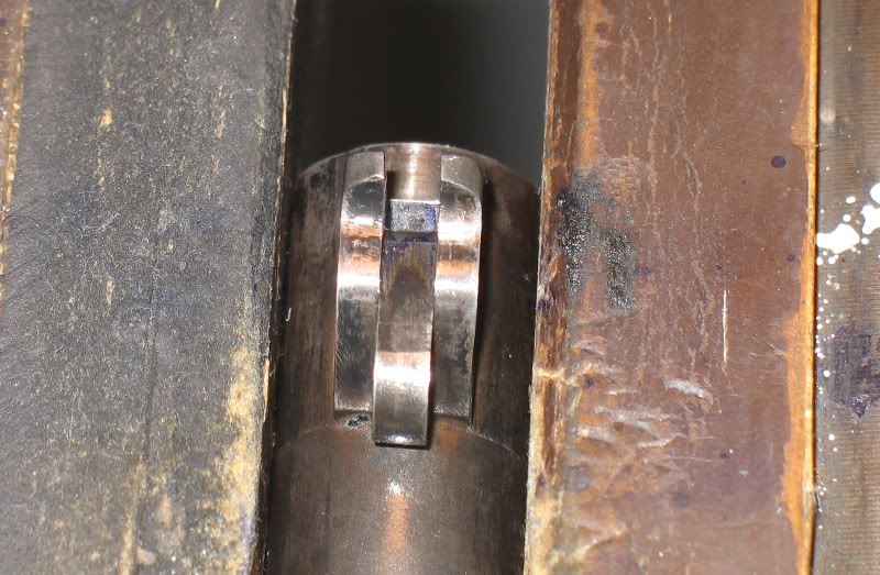
The lugs do indeed look nice and smooth. And with that large a bearing surface on the pin, my guess is the tight barrel lockup would last just about forever - or at least until slide & frame rail wear loosened it.
Now all you need is a Ransom Rest to see how she really shoots!
She is done... I don't plan on refinishing her anytime soon because I see no real need for that considering she is a target pistol.
I used Caswell stainless black to blacken the barrel:
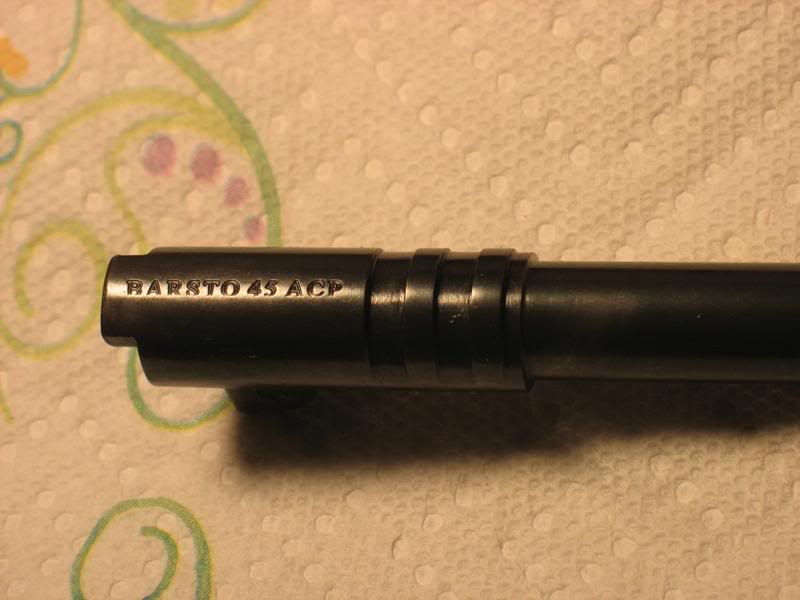
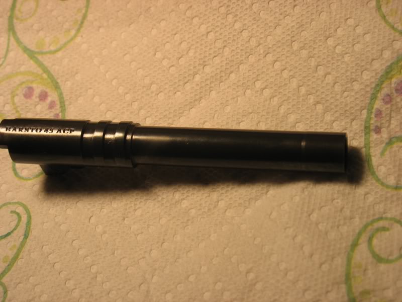
And here is the final product:
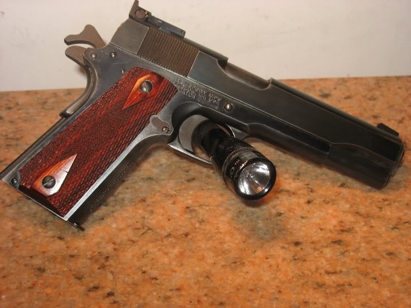
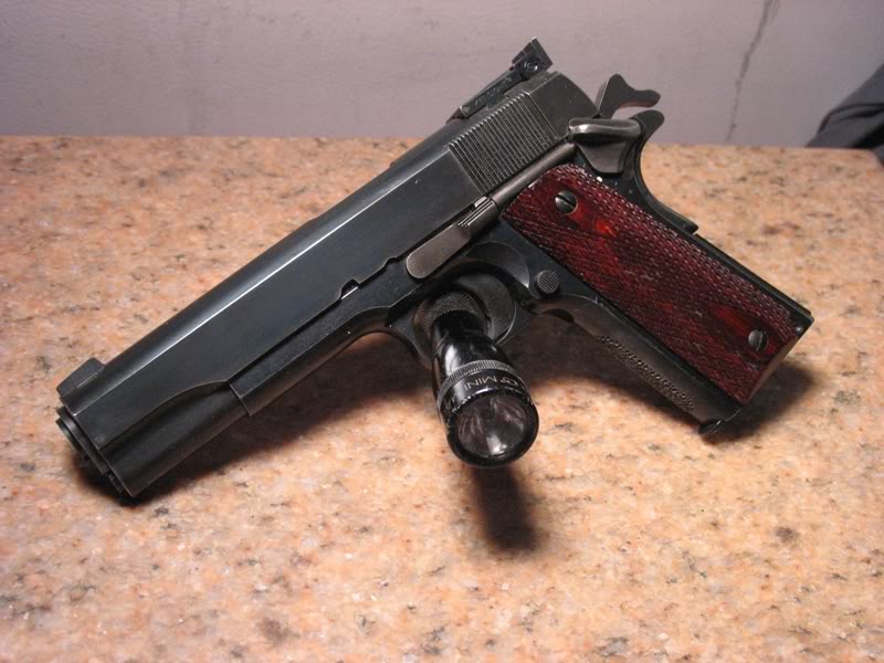
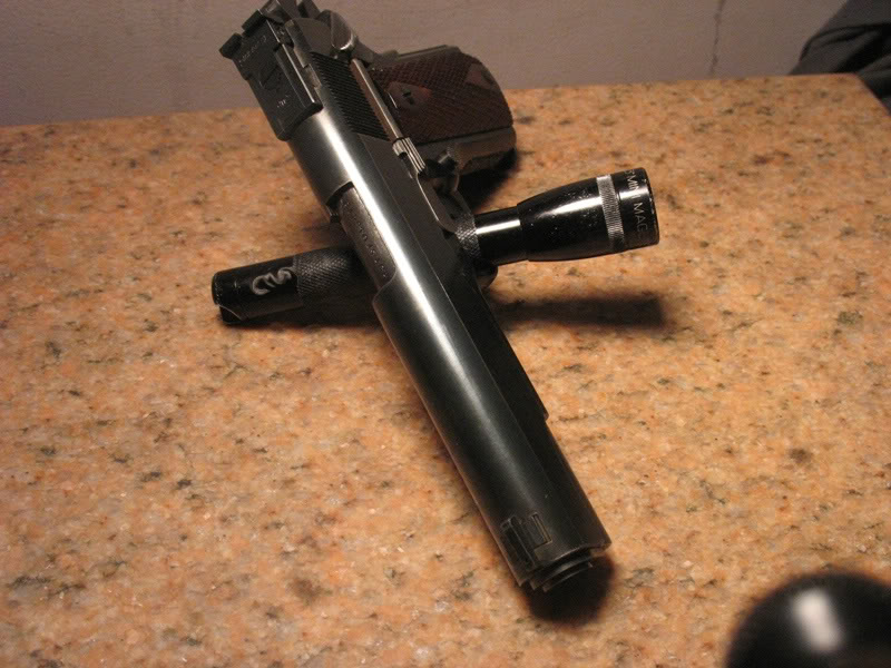
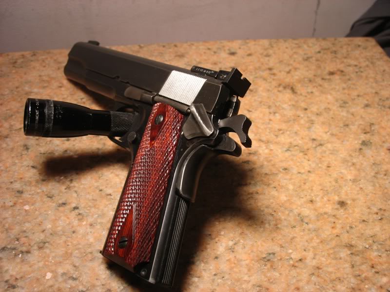
That consists of:
RemSport Match frame
Caspian Slide
Bar-Sto barrel and bushing
Novak front sight
Kensight Bo-Mar cut rear adjustable sight
Colt grip panels
Colt grip screws
Colt slide stop
Colt thumb safety
Colt plunger tube
Colt nylon MSH
Colt sear spring
Colt guide rod
Colt return spring
Colt spring plug
Colt grip safety
Colt spur hammer
Berryhill sear
Berryhill disconnector
EGW extractor
EGW HD higher Mag catch
EWG pin set
Springfield ejector
Pachmayr plastic trigger w/ over-travel screw
That's about all I can think of for now... I guess everyone can see I like Colt parts...
I decided that I don't like my 4.5# trigger much... the sear is a the bottom end of the an acceptable length and the disconnetor is a MetroArms MIM part.
I just ordered a Berryhill sear (current part but worked too much) and disconnector.
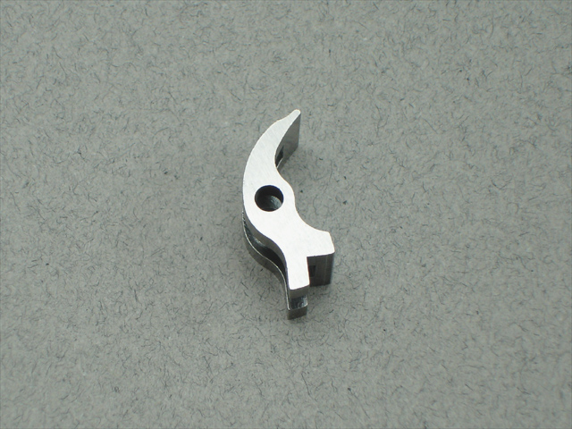
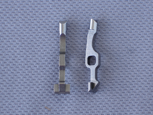
I plan to use these with my unadulterated Colt sear spring and shoot for a 3-3.5 pound trigger......
Is is supposed to be a target pistol....
BTW... I will use an Ed Brown sear jig... a magnifying glass... and tool makers binocular magnifiers together with the sear jig to make a 3-3.5 trigger... I will report my results.
What is the length of your sear? You're saying that's how you got it from Dave? Did he cut it for you?
I will measure the old sear later tonight... the current (old) sear was fit to another pistol manually then fit to this pistol using a Ed Brown jig. It barely had enough material to fit to this pistol so its can't be refit again.
I fit my other pistols manually using a tool makers vise and Dykem blue to stone the primary angle until I get near 100% hook contact during action without changing the primary angle.
As far as I know Dave gets his sears and disonnectors from from Extreme Engineering and doesn't to any more work to them.
I will use the same method I have successfully used before with the new parts:
1. Dykem blue the sear and hammer hooks
2. Assemble and dry fire.
3. Disassemble and inspect.
4. If there is uneven rub marks then I stone those areas until I get full hook/sear contact.
The sear jig is only used if I mess up the primary angle and need to recut.
My Colt hammer hooks measured .022 last time I checked....I will drop this down to .018-ish while I fit the sear.
Bare minimum, from memory (without pulling out my notes), .403" from the center of the hole to the tip of the nose.
Yep... it's short... I just measured .453 from a 109 pin which calculates out to be .453-(.109/2)=.399 (.3985) which is .0045 short...
Good thing I ordered a new sear.
I just looked at the sear length dimension in JK-Vol2 and the spec prints... they both state the sear should be .4045 - .003 or 0.4015 to .4045.
This makes my sear .4015 - .3985 = .003 under the low end... not .0045 as I mentioned before.
I got my Berryhill parts today.
The sear measured in at .402 with my calipers which is better than the old sear.
Here is how Dykem rubbed off after five dry fires:
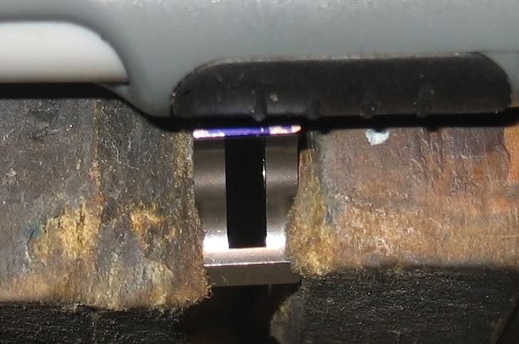
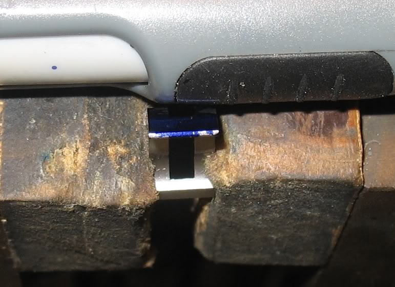
The sear is contacting both hooks and this contact is just fine for now... its hot in my garage now anyway.
I measured the Colt spur hammer hooks at a whopping .028". I will be lowering the hooks for my next step.
Quote:
I measured the Colt spur hammer hooks at a whopping .028".
Whopping? Not for a Gov't Model with a spec of 0.027 to 0.033 inch. Of course you knew that, but didn't want any newcomers to get the notion that 0.028" was an outlandishly large figure.
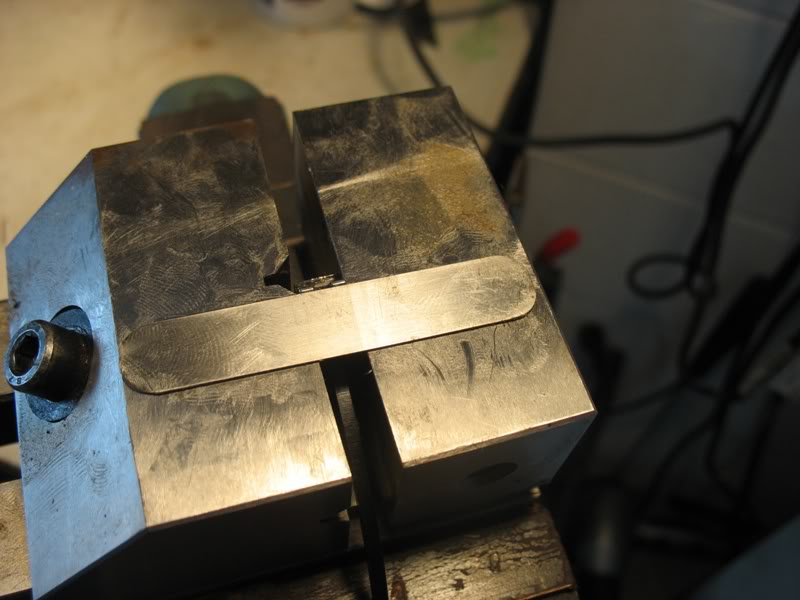
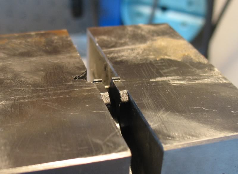
Lowered the hammer hooks to .020 for starters:
Clamped and leveled the hammer in my tool makers vise (thick with rust preventative)
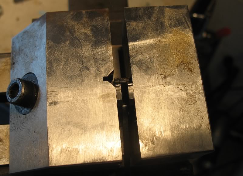
laid a .020 shim down and stared stoning the hooks down
Nice, neat, square .020 hammer hooks:
Next I will use my cut drill bits to place the hammer and sear outside of the frame to examine the sear to hook geometry... recall that the sear contacted both hooks... (this toolmaker's vise it the best $50 I've spent)
Here is the sear to hook engagement... the sear doesn't have sharp corners towards the side flats so the picture is a little misleading...
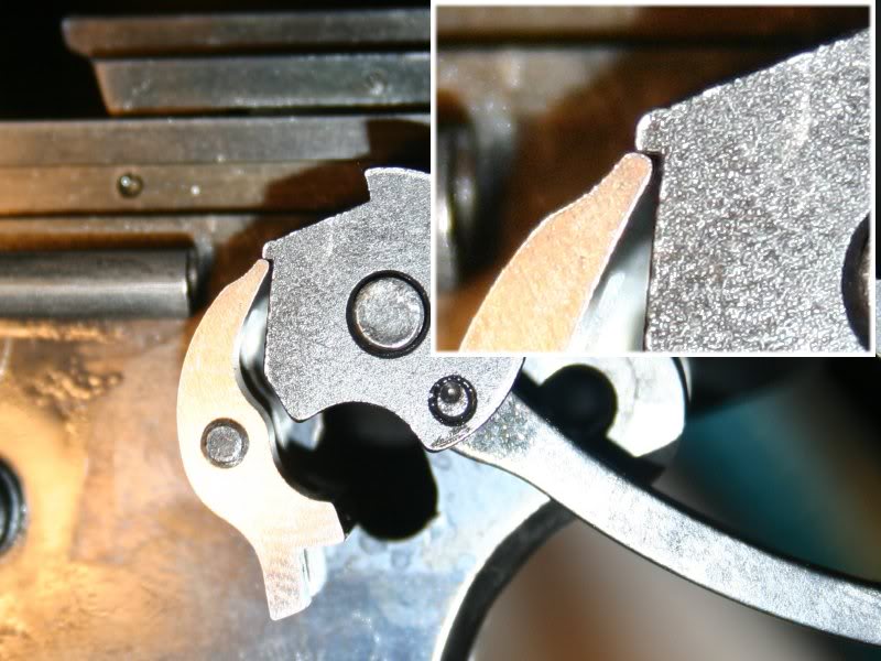
It looks OK to me... but I would like the more experienced members comment.
Crisp. Clean. Not one bit of creep... and she breaks clean at:
Now its time to work on the Colt sear spring.
Without a loupe... you really can't get a great idea of the engagement or squareness of the hooks. If you want a really handy tool for this... http://www.brownells.com/.aspx/pid=..._AUTO_SEAR_TOOL It magnifies the engagement and allows you to see everything in much better detail. You'll be amazed at the difference it makes. Of course, if you're only going to use it once, you're best off with a microscope of some sort.
From looking close at your picture, it doesn't look like your sear nose is quite going all the way into the pocket. To me, it looks like your hooks have a negative (I believe it's negative... maybe it's positive??) angle to it, which will cause your pull to take a bit more effort because as the sear tries to slip passed the hammer hooks, it has to essentially cock the hammer (or at least rotate it backward some).
I examine the sear with a jewelers magnifying headset and hand held magnifying glasses... I estimate together they about 20X total magnification...
I tried to hold the sear into the hammer for the photo but I can't be sure that the sear fully engaged the hammer when I took the photo... perhaps I can get some rubber bands and try the photo again...
The sear is very polished... so much so that the outer edges of the the sear are rounded off... I don't want to recut the primary angle to sharpen the edges because I have such good (I think) hook contact.
The hook cuts are original Colt cuts (aside from my .020 reduction) and expect that they are 90deg from the flat.
The sear primary and secondary cuts are original, untouched from Berryhill... I can Dykem and recut with my Brown sear jig... but I need to be foreced into this because I don't want to shorten the sear.
I will Dykem the sear and hammer hooks, dry fire, and take new pics.
.020" is a good number. If the angles are already cut on the sear by Dave (not just packaged, but actually cut), I'd leave them alone. I would be more inclined to think it's the hammer hooks aren't quite 90 degrees.
Nothing is ever perfect from the factory... and these areas are some of the biggest culprits.
There are some pictures somewhere, maybe on the other site of hammers and sears on a comparator... pretty eye-opening.
I really, really like the Brownells/Marvel Sear Jig:
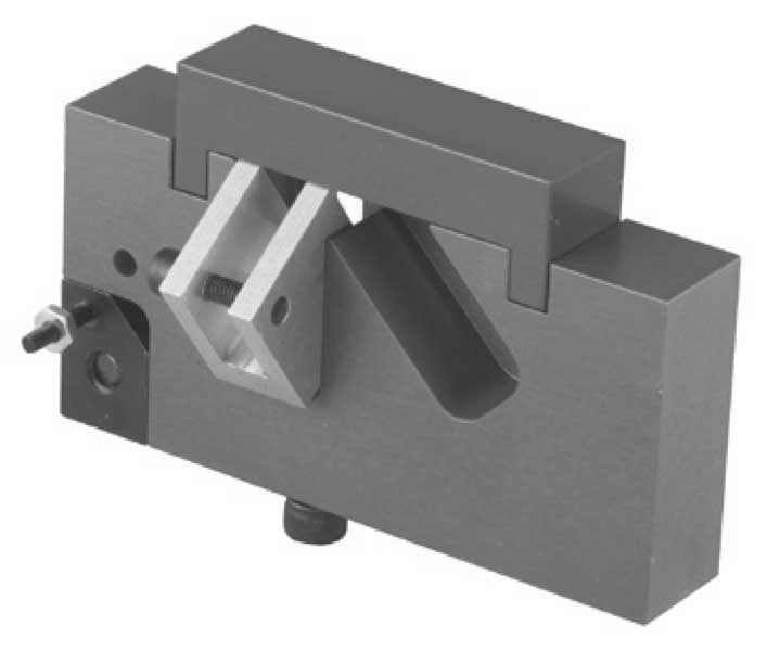
See this link for the instructions:
http://www.brownells.com/userdocs/learn/Inst-455 1911 jig.pdf
This jig allows you to set the sear angle to the specific hammer for stoning. Works a treat!
This is the worst sear/hammer jig offered by Brownell's and their Tech support agrees. They will refund without question. The tech I spoke with remarked he didn't know why it was still offered.
What's wrong with it?
The method of adjusting the sear on the fixture block is flawed.
The stud pulls out of the block.
If the stud doesn't pull out, tightening the nut down warps the sear, so it doesn't stay square.
After stoning the sear and trying it in the pistol, there isn't a way to re- register it in the same position. The sear is slightly shorter and will register in a different position when re-setting. Or if it is desired to polish the primary after the secondary the position is again lost.
An Alox stone rubbing on an Alox surface is poor engineering.
Grossly over priced compared to most others.
The Power Custom jig is repeatable as well as the simple Ed Brown, or Al Marvel (not related to Bob Marvel) and give repeatable results.
Oh, dear; I guess I'll have to undo all those really nice trigger jobs we did with it.
All I can say is... it worked for us; all four of us. When the book pistols are handled, the second or third thing said* is, "nice trigger."
I'll keep mine, thanks.
Certainly not denying that a great feeling trigger can be done without any kind of jig/fixture. Just relating the flaws of this particular fixture. Since the sear primary face is square to a line drawn from the sear pivot center, and extended to the tip, registering the sear on the fixture block with the hammer does not address this, nor allow a repeatable position. Simply stoning a sear primary angle, smooth, will improve the feel. But is it the angle it should be? The hammer hook face, and primary face of the sear are two different considerations, and are best addressed separately so control of the result can be had independently for each part.
A 3# -5# trigger can be great, and reliable, with several angle variables and flaws, but to have a 2# and less, crisp pull, be reliable and safe does require control of each component. This jig doesn't, and can't by design do this time and again. The Brownell's tech verified this to me some time ago. Buyer beware.
Even a Smith & Wesson Model 41 target pistol dosn't have a sub-2# trigger and its a 22-cal that dosn't kick like a 45.
Is it wise to shoot a sub-2# 45ACP?
What is the benifit over the 3-1/2# minimum trigger pull weight for a 1911 used in NRA Conventional (Bullseye) competition? (Those pistols are amazing).
I intend to settle for around 3-1/2# for this pistol... no need to go lower for me.
Quote:
Is it wise to shoot a sub-2# 45ACP?
Well, that certainly is a matter of choice. Steel plate/action plate such as the Steel Challenge has no such limit, just safe handling. Trigger pull weight is interesting as the trigger finger gets pretty educated. Learning to not assist the rest of the hand to aim or maneuver, just fire. Shooting fast, and accurately is a value in all forms of shooting.
The point is the Brownell's/Marvel Sear jig is a disaster.
I worked on the sear spring some.
I bent-up a safety wire loop to fit over the sear spring leaves - Colt sear spring are great because they have a cutout between each spring that allowed the loop to fit.
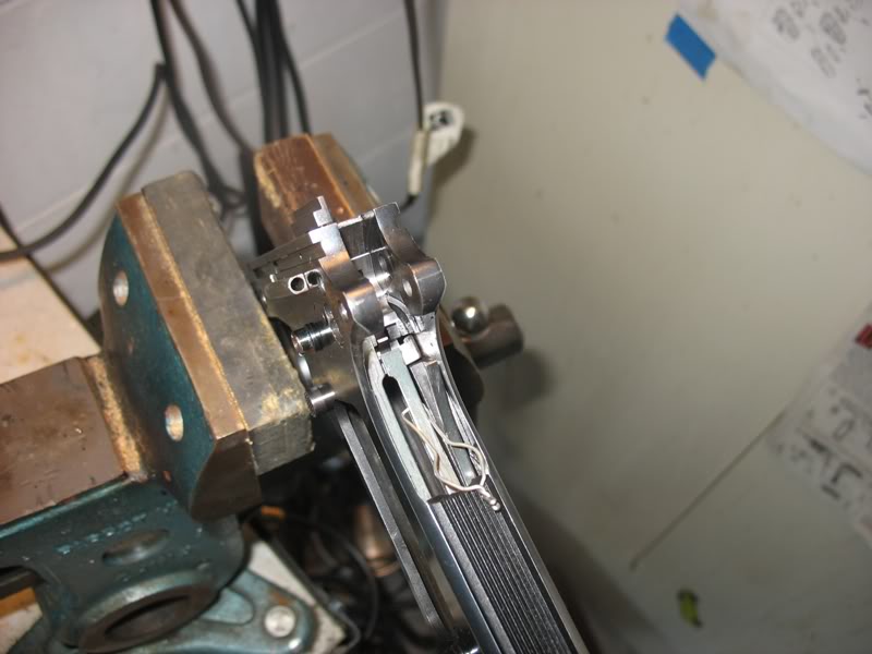
I measured the center (disco/trigger) and left (sear) springs around 2+ pounds each.
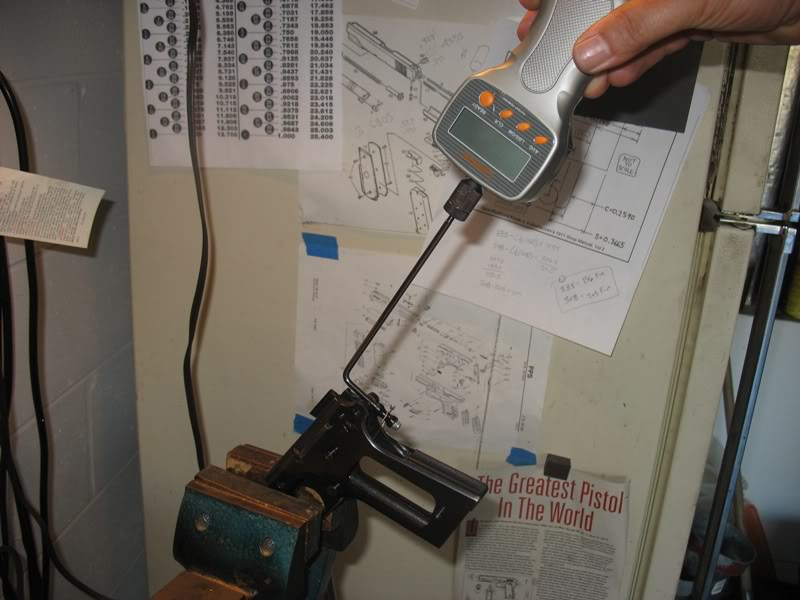
I slightly bent each spring while maintaining their relative shape and relationships.
Tested the trigger pull and repeated until I got around 3.25 pound trigger
Ten pull average is 3-lb 6-oz or 3-3/8 pounds.
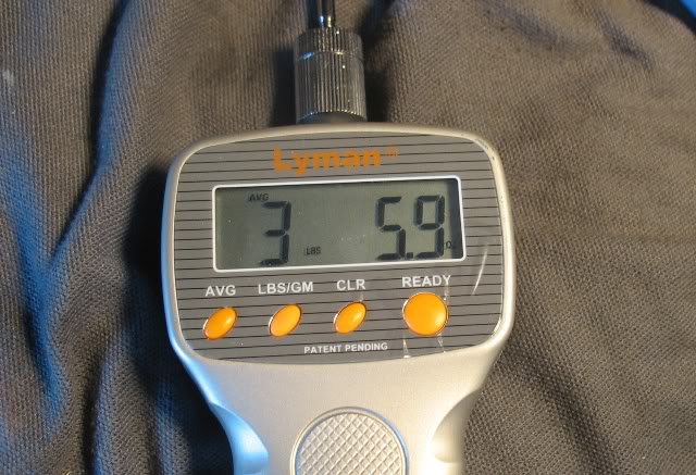
Now I have a very clean, crisp and light trigger... now I'll take her to the range for testing...
I dry fired this trigger about 50 times then decided to lower the weight just a little more... I bent the springs back one more time and now the trigger pull is between 3 to 3lb-2oz.
I dry fired the 3-pound trigger about 75 times and examined the sear face to see these even/consistent/full witness marks on the primary angle:
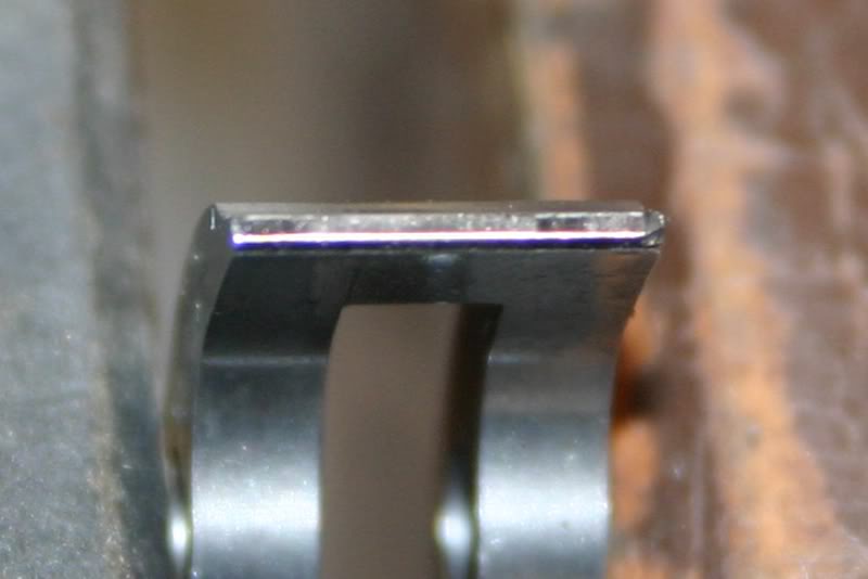
I'm done with the trigger... I will test fire the pistol Thursday night after bowling pins... wish me luck.
WHOA... what is that one the right side of the sear? It looks like a huge chunk is missing.
Yep, this is how it was delivered. I looks like a gouge. It could either be a wire EDM slag/miss, an impact ding from handling or an inclusion in the metal.
Originally I was going to send it back for exchange but after inspection I determined it is a cosmetic blemish that it doesn't affect form/fit/function because there are no raised surfaces so I kept it.
Personally, I wouldn't like to be even close to a 1911 with a 2 lbs trigger. Sorry, no matter who has done the work on it, I think it is an unsafe pistol.
The only pistol I've shot which had a 2 lbs trigger was my ex Walther GSP (or whatever the Walther .22 LR target pistol was named). And the trigger of that "space gun" was adjustable in a zillion ways. I had it adjusted at exactly 1.1 kg, the limit for the shooting she was doing required a 1 kg trigger minimum.
In what way would a 2# trigger be "unsafe", if it did not follow from a hard slide drop, and all safeties were in place, and working correctly. It can't go off without applying 2#s of pressure on the trigger face. This pressure is to only be applied when the pistol is meant to be fired and on a target, and not manipulate the pistol's movement towards or away from a target, and will not fire unless activated to do so. Ham handed gun handling is unsafe at any trigger weight. If you know your pistol, it will only fire when directed to do so. Being used to a 4# trigger, and then grabbing a pistol with a 2# trigger will feel light, and feel it goes off too easily, until you get used to it. When I'm handed a new pistol I always dry fire several times to get a sense as to the trigger pull. Learn to never manipulate, move or aim with the trigger finger, it's only responsibility is to pull the trigger when on target and intentionally fire. It is a choice, however and more difficult to tune than a heavier pull.
Oh, I've learned that a long time ago, my finger never goes inside the trigger guard, unless the pistol sees the target. But still, if you happen to sneeze towards the trigger, I have the creepy feeling that it will release the hammer. Not for me, sorry!
P.S.: Please do not take it personally, I just don't feel comfortable with very light triggers.
Quote:
In what way would a 2# trigger be "unsafe", if it did not follow from a
hard slide drop, and all safeties were in place, and working correctly. It
can't go off without applying 2#s of pressure on the trigger face.
These 45s aren't soft hitting 22s.
I feel a 2# trigger is unsafe because a 45 kicks pretty hard. Hard enough that some inexperienced shooters wouldn't be able to tell if the trigger reset and if the trigger did reset then any pressure on the trigger face could discharge another round. I think there would be unplanned discharges. Not something I would want to hand to someone and say "try this". Very few shooters really know how to properly use a trigger pull that light and I think it can get them into trouble.
Just my reason a 2# trigger doesn't belong on a 45...
What is most important with any trigger job is that you have a minimum of takeup, very little creep, so it breaks clean and no overtravel.
While I did address takeup and overtravel in my trigger I didn't discuss these items here.
Quote:
When this came up you may remember the context was about falling steel and
Steel Challenge shooting. Not Service Grade. I haven't any intention of
pointing any of my firearms at another person, and the intention of a Service
Grade 1911. Shooting people isn't my idea of fun. Shooting steel plate is. and
where a 2# trigger fits in.
But recall that this entire thread is about my target pistol build that I plan on having two sets of sear springs for two different trigger pulls.
One set will be used for target shooting like Bullseye competition with a 3- pound trigger.
The other set will be used for Hardball competition which requires a 4+ pound trigger.
I intentionally used a spur hammer, GI grip safety and use a blue finish for this build so I can compete in Hardball.

Either way my pistol will never have a sub-3-pound trigger.
I had much success at the range last week...
She's a shooter... for sure..
I decided to protect the trigger so I narrowed the 1/2-cock hook (really 1/4 on this hammer) and lessened the hammer over-cock.
I removed both sides of the 1/2 cock hooks: (this is all by hand and before I reblued the parts... so they may look ugly)
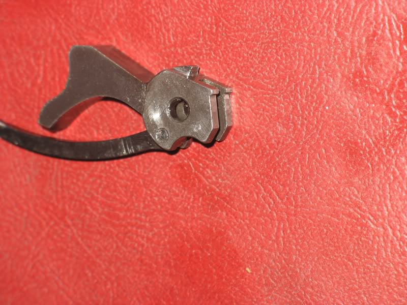
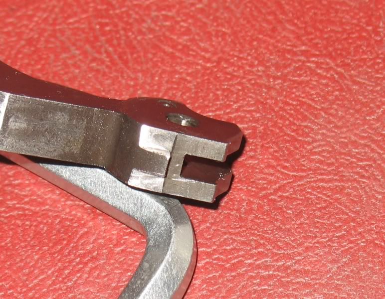
and lowered the hammer face to reduce the hammer travel when fully cocked.
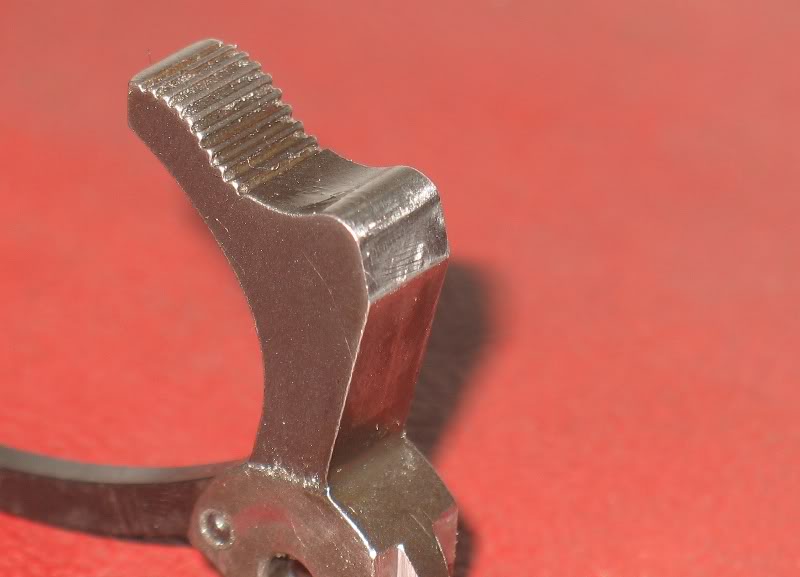
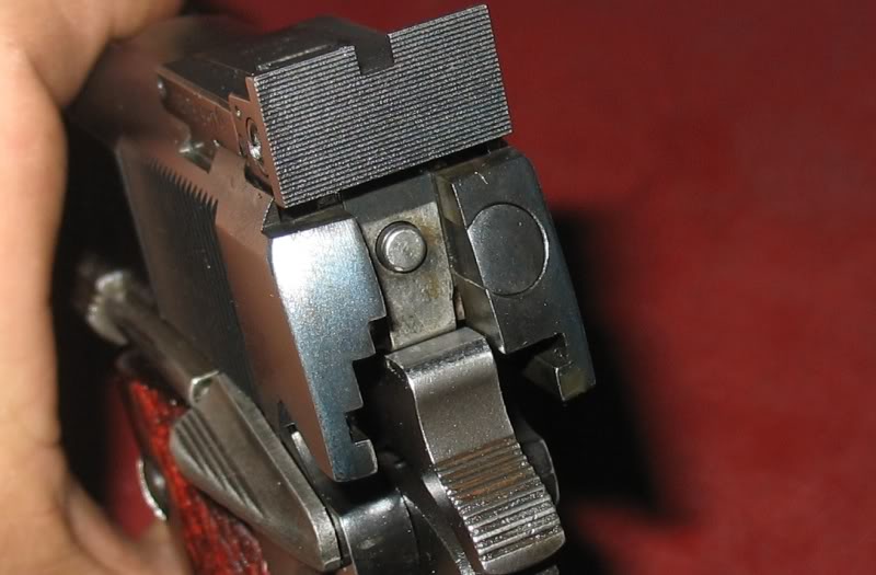
Next I will replace the stainless steel plunger tube, slide stop and thumb safety with carbon steel parts.
Very interested in your hammer mods... I'm assuming the idea for reducing the over-cocking is to reduce impact to the hammer/sear mating surfaces?... or are there other advantages?
I guess there shouldn't be enough repetitive use of the half-cock for the reduction in strength of the hook to be a concern?
Are these your ideas? I haven't been into 1911's very long, but I haven't come across these mods before... maybe I'm not reading the right books... since I haven't bought Walt's yet.
Fairly common actually in both production and custom.
Really... guess I just haven't had it pointed out and hadn't noticed. I thought it made too much sense for it not to have been done before, but I hadn't seen it.
Unfortunately I only own 2 1911's so far, and neither of them include these ideas.
Wouldn't the beveling of the top of the hammer also reduce resistance against the slide travel and slightly increase felt recoil?.. theoretically?
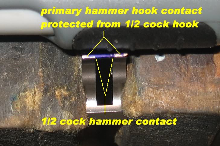
I removed the outer sides of the 1/2 cock safety ledge because it protects the sear surfaces and corners from being hammered by the 1/2 cock hook. Recall that the 1/2 cock hook is a different size than the primary hammer hook and therefor contacts the sear differently than the primary hammer hook. The sear both drags across the 1/2 cock hook during normal opperation and may fall to the 1/2 cock safey if the hammer slips. Here is a picture that shown the sear contact areas:
Reducing hammer overcock is supposed to reduce the impact of cycling on the sear face because it reduced the travel of the hammer until it contacts the sear face.
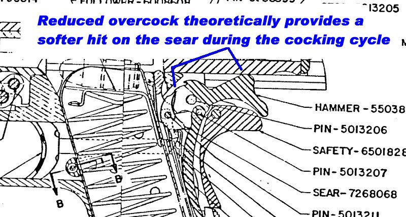
This is from a book with a "you-know-what" date of 1980...
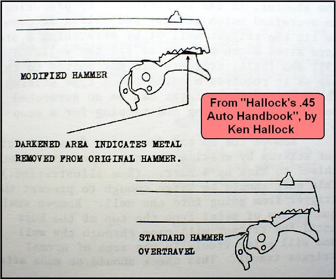
...but I'm not convinced there's any real need for concern over impact of the hooks on the sear nose during firing because the slide sort of eases the hooks down on the sear nose anyway. It's not like when you overcock it with your thumb and let the spur slip out from under your thumb.
It's probably one of those things folks look for in a custom gun because somebody else had it done to their gun and it sounds like a good idea - whether it makes any real difference or not. The stuff from which legends are born?
To be honest, I slipped with the file and left an unsightly mark on the hammer face.
Then I asked my self: What can I do to fix that oops?... the anwer was... lower the hammer face to reduce overcocking... it can't hurt and it looks cooler than an embarrassing file mark...
Perhaps I discovered how lowering the hammer face started... by accident... serendipity strikes again...
I thought the half cock mod sounded like the most valuable of the two... just wanted to see if there was something I was missing as far as advantages to the overcock reduction.
Quote:
Wouldn't the beveling of the top of the hammer also reduce resistance
against the slide travel and slightly increase felt recoil?
It might, provided the hammer face stayed in contact with the FPS/slide after the gun's fired. But it doesn't. Upon firing, the hammer is whipped back off the FPS as shown here:
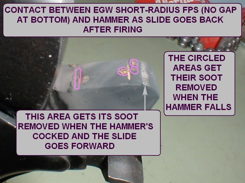
No soot removed means no contact between FPS/slide and hammer. Some say after losing contact, the hammer tang hits the grip safety tang and then reverses rotation to meet the disconnector rail which is now above it.
This is very true but the hammer quickly bounces off the disconnector rail and settles to guide along the disco-rail as the slide move forward. It is the hammer's movement from the disconnector rail to being trapped by the sear that we are trying to minimize.
This is a very crude illustration from Tripp Research's hi-speed video that shows the hammer travel I describe.

I know the picture is a little hokey but it illustrates my point.
So you are saying the small radius FPS is so aggressive at cocking the trigger that the FPS doesn't remain in contact with the hammer face as the slide travels back? I guess I'll have to black the hammer face on one of mine before firing to prove it to myself. It doesn't seem possible looking at it while cycling the slide slowly, but I realize it is a whole different ball game when you are actually firing the gun. Am I understanding you right that the hammer actually rebounds off the FPS to the cocked position and then the slide overcocks it by pushing back at the top corner of the hammer?
Many 1911's will show a contact point on the grip safety, left there by the
over-travel of the hammer as it is whipped back by the slides impulse.
daviscustom
2nd July 2011
I guess that is why the small radius FPS absorbs so much recoil... if it is
transferring enough energy to the hammer from the initial rearward impulse for
it to overcome the mainspring tension and actually cock the hammer without
direct pressure from the FPS... that's pretty impressive.
Quote:
So you are saying the small radius FPS is so aggressive at cocking the
trigger that the FPS doesn't remain in contact with the hammer face as the
slide travels back?
Yes. And there may be some evidence the same thing occurs with the current large radius FPS. This thread
http://forum.m1911.org/showthread.p...op+modification gets into this type of discussion at about Post #240.
But the overcocking Eric and I were discussing is that which occurs when the hammer's on the disconnector rail and the slide is starting to move forward. Regardless of the hammer shape, the slide will be accelerating forward at the same rate on its way back to battery. But when the hammer face geometry is changed like Eric did there's the idea that the slide eases the hooks down onto the sear nose more gently - thus lessening the impact. Maybe so. Maybe not...
...because after the upper part of the hammer is dubbed off to minimize overcocking, when the slide's going forward the hammer's still riding down to the cocked position using the same interface between the unaltered portion of the hammer face and the same FPS. If all that's the same and the slide velocity's the same, the impact's the same. Methinks.
Quote:
Many 1911's will show a contact point on the grip safety
All of my 1911s have this contact point... I think they have to... what else limits the hammer's reward travel? If you remove the grip safety and cycle a 1911 hammer the hammer will continue back and even over cam the sear.
Quote:
All of my 1911s have this contact point
Yes, of course, the point was the slide doesn't over-cock it that far by itself, it is the inertia imparted to the hammer that slams it back, and into the grip safety.
Quote:
It is the hammer's movement from the disconnector rail to being trapped by
the sear that we are trying to minimize.
While it kind of sounds like limiting the distance traveled would minimize the hook-sear nose impact, if the hook velocity at impact is the same the impact is the same. As a f'rinstance, if you smack your thumb with a hammer going 100fps, how far the hammer traveled before hitting your finger doesn't affect the amount of pain suffered.
All this ignores any (probably minor) reduction in impact just because whacking the hammer has reduced its mass.
Edit: All this also assumes the hammer remains in contact with the FPS as the slide goes forward to battery.
I Hate When This Happens...
...now I'm having second thoughts about what I said in Posts #216, 224 & 227. Fiddling with a 1911 and making some sketches almost have me convinced maybe impact can be reduced after all - but I can't explain why.
The frustrating part is it's easy to see how impact could be reduced to nearly zero if the amount of overcocking was nearly zero. But as I think that's a recipe for hammer follow, there's got to be some measurable overcocking just for reliability. And if there's some overcocking, then . . . [ooh, my head's starting to hurt!]
If its any consolation niemi, my TRP Operator has almost no over cock... its about the same as my home build... and the TRP has never missed a beat... ever.
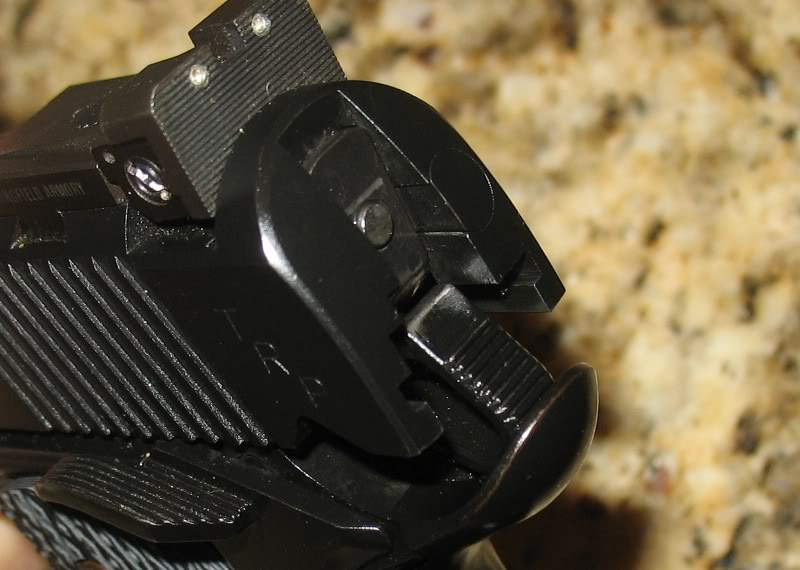
Neither have any of my other 1911s but it sounded good anyway.
What I can say is that the TRP's tigger has been the same for over 3,000 rounds.
The narrow half-cock notch has been done for a long time, and is a legitimate modification and has been incoorporated in some production ignition kits (we were just talking about EGW's the other day around here with this same modification).
If we assume the hammer is just released by the slide and falls freely, then the overcocking impact would be reduced because it would have less space to accelerate and therefore be swinging slower when it strikes the sear. Recall that the energy absorbed by the hammer is the same as the energy released from the spring, and less spring expansion means less energy released. Less energy=less speed=lighter impact.
However, if the slide is controlling the hammer's descent all the way down, then it doesn't matter how overcocked it is, because the speed it's going when it stops on the sear is completely controlled by the slide, regardless of how far it falls.
I suspect the latter is true, but I don't actually know it.
Quote:
However, if the slide is controlling the hammer's descent all the way down,
then it doesn't matter how overcocked it is, because the speed it's going when
it stops on the sear is completely controlled by the slide, regardless of how
far it falls.
This seems easier to swallow then the hammer being smacked so hard that it cocks from it's own inertia, especially given the power of the mainspring. I would have tested the theory today if I hadn't been at a wedding/reception all afternoon... so maybe tomorrow if someone doesn't beat me to it.
I am assuming that if I load a round in the chamber, insert an empty mag to hold the slide open after the shot, and then blacken the hammer face prior to firing... I will see if the FPS rubs the entire hammer face through the first half of the firing/reloading cycle. If I get marks on the whole face then the overcocking mod is of little value... if I get marks only at the bottom, top and impact points on the hammer face then I'll have to assume Niemi's first assertions are correct.
Any flaws in my test method? My plan is to hold the hammer overcocked as far as possible before dropping the slide (after firing) so I only get marks from the firing/ejection half of the cycle.
Quote:
I suspect the latter is true, but I don't actually know it.
I thought so too - up until a little while ago. I put a good coat of candle soot on a hammer face, manually overcocked the hammer while locking the slide back, released the hammer to make contact with the disconnector rail and then released the slide to let it go forward using the slide stop. Expecting to see a continuous but fairly short area where the soot got rubbed off, I was surprised to see three distinctly separate areas! The two areas in between where the soot remained seem to indicate the slide/FPS outraced the hammer.
Anyway, as seen in this photo...
...it appears the hammer did not stay in contact with the slide/FPS as the slide went forward to battery. The rubbed off area on the left corresponds to the area of initial contact when the hammer is manually cocked and then the slide is pulled back slowly.
It's beginning to look like my initial idea (much ado about nothing) was only a flash in the pan.
Its a kinetic energy thing...
If you assume the slide travels back into battery at constant velocity then there is no difference achieved by reducing over cocking. I its a kinetic energy thing, KE=/2MV^2, and if velocity is constant then the energy absorbed by the sear is not changed by reducing the over cock gap. Kinda like getting hit by a car traveling 50mph, it doesn't matter if that car just drove from across the state or from across the street before it hit you, damage is the same.
However if you assume the slide is accelerating on its way back to battery then the over cock distance represents a change in velocity (due to acceleration); therefore the kinetic energy is changing (increasing) as velocity is changing (increasing).
Question #1: So as the the hammer is handed to the sear is the slide traveling at constant velocity, or is it accelerating forward?
Question #2: Or is it perhaps decelerating at this instant as it strips and chambers a round. If so whats that do to your thoughts on reducing over cock?
Quote:
...it appears the hammer did not stay in contact with the slide/FPS as the
slide went forward to battery.
That was a little surprising, but if the slide does outrun the hammer then the hammer would indeed be accelerating forward (at whatever rate the mainspring allows) and reducing that over cock gap should reduce the energy at impact.
Are you sure the hammer did not stay in contact with the slide/fps? I can see the rub marks in your photo, and the gaps, but looks like contact may be moved from point to point across the hammer as the slide travels forward leaving what may only "appear" as contact voids? (I don't know if that is even understandable?)
Much to my surprise I just just burned up about 17 rounds of ammo... and lost two or three cases in the grass... and proved myself to be wrong.
I realized that since the hammer is locked back after each shot the only marks that could be made on the hammer face (except at the top) would be made as the FPS cocks the hammer so I just disregard the marking of the top edge and look for marks on the face.
I have one pistol with the small radius FPS, and one with a standard FPS (I tested both the same way, never cocking the hammer by manually cycling the slide). After firing a full mag plus a few extras through each, there was no visible marking of the hammer face between the mark at the base of the hammer face and the top. There was a faint smear (i used sharpie marker to black the face) on the one with the standard FPS, but after firing 8-9 rounds through each pistol there was nothing definite on either one until I started cycling the slide by hand, then the face was quickly marked... verifying that there was little to no contact with the bulk of the hammer face prior to hand cycling.
I can only surmise that in fact the hammer is smacked by the first rearward impulse and is propelled back to the cocked position (and then some)... and it is not being continuously pushed by the FPS.
If the hammer is flying back under it's own inertia, it seems that the bulk of the damage to the sear face and hammer hook would be from the hammer bouncing back to the cocked position... assuming the slide is not there in the nick of time to keep the hammer from rebounding back to the sear. If the slide is there in time then there is no problem... either way the overcocking mod does no obvious good that I can see.
I had high hopes that a scale drawing might help me figure out what's going on...
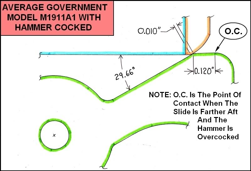
...but it didn't seem to help one little teensy bit! Maybe it'll help somebody else.
Is it possible the slide/fps impact bounces the hammer back into the grip safety, then mainspring pushes the hammer back into sear, all before the slide reached its most rearward position? I guess then a secondary contact with the slide disconnect rail.
Just some rainy day over-thinking.
Quote:
Are you sure the hammer did not stay in contact with the slide/fps?
Cripes, I'm not sure of anything anymore!
Niemi :On my ACII there is a slight step between the discon. rail and the bottom of the FPS... is yours the same or is it a perfectly flat transition? If the bottom of your FPS doesn't quite line up with the bottom of the disconnect rail, that would account for the skip in your rub marks.
Good call! The J-B Weld (step filler) is drying. Stay tuned.
Years ago, 1911Tuner has said it.
The action of the 1911 is vicious. The hammer gets kicked back by the slide, it hits the grip safety and bounces back. Don't expect the slide to gently push the hammer back, it ain't happening that way.
Thanx to Daviscutom's keen eye and J-B Quick Weld the step was filled, the "going to battery" test repeated and there was no sign of the hammer losing contact with the slide this time. As RobL thought, the slide/FPS seems to be in full control over the descent of the hammer hooks onto the sear nose.
Part Deux: Assuming the velocity of the slide/FPS remains the same it seems one way to reduce hook speed is to change the hammer profile over the 0.010" and 0.120" areas shown in the drawing into a straight line for a slower let- down and less impact. There's probably other & better ways too.
Eric: How did you alter the profile of your hammer?
I am assuming there is no way to change the answer (maybe a heavier mainspring), but does anyone have a good idea how we could prove the slide is there in time to keep the hammer from rebounding and hitting the sear? It would seem like trigger jobs wouldn't last very long if the slide isn't there to stop the rebound.
The more you remove from the top corner of the hammer it would seem more likely the slide may not catch the hammer before it hits the sear... possibly to the point of being counterproductive.
Quote:
I am assuming there is no way to change the answer (maybe a heavier
mainspring), but does anyone have a good idea how we could prove the slide is
there in time to keep the hammer from rebounding and hitting the sear? It
would seem like trigger jobs wouldn't last very long if the slide isn't there
to stop the rebound.
If the slide weren't there the hammer would not be cocked to begin with.
Did I miss something? I thought we just established that the only time the hammer is under direct control of the slide is when it is let up as the slide comes forward into battery. I'm guessing the slide is probably there to catch it, but if the hammer is traveling back with it's own inertia (slightly ahead of the slide) then it's conceivable the hammer could rebound before the slide catches up.
So your thinking is the slide has flung the hammer back and it may come back in time to crash the sear just to be flung back again? Evidence that the hammer does lose contact with the slide is evident by the mark associated with it being cocked further than the slide can, and in some heavily shot slides a ding that occurs around the disconnector cut as it bounces against the rail on it's presumed return to contact. That is interesting enough for me to say wow. The value for the eased hammer to limit over cock is to ease the hammer back on the sear as the slide goes to battery. What's the harm?
I'm guessing the slide is there to catch it I just wondered if removing the part of the hammer face that is responsible for overcocking could allow the hammer to travel up to catch the sear before the slide got there?
Quote:
I'm guessing the slide is there to catch it I just wondered if removing the
part of the hammer face that is responsible for overcocking could allow the
hammer to travel up to catch the sear before the slide got there?
Doing so would mean that the hammer would go to half cock during hand cycling, and when loading from a mag with the slide closed. I think this would push the envelope of trouble free operation.
I don't think I stated my thought very clearly.
If you assume that the slide makes it back in time to keep the hammer from rebounding off the grip safety and hitting the sear (I'm guessing it probably does), the extra meat on the top corner (that Eric removed from his hammer) gives you an extra margin to make sure the slide catches the hammer before it hits the sear. As you remove the extra material to reduce overcocking, that allows the hammer to rebound further and rotate back closer to the sear before the slide catches it... so if it was a close race between the hammer hitting the sear and the slide catching it first, it seems to me there is the potential to remove the top corner of the hammer to reduce overcock and inadvertently remove enough that the hammer could rebound back and hit the sear before the slide gets there... doing more harm then good with the hammer mod.
My question was: does anyone know how you could tell where the slide is when the hammer rebounds? I'm guessing it is there where it needs to be to prevent the hammer from smacking the sear on the rebound... just trying to figure out if there is a good way to know... probably just over thinking things It's contagious this weekend.
Quote:
but does anyone have a good idea how we could prove the slide is there in
time to keep the hammer from rebounding and hitting the sear? It would seem
like trigger jobs wouldn't last very long if the slide isn't there to stop the
rebound.
I just checked out a couple of the Tripp high speed videos and from what I could tell the slide contacts and pushes the hammer all the way back. It certainly looks more like a long steady push than a hit and bounce.
Once the hammer gets back there there is a lot of bouncing off the grip safety and under slide/disconnect rail.
Quote:
If you assume that the slide makes it back in time to keep the hammer from
rebounding off the grip safety and hitting the sear (I'm guessing it probably
does)
There's no reason to assume - your gun will tell you. As someone previously mentioned, just look at the disconnector rail for the mark made by the hammer when it rebounds. On my 5" wadcutter gun that mark is 15/16" forward of the FPS-slide junction and indicates it was made when the slide was a bit less than 1/4" from its fully recoiled position.
Quote:
Eric: How did you alter the profile of your hammer?
I used my tool maker vise and eyeballed the original Colt hammer face.
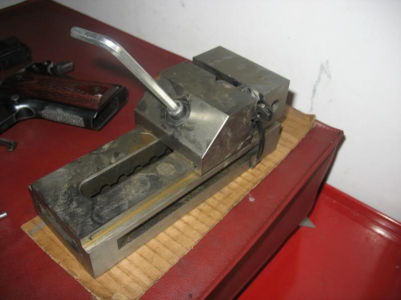
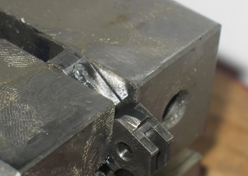
I used the vise to remove the 1/2 cock hook too. I used a height gauge block with a gauge pin to protect the inner part of the 1/2 cock hook like this:
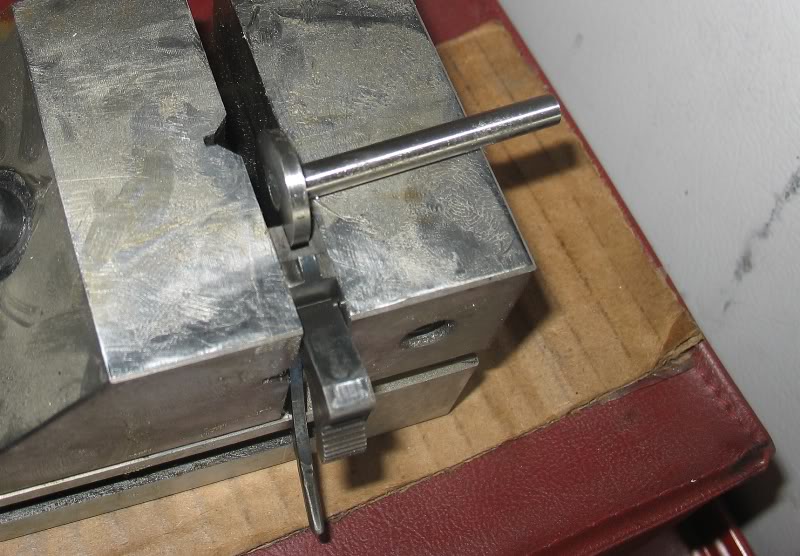
Here are the results. I like to cold blue my work then cycle the pistol to see where the blue wears off.
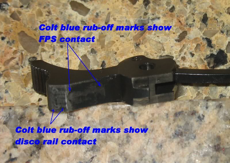
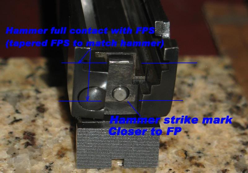
Lowering the hammer face also lowered the hammer contact mark on the firing pin stop. This lower contact must help to reduce the mechanical leverage of the system and should help the small radius FPS reduce muzzle flip.
If we could only quantify the effects of the modified FPS?
Coming soon... to a thread near you...
I orderd two single axis accelerometers.
and a small data acquisition system:

I plan to use them to measure recoil and muzzle flip. Then I will change the system to learn if it changes measured recoil.
I will also attempt to measure shock buffs too...
Wish me luck... I hope this system if fast enough... it can measure down to 4ms...
Niemi: My pistols aren't talking... the ACII only has marks that appear to line up with where the cartridge hits coming up from the mag well. Maybe I don't have enough rounds through her yet. My stainless Springfield has what appears to be a mark from the hammer, but it is a continuous smear from the FPS forward about 1 1/8"... no real impact points that I can see on the disconnector rail. This slide has three letters stamped, and a three digit number hand engraved in the disconnector rail so that makes it harder to decipher the wear marks.
Eric, I look forward to hearing more about your recoil tests... very high tech... hope it works.
Sorry my questions about your hammer mods took things off on a tangent... I should have taken my ball and went to play somewhere else.
QUOTE

This is a good picture to consider the stop. Notice how the stop is narrower than the rail? Why? Because the stop used, is by design, to fit the Series 80 style pistols, and also to work with the offset ejector used in 9mm/38sup, Commanders and Officers. And some full size such as Para. It does not fit well however in a Series 70 style, as can be seen by the fact it doesn't cover the rail itself. It's over cut. Recommend using the EGW 70 Series stop and fitting it to the individual pistol even a Series 80 style with the offset ejector for a complete fit match. Not sure why it's short also, but may have been over cut when fitted, this leaves the rail corner exposed to the hammer jogging over it.
Good eye... I talked about this FPS many posts ago... I used a Series 80 firing pin stop because I had one left over in my parts bin... no other reason than that... it was convenient... I posted the picture to illustrate how my hammer mods changed/lowered the hammer contact mark on the FPS... I will eventually replace it... no need for now...
The series 80 FPS should have no influence on function, wear or durability. None of my Colts have a problem with this FPS and I don't expect any problems with this pistol.
Here is a different perspective:
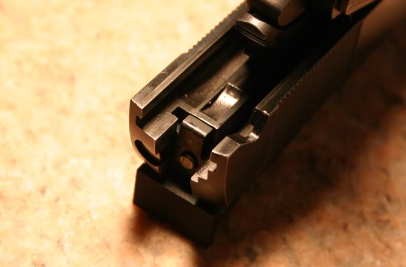
This one is a little short, meaning that the bottom isn't completely flush with the disconnector rail but just a bit below it. This isn't optimal but so far is hasn't caused any problems. It is this way only because this FPS was fit to another pistol and I decided that it is better to have the FPS below the rail than above it. The disconnector rail rear corner is in great shape...
Perhaps I should order a EGW slide stop soon...
I have the the regular FPS that fits a little better I can use.
I plan to use both FPSs in an shock/impact test I will run after I get my accelerometers.
Here is a good picture of one of my other 45s that shows how much/little the FPS bottom surface is actually used:
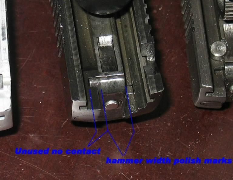
This is an original Springfield TRP production 45....completely original..
The unused area to the left is removed on Colt series 80 pistols to make room for the lever that pushes on the firing pin block plunger. A series 80 Colt is shown to the right in the picture above.
Edit Added:
For reference I added this picture of another one of my 1911s. This is a home built with a series 80 FPS (Colt) installed on a series 70 slide. This pistol has fired over 3,500 rounds and shows no signs of a problem using a series 70 FPS...
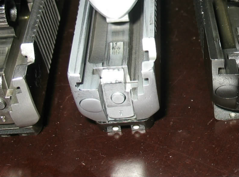
The potential for a problem in using these stops cut for a Series 80 with offset ejector is they are more susceptible to cracking from the ejector clearance cut corner to the firing pin hole. Some hold up well and have received some from the supplier with a crack. This one appears to have a crack.
http://i536.photobucket.com/albums/...ewgewg/003b.jpg">
Quote:
This one appears to have a crack
Fortunately I inspect parts for cracks and other evidence of fatigue every day at work. Rest assured that this slide is not cracked.
If you receive cracked slides from your suppliers perhaps they are not properly stress relieving the metal during manufacture.
Quote:
If you receive cracked slides from your suppliers perhaps they are not
properly stress relieving the metal during manufacture.
Not discussing slides. Series 80 firing pin stops with the offset ejector cut, note the firing pin stop in the picture, appears to be cracked in the corner to the firing pin hole.
http://i536.photobucket.com/albums/ff327/ewgewgewg/003b.jpg">
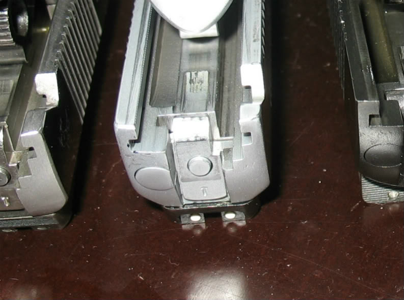
Quote:
Not discussing slides. Series 80 firing pin stops with the offset ejector cut,
note the firing pin stop in the picture, appears to be cracked in the corner
to the firing pin hole.
Thanks again... I will go look that the FPS... What does if matter if the FPS has a crack from FP hole to the corner?
Quote:
What does if matter if the FPS has a crack from FP hole to the corner?
Well... I'll let you be the judge of that. It's a reject part in my book.
You spotted it... great job... yes there is a crack...
I tried to ink it to help bring it out...
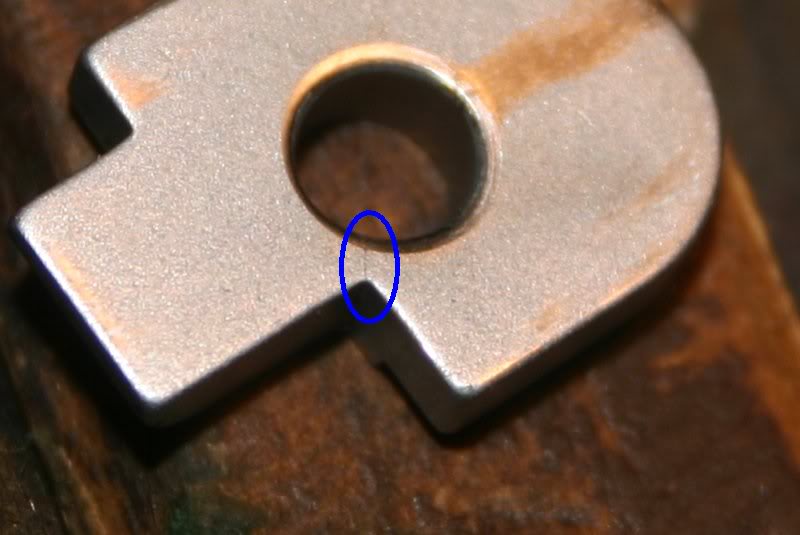
Thanks... I still don't see what this crack hurts... the FPS locates the firing pin, holds the extractor and in an impact surface for the hammer... and this one has thousands of rounds and more dry fires on it...
Yes, the Colt has a much thinner X-section next to the firing pin hole.
Perhaps I should fit a EGW, Brown or Wilson and send it off to be chromed... plus it will match the slide cut better...
The close one is for a 9mm/38sup with the offset ejector. The Ed Brown Series 80 is for a 45 acp. When firing pin stops break they start on one side, and then the other. Parts can go flying at that point. According to Wilson Combat's website the firing pin stop is the most common part broken.
Quote:
The close one is for a 9mm/38sup with the offset ejector. The Ed Brown
Series 80 is for a 45 acp. When firing pin stops break they start on one side,
and then the other. Parts can go flying at that point. According to Wilson
Combat's website the firing pin stop is the most common part broken.
Thank you very much CAW, this is very helpful and informative.
I just noticed that Colt only sells the offset ejector style FPS. I don't know how long they have been substituting these parts but my 2007 Colt LTWT Commander has the 9mm/38sup with the offset ejector style FPS and even the slide is cut to match... but its a 45ACP...
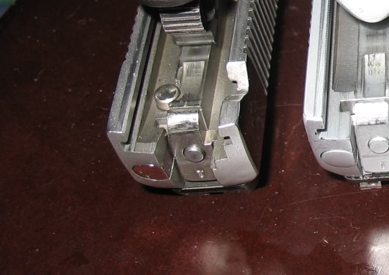
It must all be for the sake of cost savings... I can hear the board meeting conversations now "you know what we can do to..."
Quote:
I just noticed that Colt only sells the offset ejector style FPS.
Hmm, that's because Commanders use the offset ejector. Colt's use of the Series 80 9mm/38 sup firing pin stop is a "one size fits all" approach, but is correct for your Commander.
Quote:
I just noticed that Colt only sells the offset ejector style FPS.
It's because it's a S80...
I am going to order new FPS now.
Fortunatly Wilson makes square bottom FPS now.
I'll order stainless for the chrome 45.

And carbon steel for my current build:
Quote:
It's because it's a S80...
I can only find Colt S80 FPS for sale anywhere...
Colt FPS for sale at different suppliers:
Midway
http://www.midwayusa.com/browse/Bro...**&brandId=2084
Brownell's... no picture.
and even Colt only show one style (series 80) FPS on their web sights.
Eric, let us know what you actually get from Wilson. When I ordered one of each, I got two somewhat different designs. One had no radius, the other, a small radius.
Go figure.
EGW has both in Series 70, my choice to fit to any configuration.
Both of my Wilson SB-FPS have a sharp lower corners.
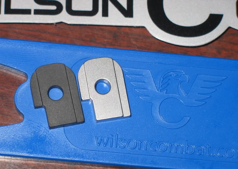
They are not oversized on the width like EGW part is but my stainless was about .010 long on the bottom when I fit it to my chrome 45....
No more crack... and much more material between the FP hole and notch corner... thanks CAW
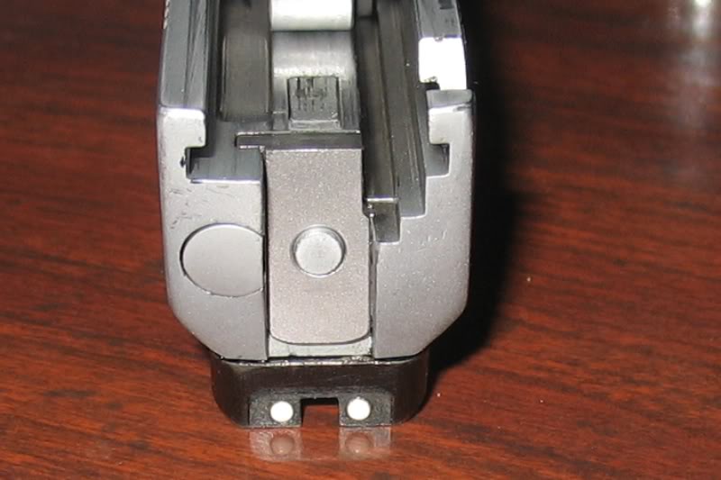
Excellent!
Dunno what George Smith (EGW) thinks about Wilson's entry into the square- bottom FPS market! George first introduced the square oversized FPS twenty or more years ago (I have an ad someplace from the '90's); 1911Tuner here on M1911.ORG schooled us in its benefits. Thanks, Johnny!
I just ordered the last parts for this build...
Recall that I installed stainless parts that I had laying around because they were convenient... here are the carbon steel replacement parts that I ordered from Colt...
I ordered:
Colt Plunger tube
Colt Slide Stop
Colt WW-I thumb safety ( the only supplier I know that sells this style TS)
Colt serrated Mainspring Housing
Here is my home build pistol with my new carbon steel plunger tube, slide stop, thumb safety and serrated MSH (out of the picture angle) installed...
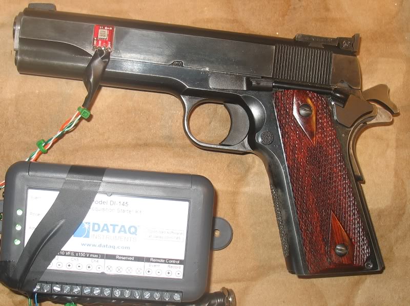
This picture also shows an accelerometer attached to the slide... I did a serise of test last weekend that were a big success... I got a lot of data... I will now make a fixture to firmly hold the pistol and re-run the accelerometer tests that may prove or dis-prove everything from shock buffs to square bottom FPS...
Make sure the velocities are well within the parameters of the chip. They were doing some db tests on muzzle comps in the Keltec forums awhile back and it was apparent the sound spikes were outside the range of the sensor which caused some arguments about the validity of the comparisons being made etc...
Beyond that... THIS IS AWESOME! I love it when the electronic sensors get broken out.
Maybe build a boot on the leads with some rtv silicone? Seems like those might break off from repeated bending in a few cycles. The silicone won't bond to the steel, but if you had an adhesive interface that it will bond to, it would be a stronger support.
Please don't worry... this isn't my first rodeo.
all of these items are considered....
Here is a glimmer at some data...
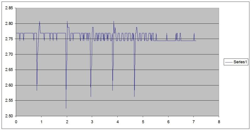
Tease.
Now I wanna know the specifics. That's 5 rounds, rapid fire, yeah? Hammer strike on the top? No, because it's post-primary impulse... Counter recoil/correction? No, back to battery slap, lugs to stop. This is so much fun.
I guess a weaker range on the sensor might tell more about the more subtle movements if it didn't damage it?
Sample rate? Resolution?
Throw another axis on there and we could learn about the effects/dynamics of comps and front end weight, etc.
Sorry if my enthusiasm is in any way grating. This is gonna be good stuff.
This data was from my "proof of concept" tryout to determine if I would get usable information from a 45 instrumented with an accelerometer. I did so I will choose better stuff for the real tests.
This data was taken with a 250g accelerometer which outputs a high linearity (0.2% of full scale) -5 to +5VCD signal that was read with a daq with a sample rate of 240Hz (4ms) and 10bit resolution.
These instruments where chosen because they are cheap... $30 accelerometer and $30 data acquisition box with software.
The graph/plot above was generated with Excel and the independent axis is time. Which means that this shooter started his first shot at about one second and ended his fifth shot at about 4.75 seconds.
I calculated that each shot (Federal 230gr range ammo) generated roughly a 40g 15g hit between the slide and frame. Again, this equates to a roughly 40 15 pound momentary hit because a slide weighs roughly one pound....
The small blurbs are essentially noise generated by the shooter moving the pistol around and are exaggerated because I had to scale the output from the DAQ up to see the data...
I will choose better instruments for my next test but this one was a success.
I want to remind everyone that:
+I am not a gunsmith
+I am not a 1911 expert
+I am not a 1911 teacher
+I am not a machinist
+I don't intend to present my material as an instruction of what to do
+This thread is only a diary of my first complete, fit everything, build...
I fully know that I have a limited understanding of 1911s so I set out to build one in an attempt to learn as much as possible because I don't have the time or money to travel off to a gunsmith school.
During this build I have:
+Learned a lot about 1911s
+Managed to successfully build a 1911
+Bought enough tooling to do it again
Now on to the latest developments...
I didn't like the Caspian slide impact pads because they limited contact with the guide rod and dust cover.
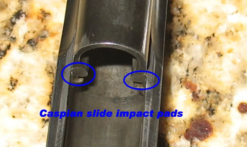
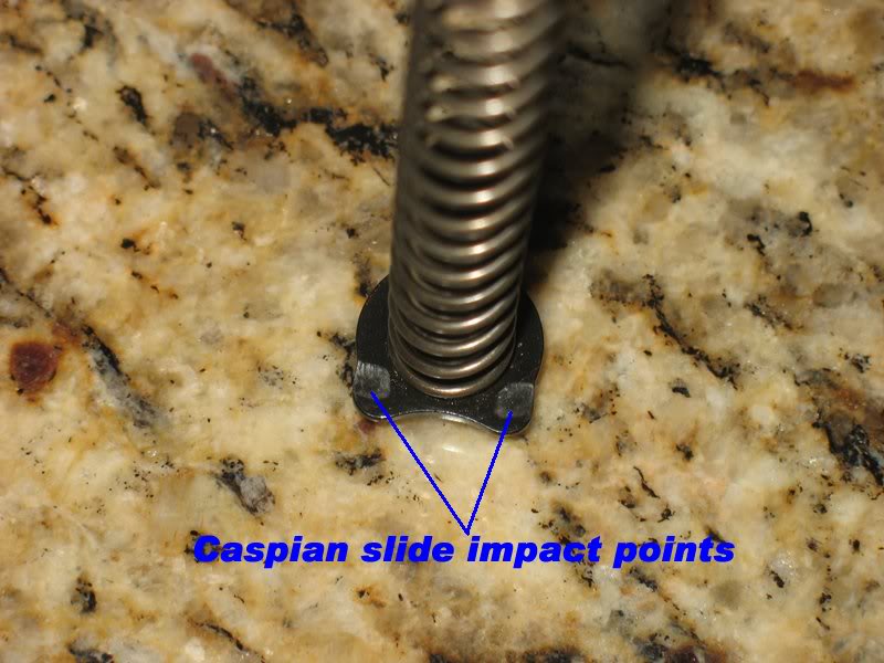
Plus they were .018 too tall being over the spec limit
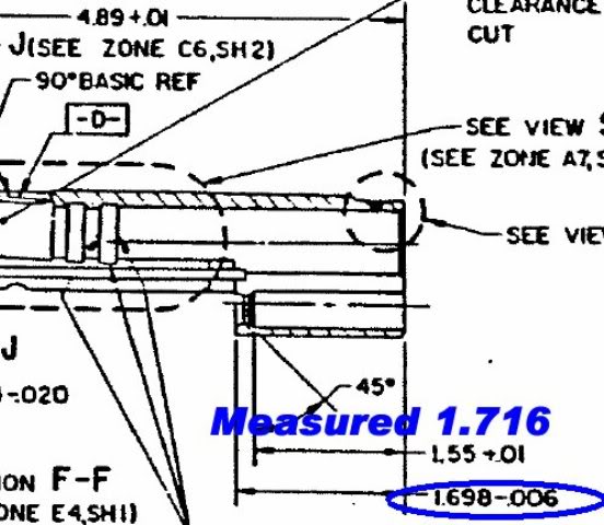
So I tooled the slide in my toolmakers vice and remove the offending material. Here is the result:
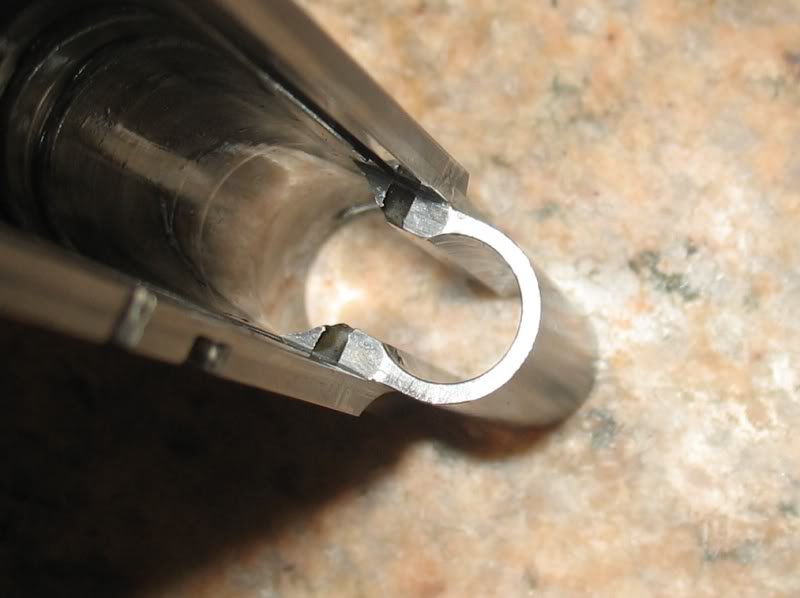
Now the entire contact surface measures 1.694-ish...within spec..
I receive the FLGR in blue that I ordered... blue FLGRs are rare... this one is a STI FLGR...
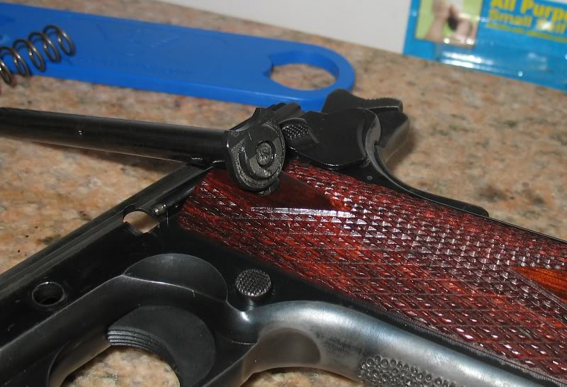
That has the same bevel over cut as my Colt Lightweight Commander FLGR... go figure...
But it sits nice and square to the new dust cover impact surface:
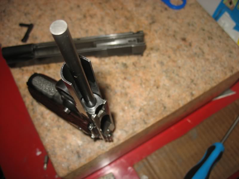
The recoil STI spring plug was on back order so I used a Wilson Combat plug I had laying around.
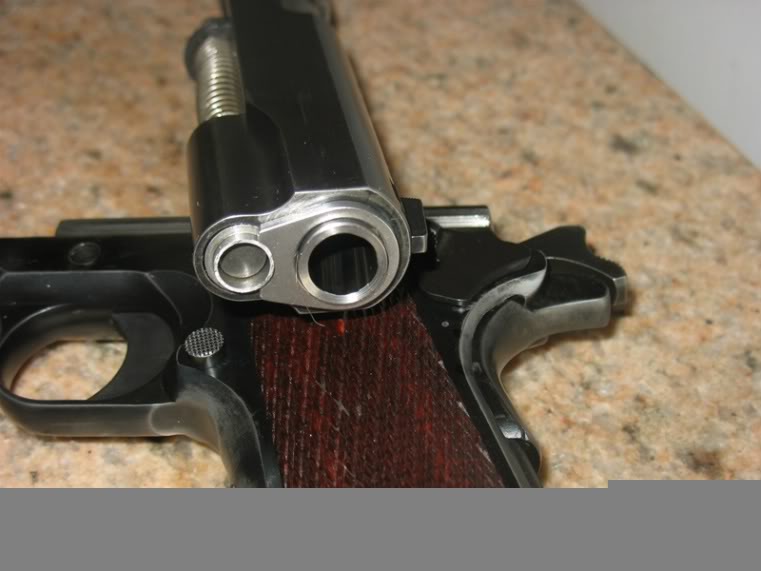
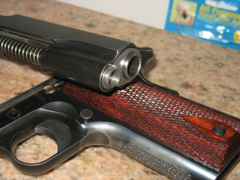
I kinda like the stainless plug....it accents the stainless barrel bushing....
I like being able to remove the top of the pistol in one piece:
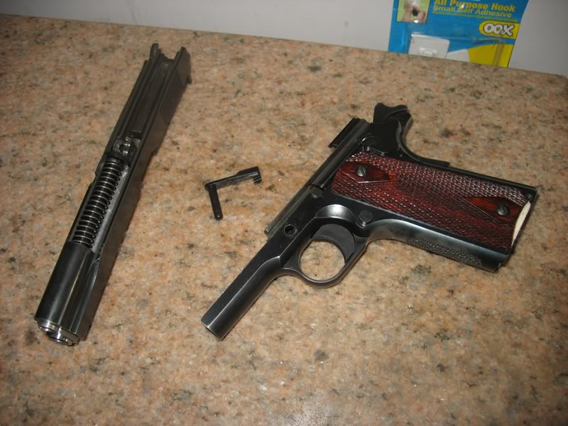
I believe that this style FLGR should eliminate any guide rod rocking because the end of the rod is supported by the plug...
It occurs to me that if you have a 40 lb impact stopping the slide, agonizing over the difference between a 14 or 16 lb spring to match it to your loads may be a waste of time.
Agree, I checked the original numbers and found that I wasn't applying the correct ratio to 240g full scale measurements... the correct number is closer to 15g...
I intend to buy a 120g accelerometer and a 8KHz (compared to 240Hz) Daq... with fastener acquisition I hope to get closer...
Quote:
Have you compiled or could you compile a minimum list of the tooling one
would need to assemble a 1911?
A list of tooling that is dependent on what type part you want to fit.
I intentionally choose 1911 parts that required fitting because I wanted to learn the most from this build.
Tooling I bought:
1) Power Custom frame fixture to hold the frame while I beat (fit) the slide to the frame.
2) Brownells barrel lug cutter... because I choose a barrel that required this tool to fit the barrel.
3) Jeweler's files because I needed to remove material from things that didn't fit.
4) White Arkansas stone set because I didn't like the marks left behind by the files.
5) EWG barrel hood gauge because I wanted to accurately measure my barrel hood so that could it would properly fit to the slide.
6) A toolmakers vise because I wanted to hold a part to .0001 tolerance.
7) A toolmakers vise because I wanted to hole a part square to .0001 tolerance.
8) Drop indicator certified to .0001" so that I could measure stuff to .0001"
9) Granite surface plate so that I could hold the parts to .0001" to be measured.
10) Brownell's 1911 file set because the files fit the pistol.
11) Kart Easy Fit installation kit file because the file fit the barrel lug cuts.
12) Feeler gauges because you needed feeler gauges to measure stuff.
13) Pin Gauge set so that I could accurately measure hole size.
14) Gauge block set so that I could accurately measure gaps and slots.
15) Micrometer because I wanted to measure to .0001/
16) Digital calipers because I wanted to measure to .001.
17) Digital trigger pull weight gauge so I would set the sear spring to within 1-oz.
18) Other tools that I can't remember.
Just a short list of $500 worth of tooling
I haven't worked on this pistol until recently...
I replaced the $10 MIM Springfield ejector with a machined Colt original GI profile one... I spent some time blending the back of the slide today... here is what it looks like so far:
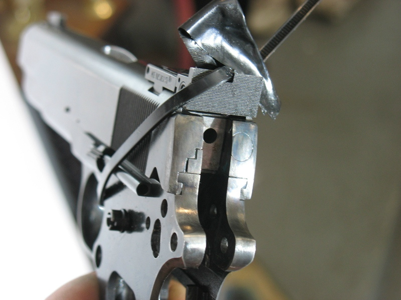
I shot her last weekend at a local indoor range... this was a 25-yards off hand five shot group at an 8-1/2 X 11 computer paper target... the front sight covered 1/3 of the paper width...
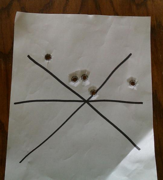
I need to practice more but at least she shows promise...