
Retrieved: November 06, 2011
Last Post: May 19, 2003
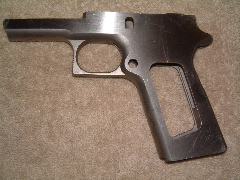
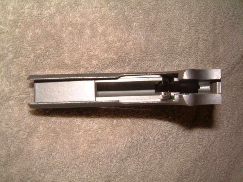
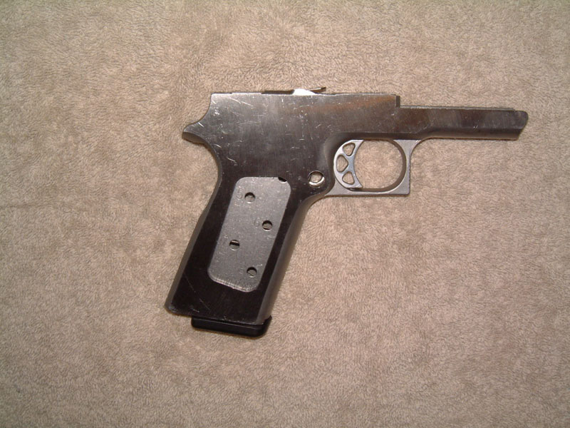
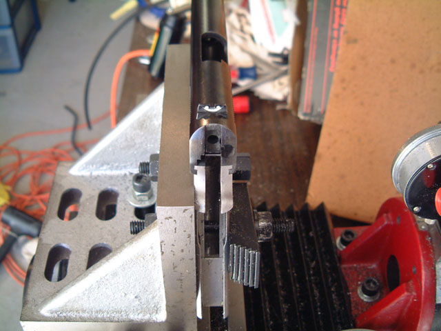
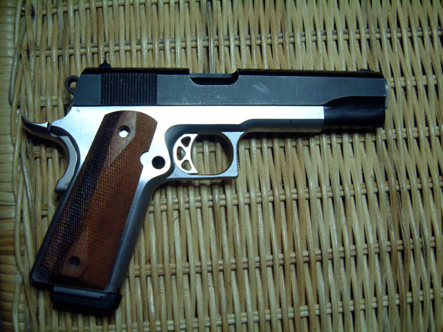
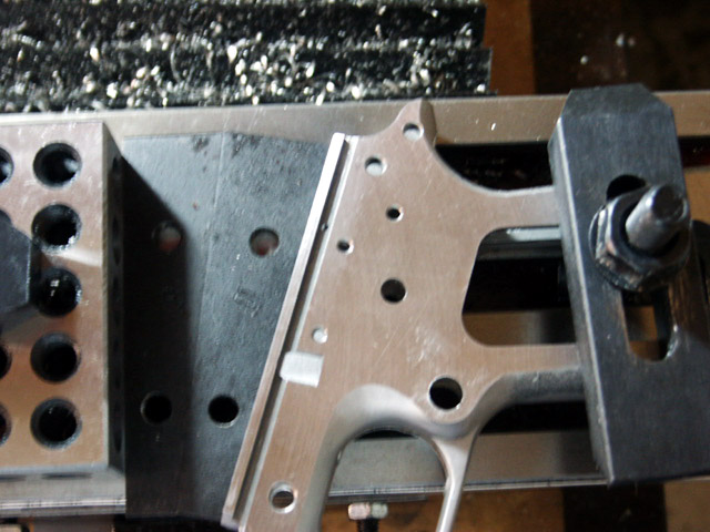
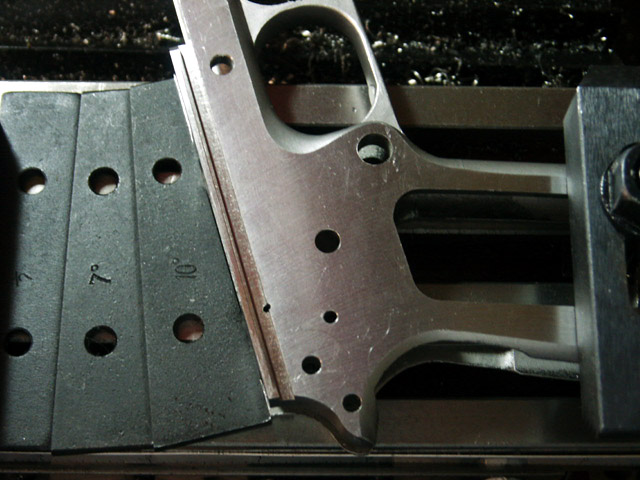
As you can see from the pictures, these have had 4 operations performed. The left and right sides have been surface ground down to a proper finished max dim. of .762", and the minor and major diameters for the mag catch hole were milled. Everything else appears to be as cast.
As I progress, I will post additional pictures, and such.
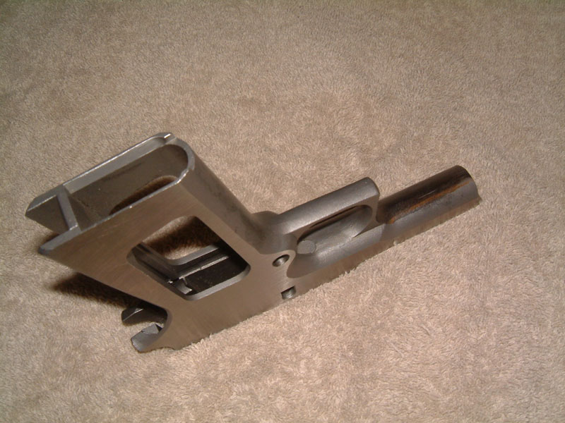
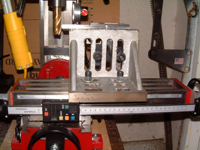
My plan is to use the angle plate for the majority of operatons. I will be using 1-2-3 blocks under the dust cover and in the middle of the grip area when drilling the horizontal holes.
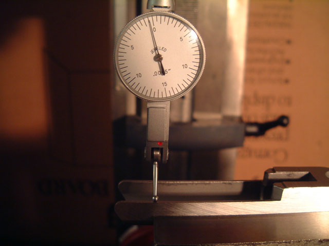
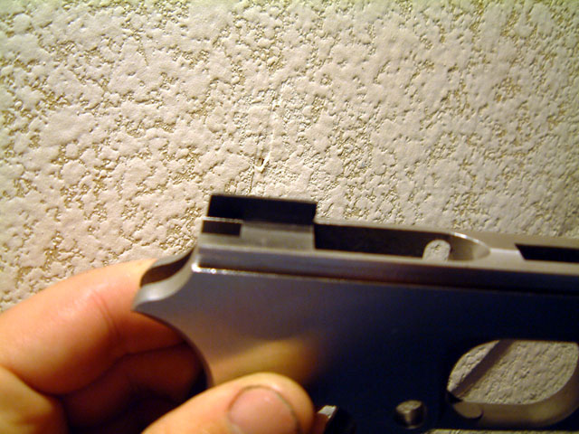
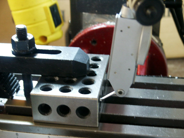
I clamped the frame to the angle plate, and indicated off of the top of the dust cover with a DTI mounted in a bridgeport type spindle arm. The dust cover seems to curve up a few thou in the 3/4" of an inch from the end, so I didn't indicate all the way out to the end. Surprisingly, I got within about a 1/4 thou, so I called it good.
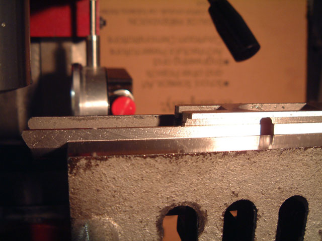
Here's what I ended up with after cleaning up the top deck. I am using TiN coated HSS endmills, and was able to achive a really nice finish on this cut (much better than I was expecting.) I used a 3/4" end mill, and took half wide passes.
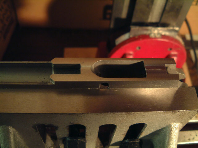
The frame is .762" thick, so the rail slots will go in .067" from the side.
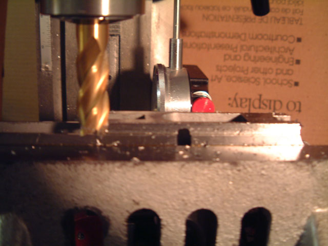
First task was an edge find to get the ball rolling.
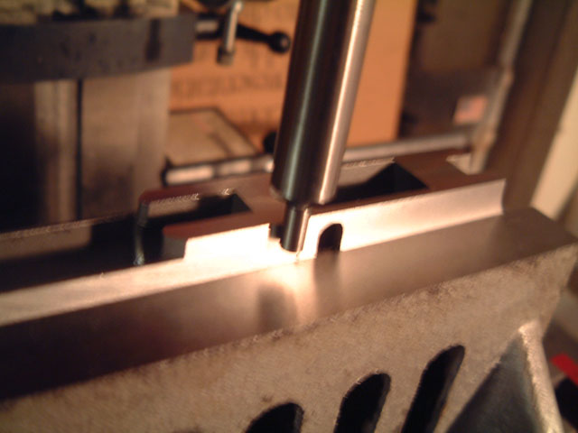
I am using a 1/16" HSS key seat cutter, and taking .015" passes. I've got DIs mounted on the Y and Z axis. I touched the bottom of the cutter to the top of the frame, and drop down .1675" for the first pass. The rails will be going below the level of the dust cover top, so the second pass goes all the way to the end.
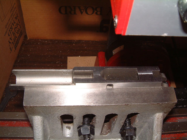
This is the left side finished. The cuts are considerably smoother than the picture would indicate.
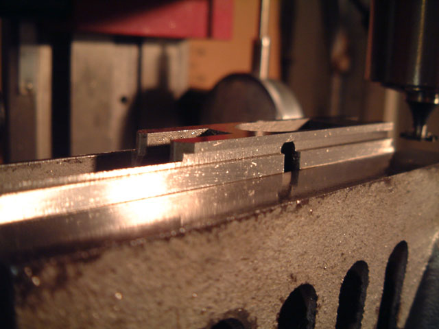
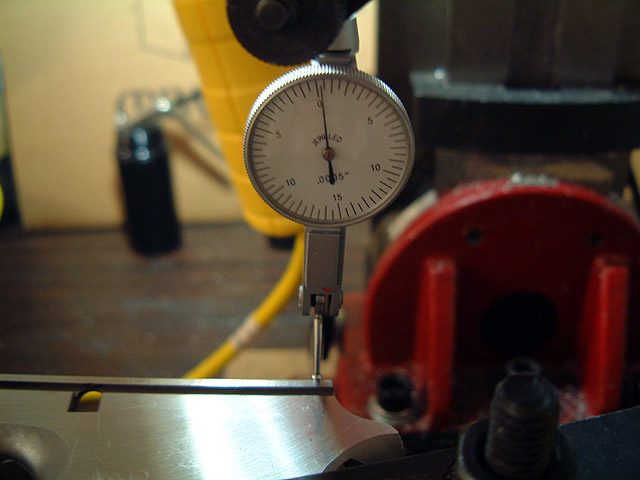
Next the top rails get shaved .0055" on each side to bring the width down to .751"
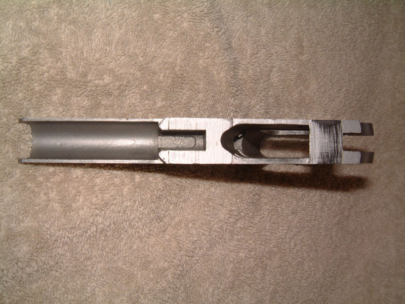
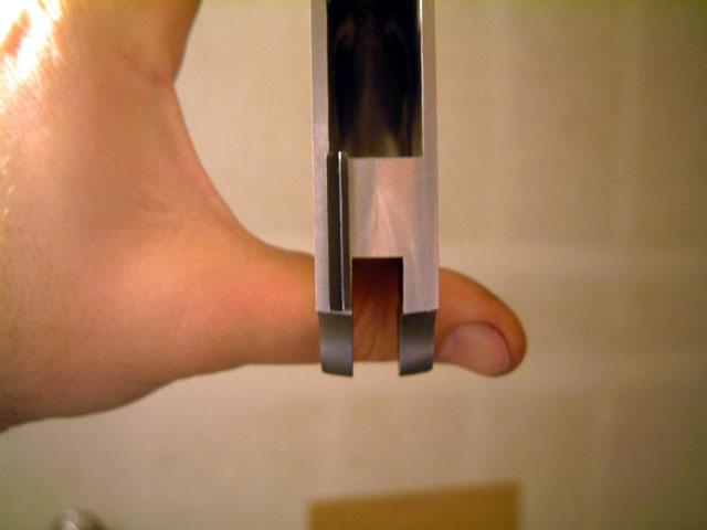
Here's a picture of the rails from behind.
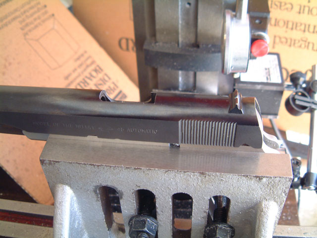
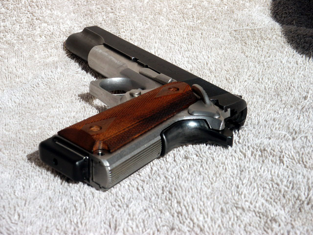
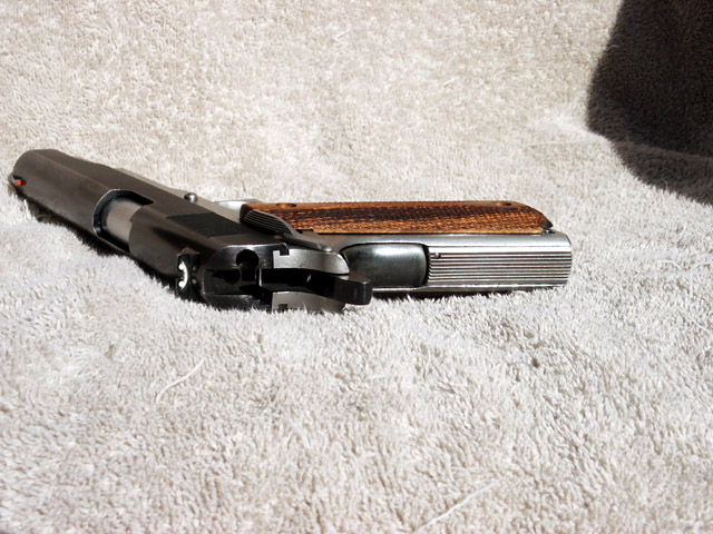
And here are a couple of shots showing a trial fit of a slide. As it turns out, the fit is just what I was looking for...I can push the slide on with heavy hand pressure. There should be just enough material to get a wonderful running fit after filing and lapping the frame.
First I centered out on a 5/16"(.3125) rod placed in the right hand side of the mag catch hole. And subtracted out .100 for half the edge finder, and half the drill rod for a total of .2562".
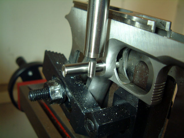
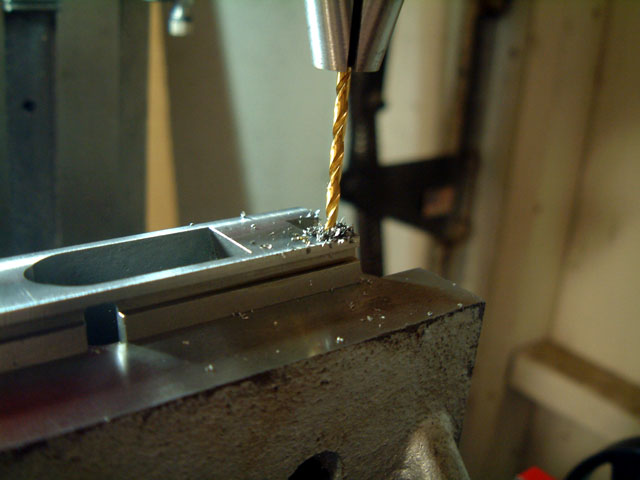
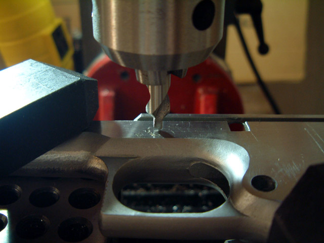
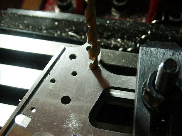
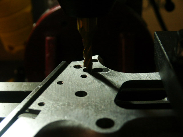
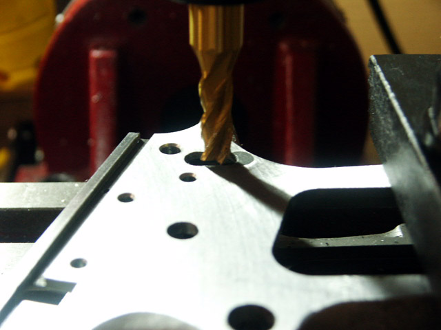
Next, I found the right side edge of the top rail, and proceded to center drill the two holes for the ejector. The front hole is .148" from the edge, and 1.198" from the center of the mag catch hole.
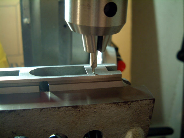
The second hole is located .133" from the edge, and .585" back from the first.
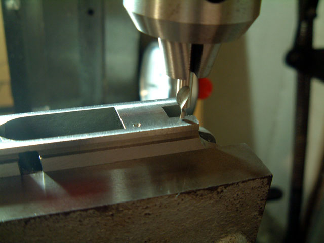
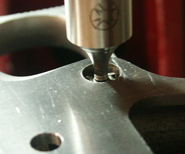
The final diameter for the rear hole is .0965, so I drilled it next using a #41 drill bit. I drilled this one down .250"
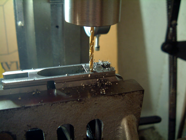
Back to the front...I drilled this last due to vertical limitations of the mini mill. I changed over to a 1/8" collet, and drilled this with a 1/8" drill bit to a depth of .330"
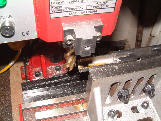
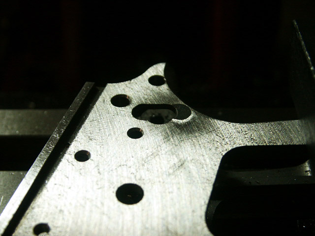
My final operation for this setup was to trim the dust cover.
I used a 3/4" four flute end mill, and trimmed down to 3.859" from the center of the mag catch hole.
This last pic is me trial fitting some parts before drilling the rest of the holes.
Dogbert, I'm a little confused as to what was done on the 40% when you
recieved it.

Is that the 4 operations you were talking about? (mag button hole, surface
ground, etc)
The four machining operations that appear to have been performed on the raw casting are surface grinding on both the left and right sides, and the two different diameter holes for the mag catch were milled.
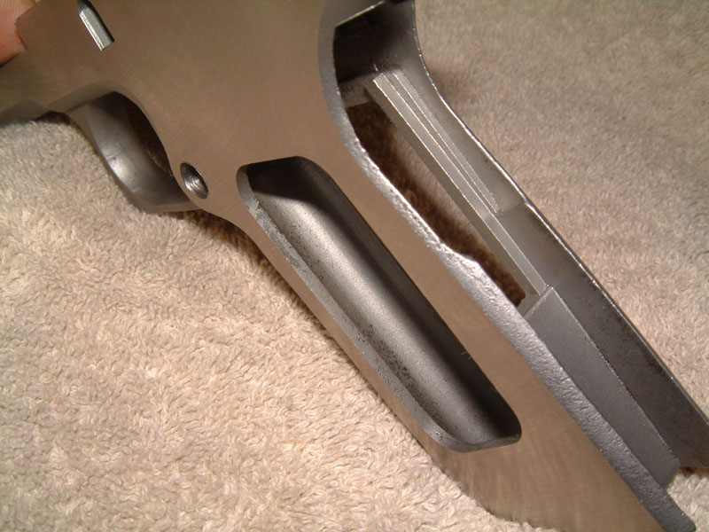
I think it is important to keep in mind that these are castings, and therefore have many areas that would otherwise need to be machined away from a forging or solid casting (the magwell being the most prominent of these areas) already opened up without machining.
MSH slots need to be cut, and the web between the mag well and the MSH needs to be thinned out by about half before a MSH will fit.
For the mag catch slot, I will be clamping the frame to a 1-2-3 block, mounting the 1-2-3 block into the swivel base vise, rotating the vise a hair over 17 degrees counterclockwise, centering on the mag catch hole, and then cutting the slot with a 7/32" end mill. While in this position, I will also cut the interal catch slot with a .050" thick keyseat cutter. The kidney shaped hole for the safety nub will also be cut in a similar fashion.
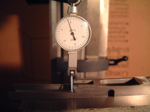
I then indicated across the top edge, with the DTI, to get proper alignment with the mill
And finally a center find on the mag catch hole to set the zeros.
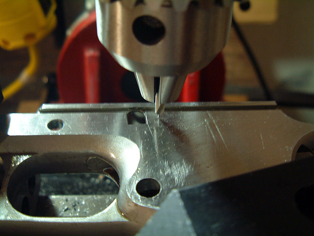
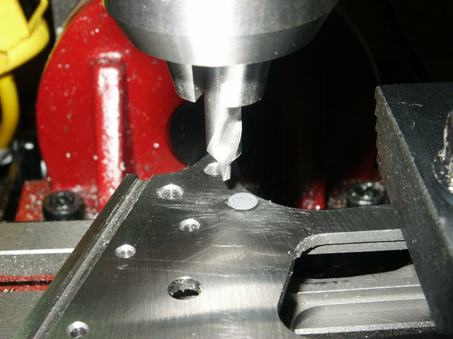
And then up 1.095" and over 1.193" for the slide stop hole. I drilled first with a center drill, and then followed up with a #8 drill and then a #7 (.201) drill.
After finding that my slide stop was still too tight, I reamed with a 13/64"(.203") reamer, and ended up with a nice snug fit.
Finally I chamfered the hole with my center drill, and zeroed out the DRO's, as all of the following holes are referenced from this hole.
I drilled all holes with a center drill, drilled with one size under, and them reamed to final size if a reamer was available, and then chamfered with a center drill.
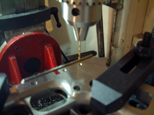
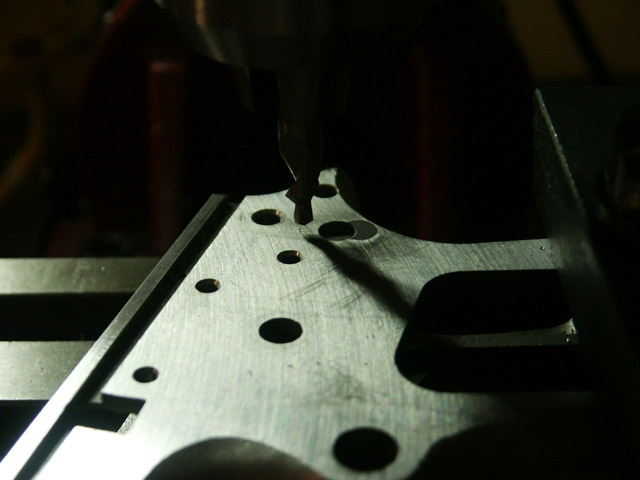
The front plunger tube hole is up .076" and over 1.402". Drilled with a #42 DB, reamed to 3/32", and chamfered.
The rear plunger tube hole is up 0" and over 2.204", and identical to the front.
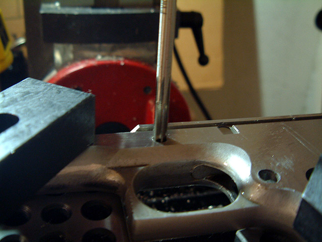
Next I drilled the ejector retaining pin hole. I was not happy with the results (I'll elaborate later) of drilling this hole from the left side, after drilling the front vertical hole for the ejector. Instead, I would recommend either drilling this hole first, and then doing the vertical holes for the ejector legs later, or drilling this hole from the right side of the frame to the left.
Regardless, I drilled this hole with a 1/16" DB, and located it up .2795" and over 2.3285"
The hammer pin hole is up .016" and over 2.973. Drilled with a #23 DB, and reamed to 5/32"
The safety pivot pin hole is down .210" and over 3.368". Drilled with a #23 DB and reamed to 5/32"
The sear pin hole is down .252" and over 2.602". Drilled with a 7/64" DB, and redrilled with a #34 DB.
Top grip screw hole is down .431" and over 1.937". Drilled with #3 DB and reamed with 7/32"
Bottom grip screw hole is down 3.309" and over 3.018". Drilled with #3 DB and reamed to 7/32"
And finally the MSH pin hole is down 3.595" and over 3.750". Drilled with #23. Redrilled with #22.
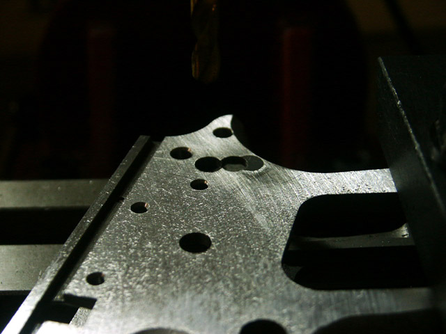
Here's a shot with all the holes drilled
And another fitting shot(I like to check frequently that I am not working on something that is already dead.)
I still have the following left to machine:
Trim the bottom of the magwell
Sear spring retaining slot in the back strap
Feed Ramp
Disconector hole through the top
The little slope at the top rear of the frame
The crescent cuts behind the trigger
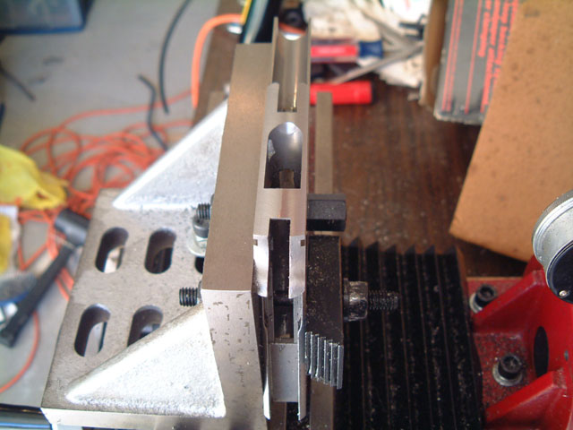
Next up was the kidney shaped safey slot, and the mag catch slot. Both required angular offsets from horizontal, so I decided to use a 1-2-3 block clamped to the left hand side of the table, combined with angle blocks for the offset. The block was aligned with the mill using a dial indicator. I was originally going to use the swivel base vise for this, but later realized that this whould require a lot more aligning and realigning.
The safety slot is 18§ off vertical, so I used a 10§ and an 8§ block to set the angle from the top of the frame.
And now for the big screw up. The center of the bottom radius for the slot is given on the blueprints as being over .465", and down .197". However, the horizontal measurement is given with the frame rotated at 18§, and the vertical is given with the frame at 0§. I didn't notice this until after it was to late. The result of going down .197" with the frame rotated 18§, was that the hole was too low. What a pissa', eh?
Anyway, I only have one of these castings to work with, so I am going to make the best of it (BTW, If anyone actually has one of these 40%er that they want to sell, I would be interested in buying it from you). I probably could have just left the extra space empty, and the safety would still work fine, but instead I decided to fill it in with a JB Weld type putty...putting this pistol 1/8 of a gram closer to a Glock, and redrilled the hole. At some point it might be worth it to have someone weld this up, and rework the slot.
As it turns out, with the frame turned 18§, the center of the hole should be .465" over, and .066" down from the safety pivot hole. I center drilled, and then drilled with a #3 (.213") drill bit.
The slot is .404" long, so we move up .191", and drill the top hole.
I then cleared out the middle with a 3/16" end mill.
Last is the perpendicular notch that allows the safety to be inserted. This is offset forward .0385" from the center of the main slot, and down .046" from the center of the safety pivot hole. I used a 1/4" four flute endmill, and plunged it down to create the notch.
Next was the mag catch retaining slot and mag catch slot. This is offset 17§ 30' from horizontal. Not having a 1/12§ angle block, I opted for using the smallest I have which is 1/2§. In hindsight, I would probably just stick with 17§. In this shot you can also see the poor result of drilling the ejector retaining pin hole from the left side, rather than the right.
I then did a center find on the mag catch hole, and using a 1/4" x .050" keyseat cutter, touched the bottom of the keyseat cutter to the top of the frame, and dropped down .110". I then cut in .053".
Next was the mag catch slot. From the center of the existing hole, I went back .227", and drilled with a 7/32"(.2188") drill bit. I then cleaned out the remaining middle portion with a 7/32" end mill. For some reason, I didn't take any pictures of this step, sorry.
A wee bitty bit of mathematical trivia for you, Dogbert... You did the catch
lock slot exactly right. Dunno where you got 1/12 of a degree from... 17 deg
30' is seventeen degrees, thirty minutes, or 17.5 degrees. Exactly on the
money.
You are correct Raven, there are 60 arcminutes in a degree. At the wee hours of the morning that I was working on this item, I somehow got it stuck in my head that there were 360 minutes in a degree. As you said, it all worked out in the end.