Retrieved: January 13, 2011
At some point I decided it would be a good idea to build a 1911. I wanted a gun suitable for lugging around the wilderness, but can't hit squat with a double-action revolver. More importantly, though, it sounded like fun. (I'll pause while those of you who have built a 1911 finish laughing.)
Given that this gun would be seeing potentially inclement conditions and, worse yet, unskilled assembly, choosing precision parts seemed inadvisable. After all, "top of the line" is close friends with "top dollar," and I didn't want too many of my top dollars resting under the surface of a file-- especially not one held in untrained yet enthusiastic hands. I decided to go with a Sarco parts kit, which is about as inexpensive as it gets. This would be paired with an Essex frame. The Essex frame is not the cheapest frame one can buy, but they have a good reputation. More importantly, they come with the ejector, plunger tube, and grip screw bushings already installed. I didn't anticipate having to touch the frame, so splurging a few extra dollars there wouldn't be too risky. The rest of the gun, though, would come from Sarco's grab-bag of no-name or USGI surplus parts.
The problem with going cheap is that one runs an elevated risk of parts being out of spec. Potentially, I was looking at a lot of headaches and hand- fitting. This didn't bother me: Part of the appeal of building the gun was the process itself. If everything fell together as if I had just detail-stripped a factory gun, there wouldn't be much process at all. On the other hand, I didn't want to find myself up a creek without a lathe.
So it was that with equal parts trepidation and enthusiasm I filled out the Sarco order forms and dropped them in the mail. It would be several weeks before I would discover what the future (and UPS) would bring.
You, however, can just click any of the links on the left to find out right now.
Obligatory Disclaimer
Before moving on to the gory details, I have to mention that I'm not a gunsmith, nor do I play one on TV. In one conversation about the finished gun at the range where I was testing it, the fellow with whom I was talking asked me what I did for a living that gave me the skills necessary to build a 1911. I had to tell him, "nothing." I'm a computer programmer by trade with next to no metalworking experience. Prior to building this gun, I'd never even taken a 1911 down beyond field-stripping. This entire project has been a learning experience, and the only way you learn is by making mistakes. Where possible, I've identified the mistakes I made in the hopes that others might avoid them, but it's almost certain that there are quite a few errors that haven't been caught. (If you spot any, please let me know.)
Even where I didn't get things wrong, the techniques, tools, and materials used are usually far from ideal. This account is neither a primer nor instructional materials, except to the extent that it illustrates what not to do. I put these web pages together because building a 1911 was very enjoyable and I wanted to share the experience with others. Also, I goofed up with sufficient regularity to provide at least some amusement to those who know what they're doing.
Enjoy.
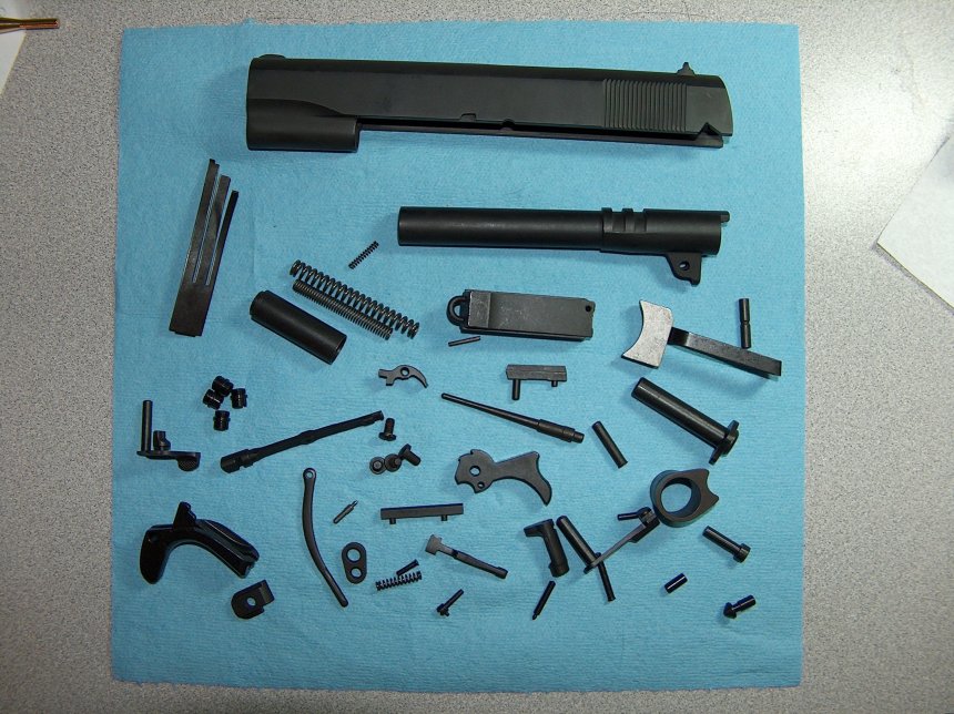
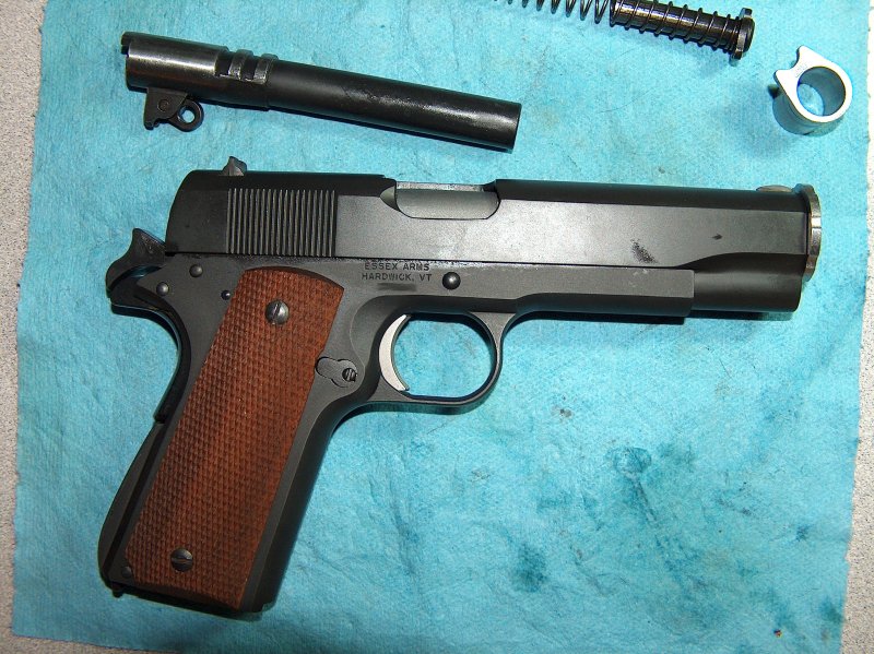
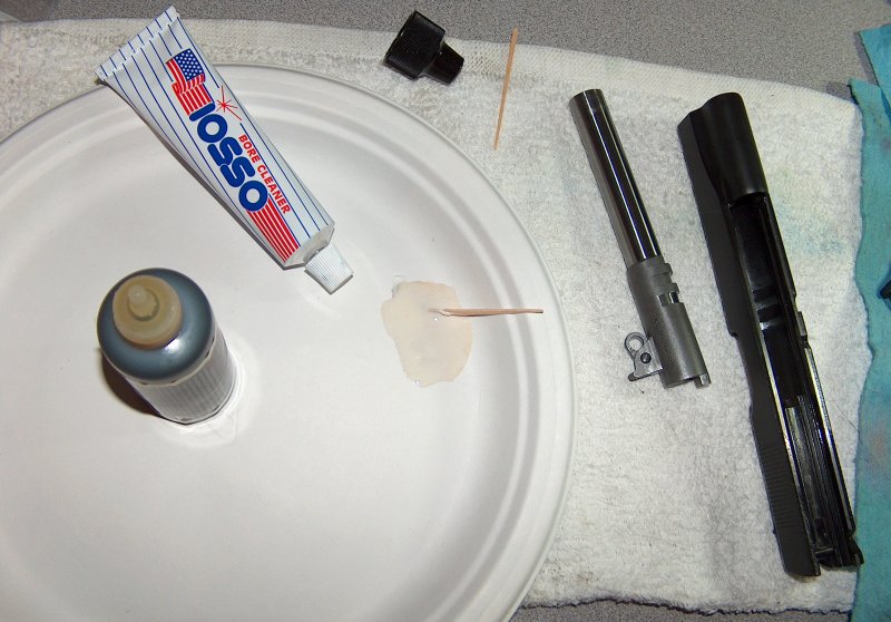
At least, that's what it looked like spread out on my desk. Part one of my shipment arrived, so I wasted no time prying open the box and arranging its contents on a convenient shop towel. (You'll notice that shop towels figure prominently in this account.) It made for an impressive display of itty-bitty pieces of expensive metal I would be responsible for assembling into something that contained 20,000 PSI of pressure in order to throw half an ounce of lead at 80% the speed of sound.
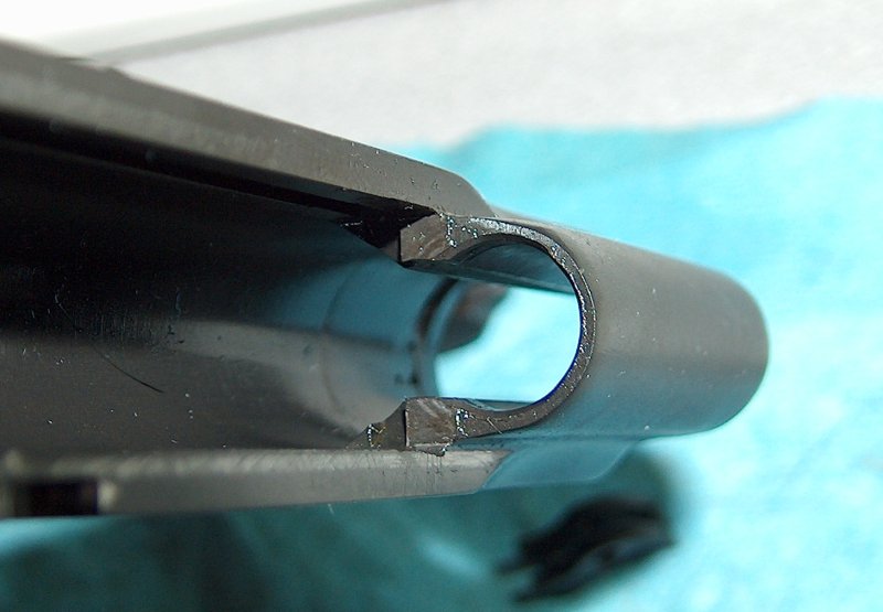
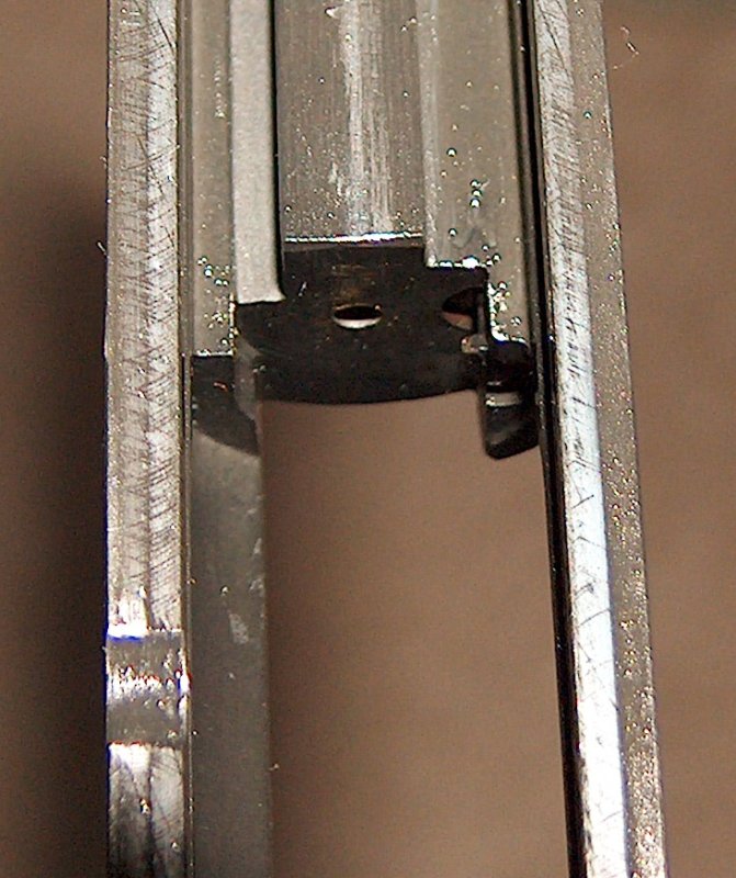
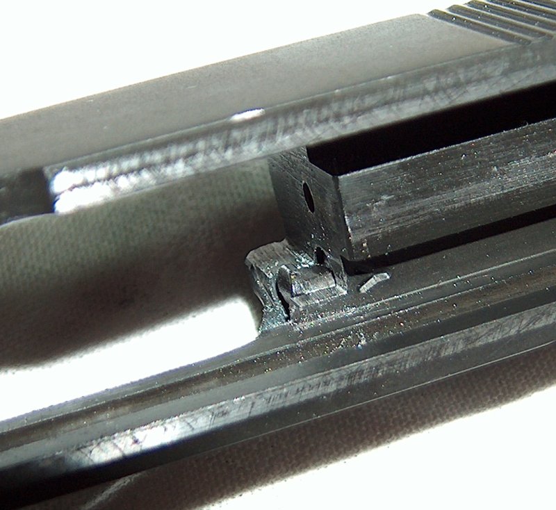
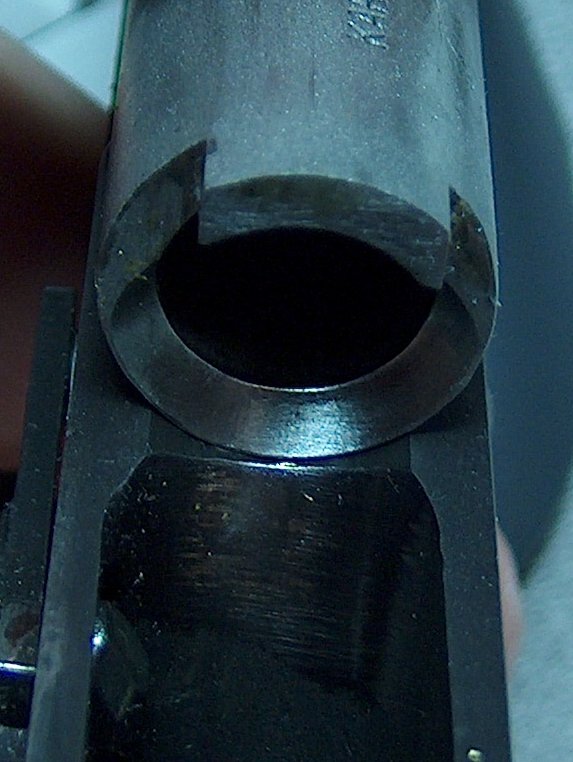
As it turned out, I was missing a piece; see if you can spot it. If not, all is revealed later. The missing part wasn't the only thing wrong with my order: Close inspection of the slide lug nearest the barrel hood showed what looked like either spalling or tool chatter. Although the problem might have been merely cosmetic, I didn't like the ramifications of finding out otherwise.
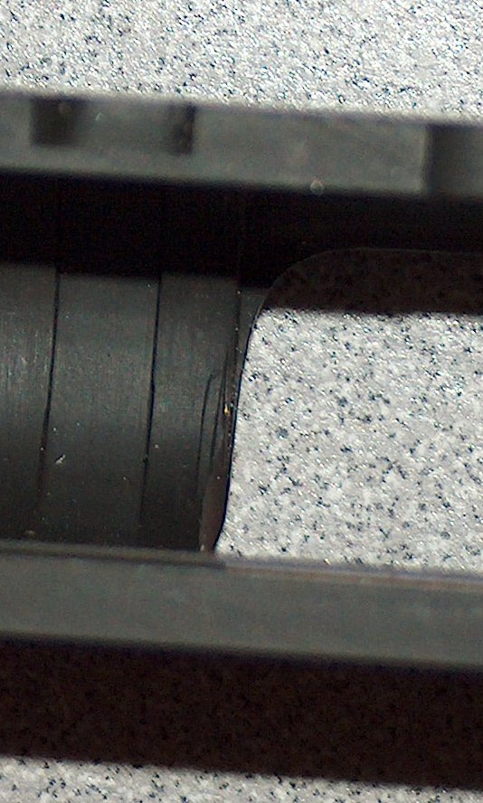
No way I'm putting 1.5 tons of pressure on that.
Disappointed, I acquired an RMA number from Sarco and boxed up the slide for return. The frame was still in transit, so there wasn't much to do until either it or the slide made its way to me.
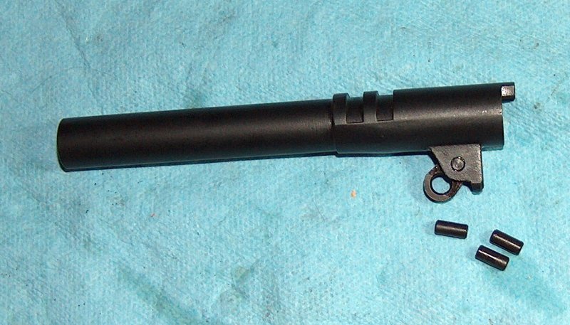
While I waited for the slide's RMA to be processed, I looked over the parts some more. The barrel left quite a bit to be desired; the chamber area was pretty rough, featuring a casting line along the bottom. The lower lugs had seams or flanging along the outside of the lugs. Finally, there was a burr inside the lugs that prevented the link from enjoying a full range of motion. It would definitely need some cleanup.
So this is what a $40 barrel looks like.
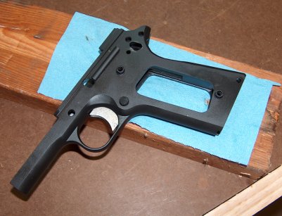
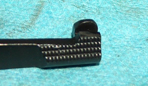
On the bright side, I was happy with the styling of the parts, even if a few of them were a little rough around the edges. Although I requested the arched mainspring housing with lanyard loop from Sarco, the inclusion of a spur hammer, checkered slidelock, and GI-style safety (visible on the left in the top photo) were pleasant bonuses, as they would contribute to the classic look I hoped to achieve.
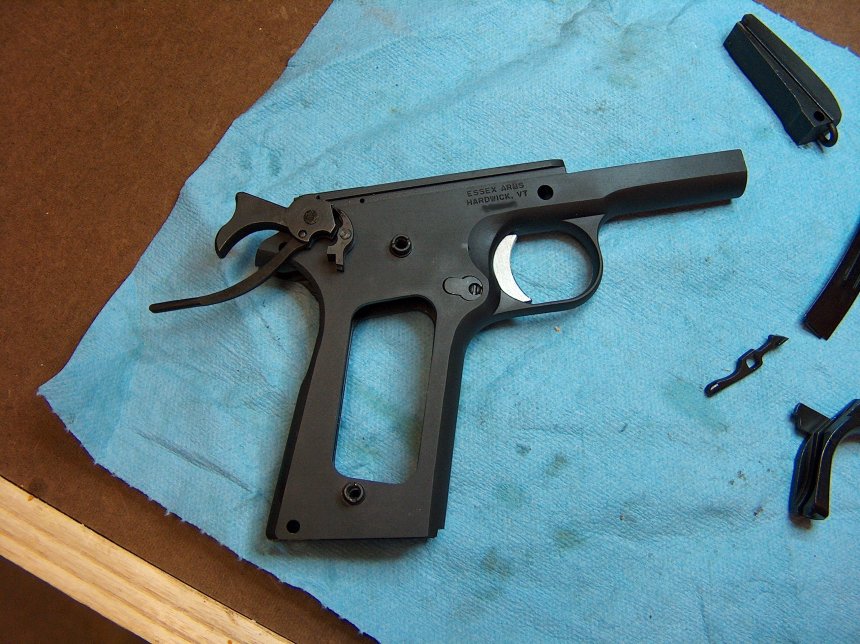
Before I got a repaired slide back from Sarco, my frame arrived. I had it shipped to Survival Arms in Bellevue for transfer because they have the best local transfer fees, friendly staff, and they're located next to a school for Krav Maga, the Israeli martial art; there's nothing like the sound of people beating the crap out of each other to lend delightful subtext to the purchase of firearms. The frame itself looked good and I wasted no time putting it on a shop towel and testing all the larger, external parts for fit.
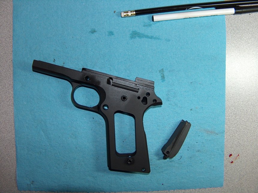
We all have to start somewhere.
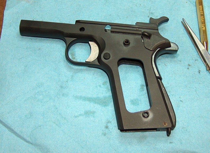
Note the bloodstain on the right in the above photograph; this was produced when attempting to fit the mainspring housing (also in the above photograph) to the frame. There was a small burr on the left side of the housing that bound in the frame, causing it to get stuck. I brilliantly applied the always- appropriate principle of exerting large amounts of force with my bare hands. This worked, of course, but at the cost of suddenly whipping my finger across the sharp groove in which the housing sits when the housing released. Once again it is proven: Guns hurt people.
After hurriedly cleaning blood off the frame to prevent rust, I bandaged my finger and fitted the mainspring housing. Even after filing down the burr, the housing would still get stuck. (This time I wisely used a pencil to tap it out.) The solution turned out to be filing down the sides of the housing until it went in without too much coaxing. It's worth noting that filing to fit is not a linear progression: The closer you get to a fit, the less that should be taken off between test fits. I cold-blued the exposed metal on the mainspring housing and moved on to testing the other parts' fit.
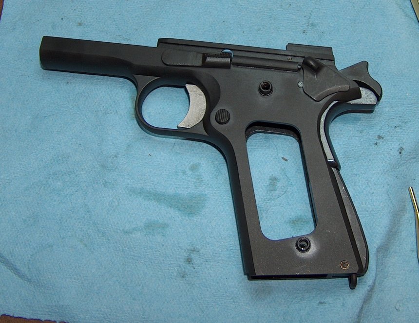
The trigger fit into the frame, although it took some coaxing and oil at first. No such problems with the grip safety, which fit perfectly. The thumb safety also fit well, although it didn't have the full range of motion up and down. I assumed at the time it needed the internals added in order to move properly; as it turned out, the safety just needed to be fitted. Finally, the slide release dropped right into place, providing no hint of the monkeying around that would be required to make it work properly.
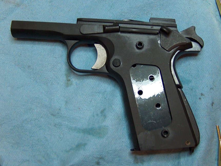
Before I called it a night, I tried to put the brown plastic GI surplus grips onto the frame. No dice. While the left side fit fine, the right side refused to go on because the bushing holes were too far apart. The plastic grips from a Springfield Armory Mil-Spec dropped right into place, so the right grip panel itself was to blame. I rendered it blameless with a needle file and two minutes' worth of work elongating the bottom of the lower bushing hole. Just this small amount of work with the grip panels left my hands greasy with ancient cosmolene, so I took a brush and some mineral spirits to the grips. The mineral spirits took both cosmolene and paint off the grips, as well as residual gunk off the brush: Everybody won. While the grips themselves have clearly seen some use, they don't look too bad on the gun and have a great deal of character.
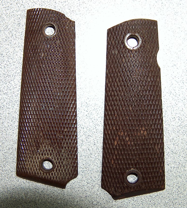
Get a grip.
With the grips fitted, all the frame externals were more or less complete. The next logical step would be to fit the frame internals, which I expected to be far more challenging.
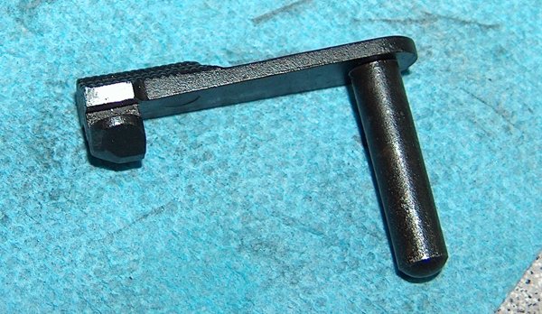
As mentioned earlier, Sarco's parts kit reached me without a piece. As I discovered while trying to put together the frame's internals, this piece was the hammer strut pin. On reflection, it's entirely likely the pin had arrived with the other parts but was now either embedded in carpet fiber, mouldering inside a vacuum cleaner bag, or passing through the digestive system of a cat.
Another issue I had was with the barrel's link pin. Unlike the vanished hammer spur pin, I actually still had this particular pin in my possession. Unfortunately, this did me little good because the pin wouldn't even start into the barrel lugs. I understand some effort is required to fit the link pin, but either the pin was oversized or the hole in the barrel's lower lugs was too small. Before widening the lug hole, I felt it would behoove me to try to find a smaller link pin.
Fortunately, a gun show happened to be in town, so I stopped by. One of the tables featured trays of 1911 parts, so I picked out a few of the hammer strut pins that looked like they'd seen the least staking in their lives. I also picked up some link pins in various diameters. Finally, I also acquired a set of 1911 grips in mountain ash, which turned out to look less than attractive against the blued frame, which is why you won't be seeing any pictures of them attached to the gun.
The first thing I did was to assemble the mainspring housing. This turned out to be about as easy as putting a baby back into the womb from which it has issued under enormous spring pressure. There are three schools of thought on how best to keep the mainspring compressed while fitting the retaining pin into the housing:
Hammer a nail with a head of the appropriate diameter into something stationary (e.g. not a cow), then just hold the mainspring housing in one hand, use the head of the nail to compress the spring, and insert the retaining pin with your free hand. This method is simple and foolproof, so naturally it did not occur to me and I was forced to fall back on the other methods:

Mild sarcasm not shown.
With the mainspring housing assembled, I moved on to attaching the hammer strut to the hammer. I double-checked to make sure that I was attaching it correctly, but I needn't have bothered; the pin just slid in with a light friction fit and could easily be pushed out with a punch. It looked like the pin had been staked at some point in its life, which would probably have to happen again, as a loose hammer strut pin can drag against the frame or even cause hammer bind. For the time being, though, it would suffice.
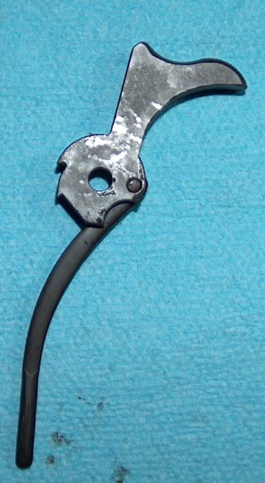
The hammer struts its stuff.
With the hammer set up, it was time to cram everything into the frame. The trigger goes in first and is held in place by the magazine release, which is an amazingly clever piece of engineering. The sear and disconnecter follow; these are really finicky to put in place, but it gets easier after you do it a couple hundred times. Add the sear spring on top, then hold the grip safety in place with the shaft of the thumb safety so that the slight rim on the bottom of the grip safety fits under the mainspring housing. Consequently, if you put the mainspring housing in first, the grip safety won't fit. Don't ask how long it took me to figure that one out. With the mainspring housing and grip safety held in place with one hand, the hammer can be gently pushed into place with the other hand, and the hammer pin dropped in with the third hand. Execution of this process with fewer than three hands is left as an exercise for the student.
Assemble frame. Repeat five million times.
You may have noticed that in the photo above, the mainspring housing pin is not inserted. I had some trouble getting it in. Okay, I had a lot of trouble. My reading had indicated that this could be pressed in, but a great deal of pressing merely left my thumb looking as though it had been attacked by a small but determined octopus. Some sort of block was required to get that dang pin in, but for now the metal handle of a needle file sufficed to hold the mainspring housing in place while performing function tests.
As mentioned earlier, I was still waiting on a slide, so function tests had to be performed carefully. Dropping the hammer without a slide in place to catch it can peen the frame, so I'd have to keep a good grip on the hammer while testing the safety mechanisms. Despite this constraint, things went well. The trigger tripped the sear, but only if the disconnecter was up. Depressing the grip safety allowed trigger travel, and not depressing it blocked the trigger bow. The manual safety...didn't work. The channel between the wide plate of the safety that is visible on the exterior of the gun and the lug that blocks the sear was cut too shallow, which prevented the entire safety from sliding up. A few minutes with a file fixed that particular problem and I was able to confirm that the thumb safety blocked the sear.
All in all, a very productive evening.
In the previous chapter I was having trouble getting the mainspring housing pin to fit in and couldn't figure out if this was normal or not. Consultation with the sages who hang out on the M1911.org gunsmithing forum revealed that I was probably being a weenie and not applying enough force.
Okay. I can provide more force.

More force.
While I enjoy few things more than using a hammer to solve problems, it's possible to warp the frame if the mainspring housing pin is injudiciously driven in. To work around that problem, I grabbed a length of scrap 2x4 and drilled holes in the approximate locations of the grip bushings. It took a couple tries to get it right.
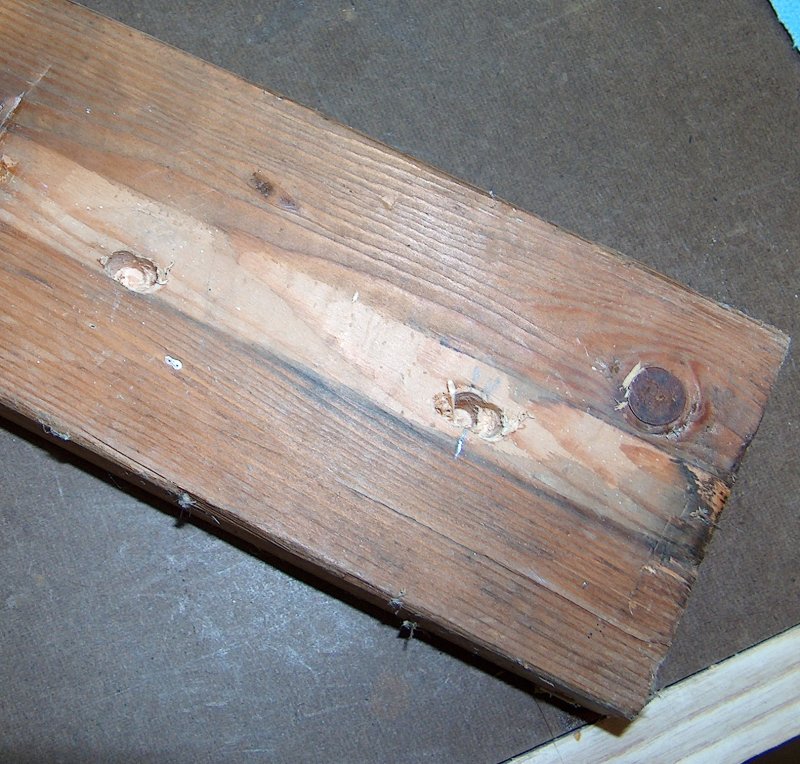
I got board with building a gun.
In order to prevent splinters and sawdust from getting into the gun, a shop towel was added. The final result isn't pretty, but it works.
Ad hoc block.
With the frame properly supported, it was the matter of a few minutes' work with a hammer and brass punch to insert the mainspring housing retaining pin. Remember how I mentioned last chapter that the grip safety has to be in place before inserting the mainspring housing? Remember how I also mentioned that it took me a couple times to figure this out? Yeah.
While driving out the mainspring housing pin in order to install the grip safety, I discovered that one more hole was required in the board so that the pin could have somewhere to go when being driven out. I drilled a small- diameter hole partway through the 2x4, drove out the pin, then promptly spent the next five minutes swearing and trying to get the tiny pin out of the tiny hole. (Note tweezers in next picture.) The hole was redrilled with a larger diameter, and this time going all the way through the board. Ultimately, this would allow the pin to be driven out, fall on the floor, and require five minutes of scrounging in the dirt, dead bugs, and decapped primers to find, but that's more user error than design flaw. For the time being, the frame was completely assembled, and I rejoiced by taking a photo of my work, which had nothing left out and no part of the frame forgotten.
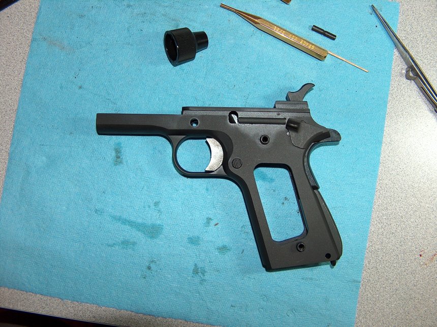
Yep, I forgot the plungers and spring. I discovered this when I went to insert the slidelock. Let's try that again.
Much better.
Now that the plunger tube was assembled, the manual safety did its thing, although it felt a little light. That could be fixed later; for now, I was just glad it worked without additional fitting. Having all the parts assembled in the frame meant that it was now possible to test the magazine release and slide lock behavior. This worked well: The magazine release locked and released the magazine, and an empty mag pushed up the slide lock with its follower. Hitting the magazine release caused the mag to eject like greased lightning, which was only appropriate, as the mag was greasy.
A MAGnum opus.
Sarco still hadn't gotten my replacement slide back to me, so I could procrastinate no further: It was time to dress the casting marks on the barrel's lower lugs and fit the link pin.
Having nothing further to do in avoidance of this moment, I decided to dress the lower barrel lugs. This operation was not to reshape them, but just to clean up some of the casting marks I had noticed earlier. I used a piece of 800 grit sandpaper wrapped around one of my small files to lightly sand down the high edges, after which I cold-blued the exposed metal. I neglected to take photos of the process, but you're not missing much, just some shiny spots on the lower lugs, which the cold-bluing erased.
Next up: the link pin. Previously, I had bought a selection of link pins at a gun show in the hopes of finding one with a diameter that at least pretended to fit through the appropriate holes in the barrel's bottom lug. Link pins are not supposed to just drop through the lower lug's holes, but the one that came with the parts kit wouldn't even start.
Fortunately, one of the link pins I acquired was narrow enough to permit wedging it into the hole, although more force would be required. This time, force was not provided courtesy of a hammer (darn it!), but by a vice. I used rubber bands to hold the link in place on the barrel, then padded my vice with a convenient shop towel, placed the lower lug into the jaws, and started gingerly turning the screws.
If you've ever seen that staple scene in submarine movies where the sub dives far beyond its rated capability and the hull makes ominous creaking and groaning noises while the submariners look about with expressions of apprehension, then you'll be familiar with the sort of noises a link pin makes when it is forced into position by a vice. I'm sure my expression was also true to canon. Fortunately, no depth charges were forthcoming and the link pin fitted into place without incident.
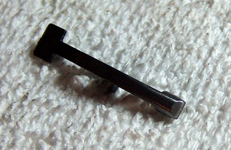
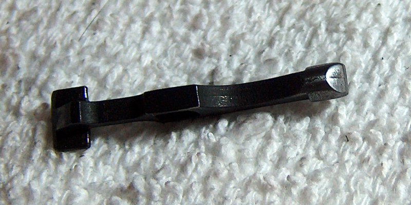
Missing link not found in this image.
The only fly in the ointment was the fact that the link pin would not rotate to full link-down position until I filed off a small burr between the two lugs. After that was fixed, the link appeared to work as designed. With the barrel's lugs dressed and the link pin inserted, I could make no further progress on the gun until the slide arrived.
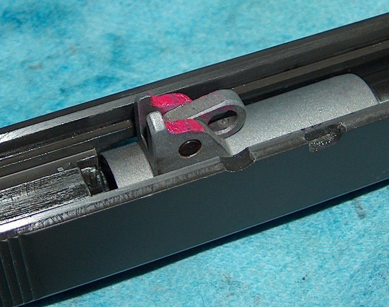
The replacement slide from Sarco hadn't arrived yet, but the desire to tinker was overpowering. The most compelling urge was the desire to feel the trigger pull, but without the slide to catch the hammer, this wasn't feasible. The next best option, though, was examining the parts influencing the trigger pull.
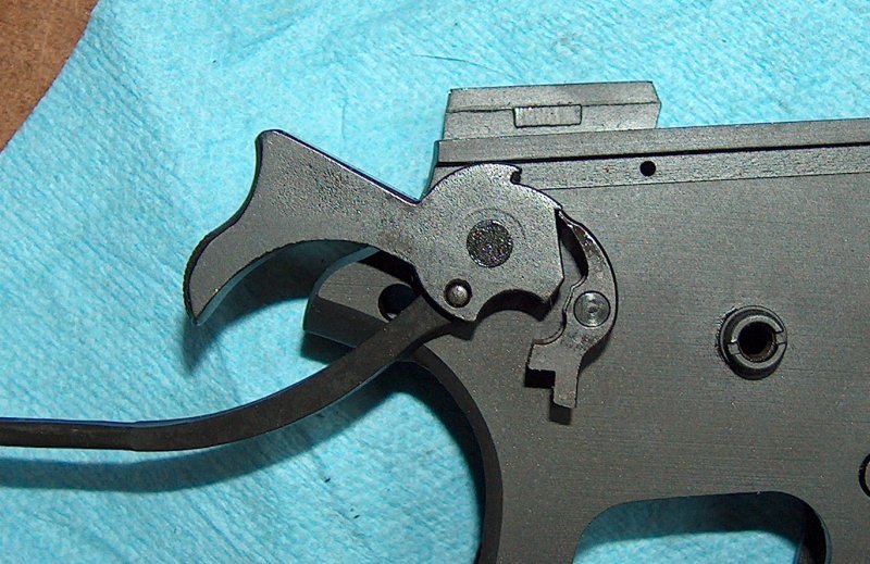
Most places that sell gunsmithing supplies sell special hammer and sear pins designed to pass all the way through the frame so that the hammer and sear's fit can be examined without requiring the ability to see through tempered steel. Possessing neither the ability to see through solid objects nor the special pins, I just used the standard hammer and sear pins. Because the pin wouldn't be supported through both frame holes, the positioning of the hammer and sear on the outside of the frame might be subject to some wobble. That was okay, since I was just taking a look at how the parts fit, not trying to get a Bullseye-grade fitted-by-microscope matchup.
On the outside looking in.
A closer look showed that the mating surfaces of the hammer and sear were
close but not perfect. The primary and secondary engagement surfaces didn't
mate up perfectly with their counterparts on the hammer. My guess was the
trigger would have some creep in it and might also be heavy due to the
mechanical disadvantage introduced by the imperfect fit.
Tamest picture of mating you'll find on the internet.
While I was at it, I decided to measure the lengths of the sear and disconnecter. According to Kuhnhausen, most Colt factory fit disconnecters measure between 1.287" and 1.290", but others "can exceed 1.310 inches in length." I guess mine was one of those others, as it measures 1.32" long. A long disconnecter is definitely to be preferred over one that's too short: Long disconnecters drag a little; short diconnecters can cause doubling or, worse yet, let a gun fire out of battery. The sear measured out to about 0.41" long, which is above Kuhnhausen's cutoff point of 0.395". The two parts seemed to work well together, but I would have to wait for the slide to confirm. Although I would probably have to take it apart again to fit the slide, I reassembled the frame for the practice, then resumed restless pacing. Where was the slide,
At last it had arrived: The replacement slide I had been waiting for since A Million Little Pieces showed up on my doorstep. Wasting no time, I did what any red-blooded American would do: tried to put it on the frame. The slide-to- frame fit was initially so tight and rough that I thought filing the rails would be required. Fortunately, I applied prudence and oil before applying a file and managed to coax the slide at least as far as the ejector, where it hung up. That made sense: Too high of an ejector could always be filed down to fit the channel.
Yanking the slide off, I assembled its components. The barrel bushing and extracter, like the slide on the frame, were very rough and tight until coated liberally with oil, after which they slid into place much more easily. The fully-assembled slide ran into more problems when placed on the frame. The bottom of the firing pin stop extended below the disconnecter rail. Whether it was incorrect specs on the part of the slide or a firing pin stop designed, like the ejector, to be hand-fitted, the bottom of the firing pin stop caught on the rear of the frame nearest the hammer, which was slightly flanged. The flanging could probably be blamed on me for not lowering the hammer gently enough at some point while messing around with the frame assembly.
The solution to this problem was twofold, but both folds involved sanding and/or filing. I curtailed the radius of the firing pin stop as subtly as possible until it fit flush with the disconnecter rail. The flanging on the frame disappeared with a few gentle strokes of a file. I'm glad I was very trepeditious about filing the frame, as a more heavy-handed approach would have had me reshaping the frame instead of just bringing it back to its original shape.
The only hangup remaining on the slide-to-frame fit was the ejector, so I filed it down until the slide slid over it without touching. After cold-bluing the filed areas of the firing pin stop and ejector, I took a deep breath and moved on to the slide stop.
The problem with the slide stop was that it couldn't fit all the way into the slide. I had to remove material from the bottom before it would fully enter the slide stop port in the frame.
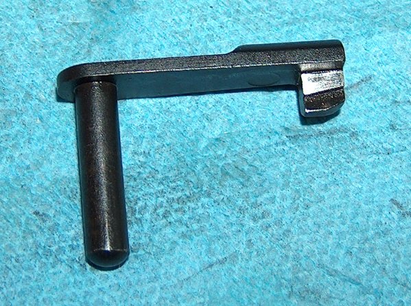
Not a stopping point.
Actually, I lied: There were two problems with the slide stop, but I didn't discover the second issue until the slide stop was able to fit in place: The top was too high to permit the slide to move. My files hadn't even grown cold, but I knew the drill: Fit, check. Fit, check. Fit, check. Repeat for about twenty minutes, or until the slide moves freely.
I topped my earlier fitting job.
In the process of filing down the top of the slidestop, I was able to make some observations. The top of the slide stop affects the way it functions, which is not too surprising, seeing as how it's the part that actually does the work of holding the slide open. Without a slight forward slope, the stop will catch the slide without a magazine in place. This is all fairly logical when you think about how the recesses in the slide move over the top of the stop, but my introduction to the concept came by way of trial and error. Business as usual, really.
The slide stop in action.
I cold-blued the exposed metal on the slide stop and was finally able to throw the gun together and test its complete function with snap caps. Hand- cycled ejection showed a tendency to eject horizontally, which indicated that the extracter tension might need adjustment. Hand-cycled rounds are not indicative of actual performance, though; I was just glad it extracted the snap caps at all.
Speaking of hand-cycling, working the slide by hand felt quite rough. I credited that to the bead-blasted mated surfaces working in. If more hand- cycling didn't fix things, there was always lapping compound.
In addition to the rough slide motion, the trigger was amazingly heavy and featured a definite two-stage creep. It functioned properly, so I decided not to worry about it for the time being.
I popped open a beer and relaxed. All of the above slide to frame fitting had been done over the course of a few hours, which translates to a fairly frenetic pace. (This is why this section doesn't feature many photos.) As fast as I had worked, though, it was now fairly late. Glamor photos of the assembled gun would have to wait until the following evening.
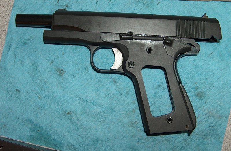
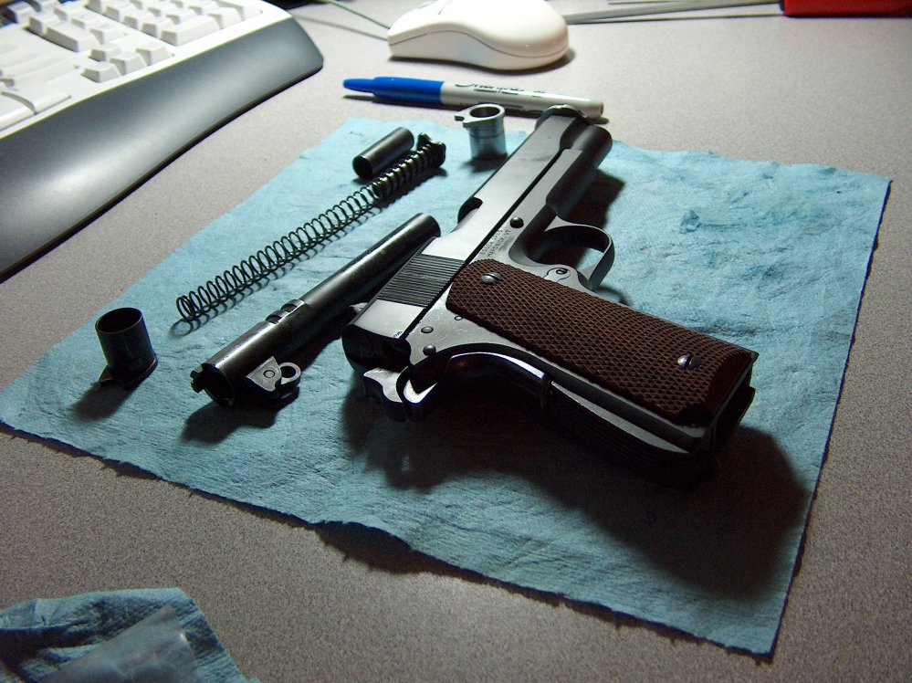
For the first time since starting this project, I was able to hold the fully- assembled gun in my greasy hands, as well as photograph it lying on a greasy shop towel. The general theme I'm trying to communicate here is one of grease.

Greaseful lines.
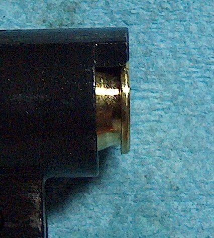
If you look closely at the above photo, you'll notice a faint gold-colored streak forward of the ejection port. This is what happens when you forget to remove your wedding band when field-stripping a 1911, and provides a great illustration of who wins when soft and hard metals meet. I'm just glad I don't wear a tungsten ring.
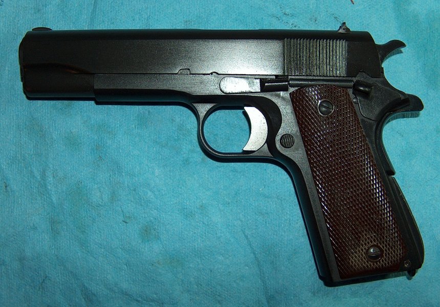
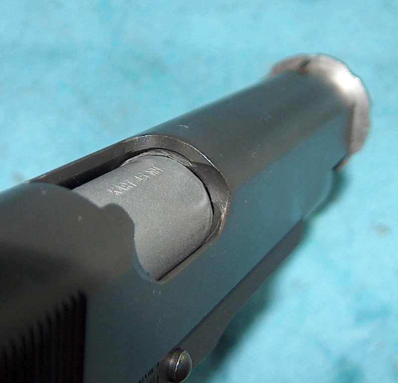
Looking at things from the other side.
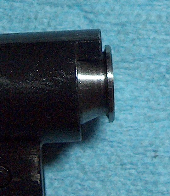
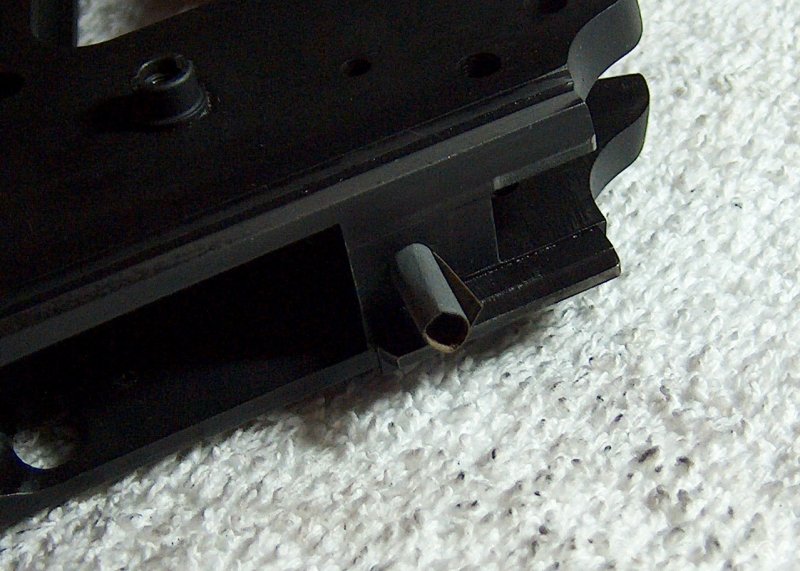
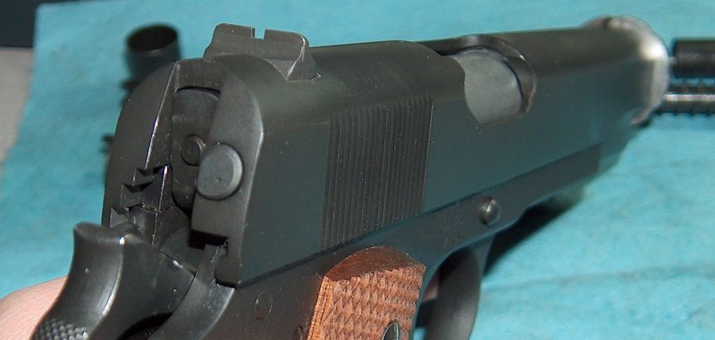
Sharp-eyed people may have already spotted it in the above photos, but it wasn't until I held the assembled pistol in my hands that I noticed the rear of the slide sat forward from the rear of the frame.
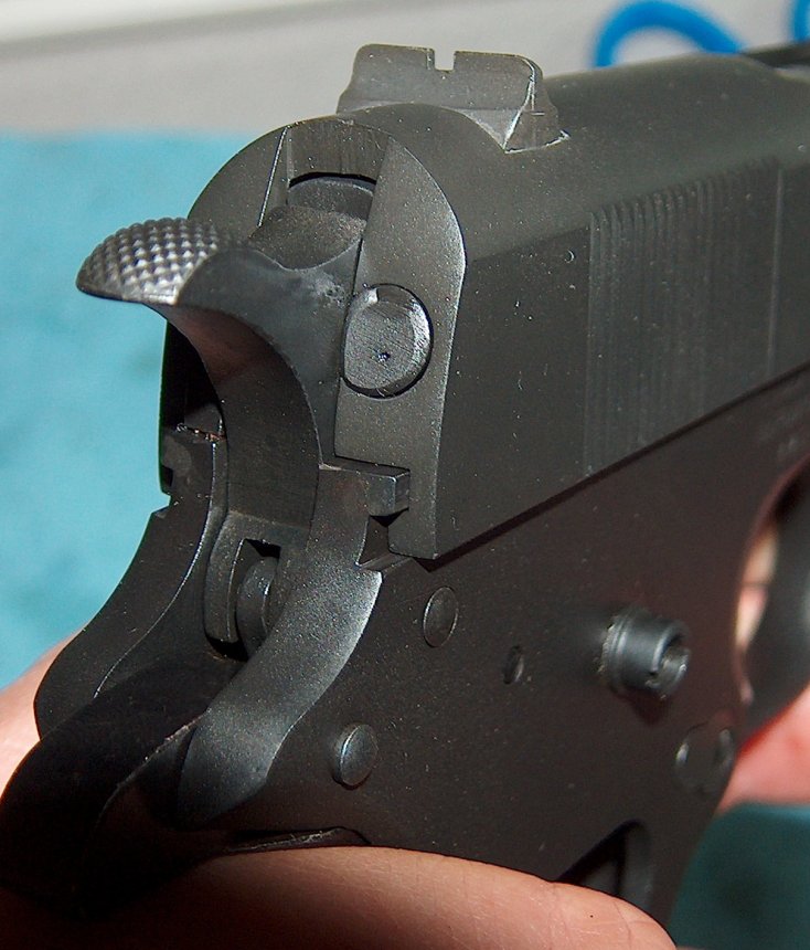
A forward-thinking slide?
Note the little dimple on the rear of the extractor in the above photo; somebody performed Rockwell hardness testing on the extractor. Of course, I don't know if it passed or failed.
Returning to the matter of the slide/frame mismatch, I'll spare you an account of my tortuous research into what causes this sort of thing and just provide the information. There are three areas that can contribute to a slide that sits forward on the frame:
Gosh, that sure narrows it down!
The slide is an obvious culprit; in the above photo it just looks like the rear of the slide doesn't come far enough back. Alternately, the lug recesses inside the slide, if located too far to the rear, make the barrel sit farther back relative to the front of the slide; this means the barrel's lower lug is also farther back, so the slide has to sit forward a bit in order to bring the barrel's lower lug into contact with the slide stop.
Of course, if the barrel's upper lugs are too far forward, you get the exact same result as if the slide's lugs are too far to the rear. There's also another gotcha related to the lower lug, especially if a drop-in barrel is used: If the barrel's lower lug is too large, the gun will not go into battery; therefore, drop-in barrels' lower lugs will err on the side of being undersized, and an undersized lower lug moves the entire slide forward until it rests on the slide stop. You could also get the same results if the lower lug is located too far toward the rear of the barrel.
All this talk of things having to move forward to the slide stop ignores the question of whether the slide stop is in the right place. As the slide stop hole moves forward relative to the rear of the frame, so does the slide. There's also the chance (unlikely in my case) that the rear of the frame could be built with a little bit of extra material to permit blending the slide and frame for a really snazzy-looking custom fit.
Finally, it's possible that every single one of the above flaws is present; in fact, each part could be in spec, but if all the measurements that contribute to the location of the slide on the frame fall toward one end of the acceptable range of measurements, the additive result of these discrepencies can be large. This is spec-stacking, the mechanical equivalent of a game of "telephone."
For this particular gun, evidence pointed to a combination of an undersized lower lug on a drop-in barrel and an out-of-spec slide, although I still wonder if the Essex frame is a built slightly long at the end to permit blending.
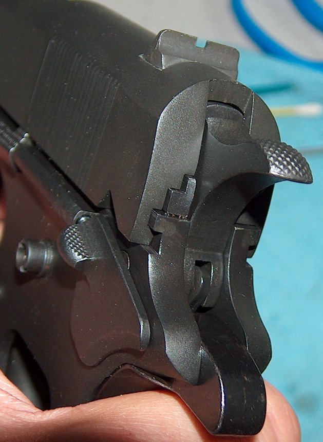
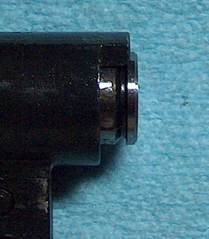
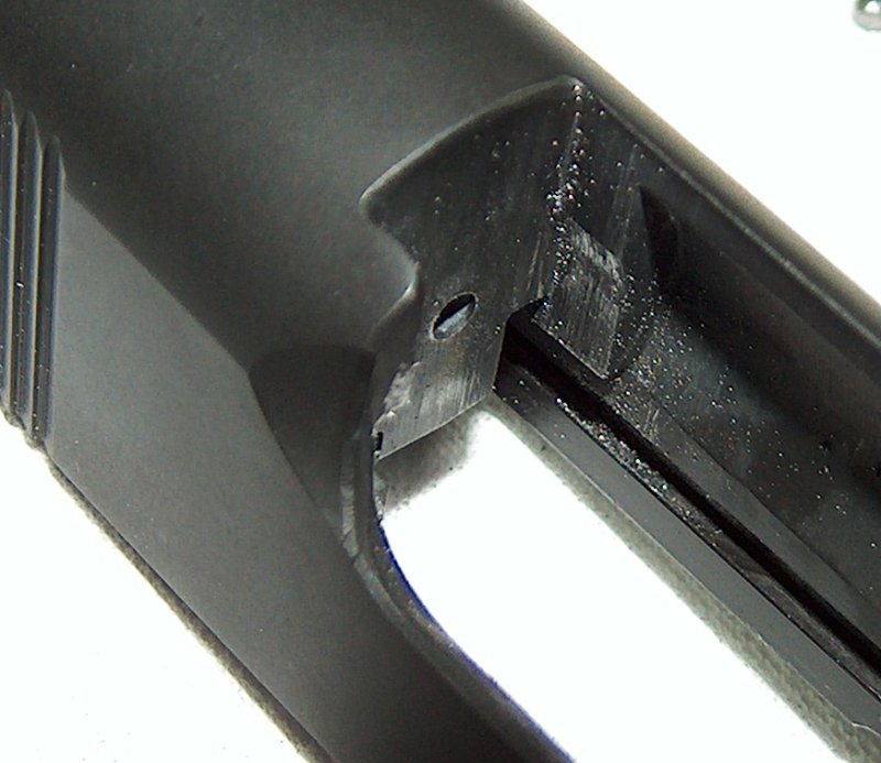
Note the rear of the ejector.
In the above photo, the rear of the ejector sits slightly forward of the rear of the frame; normally, these two should be flush. Although it's possible the ejector is too short, if the manual safety is engaged and the slide shoved back as far back as the safety allows (to correct for an undersized lower lug on the barrel), the slide only goes back far enough to sit flush with the rear of the ejector, not with the rear of the frame.
I would later learn that other people who used the slides sold by Sarco also experienced similar problems, and that these problems disappeared when different slides were used.
Headspace, for those unfamiliar with the term, is the maximum amount of longitudinal room permitted between the chamber shoulder and the breech face: the length of a hypothetical cartridge that fits perfectly between the chamber and the breech with its mouth at front of the chamber and its base pressed against the breech. Headspace that is too short won't close completely on a cartridge and the gun risks firing out of battery, which lets the cartridge back out of the chamber under pressure, exposing the weak area of the brass cartridge, which can then rupture under the pressure. Too much headspace is also a bad thing for pretty much the same reasons: The excess space lets the cartridge back out of the chamber to the point that the weaker brass walls of the cartridge are exposed. The only difference here is that this happens while the gun is in battery.
Measuring the upper and lower bounds of headspace is done with the use of go and no-go gauges, surprisingly expensive cylinders of metal shaped like bulletless cartridges. A gun with proper headspace should go into battery with a go gauge in the chamber, but fail to do so if a no-go gauge is substituted. A go gauge is 0.890" long, the minimum acceptable chamber length of an M1911, and a no-go gauge represents the maximum of 0.920". A gun should go into battery on a go gauge, but fail to do so with a no-go.
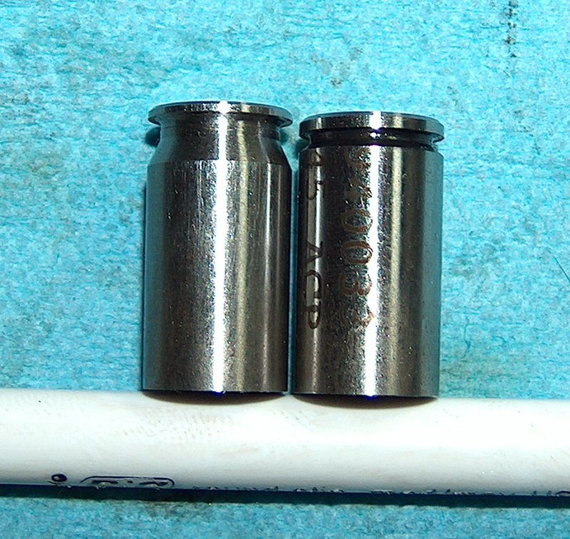
An engaugeing sight.
Above, you can see the difference between a no-go gauge on the left and a go gauge on the right. The actual difference in length is pretty minor when looked at side-by-side, and it's still minor even if you go by the numbers: Three hundredths of an inch is not a huge margin of error. It's as if the chamber is designed to contain tens of thousands of pounds of pressure or something.
But one thing the chamber is not designed to contain is a no-go gauge, so I removed the extractor, put the gauge in the chamber, and pushed the slide to.
Don't go there.
The slide didn't close on the no-go. So far, so good.
No closure.
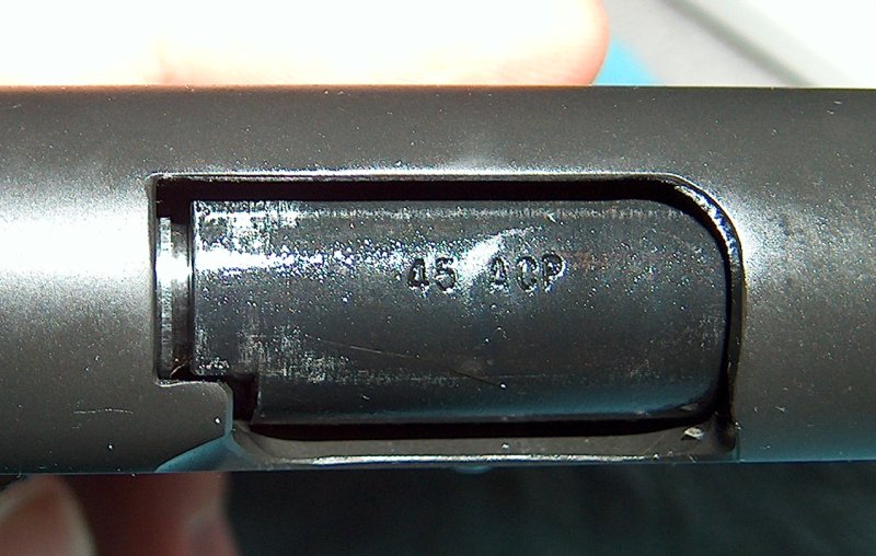
Unfortunately, it was the same situation with the go gauge. In the interests of seeing what was going on, I pulled out the barrel and inspected the gauges in the chambers to see how far they protruded.
No-go gauge
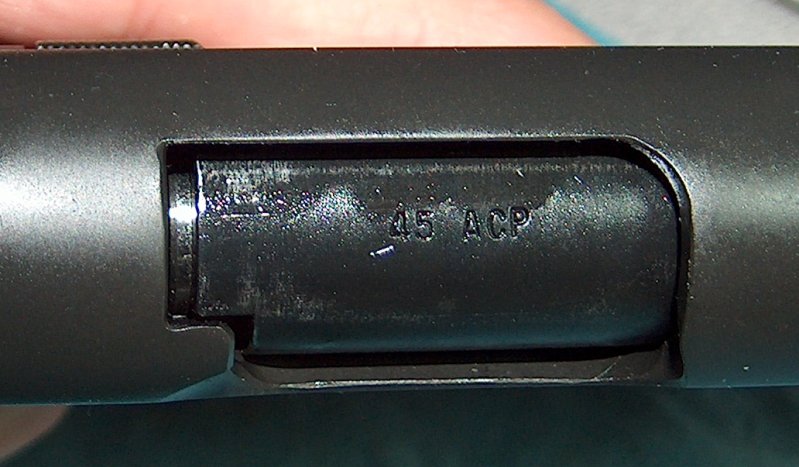
Go gauge.
The gauges protruded by a great deal. However, I ran across a clue while inserting them into the chamber for the above photographs: The gauges tended to take more effort to push as they went into the chamber, which meant the chamber was tapered. Furthermore, the chamber surface felt rough against the edges of the gauges. The barrel had an unfinished chamber, so it would need to be reamed out.
This put me in a difficult position: Getting a gunsmith to ream the chamber would cost almost as much as the barrel itself, which wasn't that great a barrel to start with. I decided to give up on this barrel and invest in another of higher quality, so I ordered an Auto-Ordnance barrel and link. (The previous sentence would turn out to be very ironic.)
Just for the shell of it.
In case you're wondering whether the gauges are really necessary, take a look at the photo above. On a whim, I grabbed a round of Winchester ball ammo and slid it into the chamber; it fitted perfectly because the case was crimped around the bullet, lending it a slight taper where the the gauges were perfect cylinders. Had I tried to fire the gun with this unaltered barrel, cases would have suffered sticky extraction or chambering issues at the very least.
With this barrel written off, I had Auto-Ordnance's charming four-to-six-week parts weight to endure until a replacement arrived. Fortunately, I had plenty to do...
While waiting for the new barrel, I decided to look at the wear patterns. There had been enough A-Zoom aluminum snap caps hand-cycled through the gun to show where parts were wearing on each other and I wanted to ensure that all of the wear was superficial and wouldn't progressively turn into peening.
First up was the slide stop and the corresponding notches in the slide. I wasn't worried about the slide stop itself, as a slidestop heat-treated to spec will be very hard, much harder than the slide itself. If anything is going to be damaged by an improperly shaped slide stop, it will be the slide.
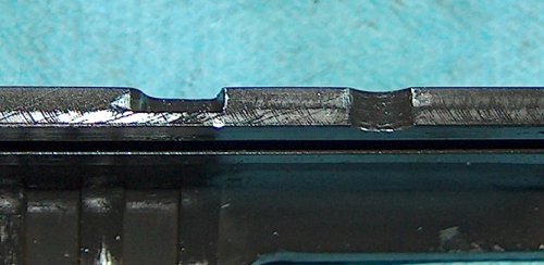
Stop wear.
At first glance, the slide in the above photos doesn't look too bad, but bear in mind that this photo was taken after a relatively small number of cycles. There's some peening starting around the edge of the disassembly notch, and the locking notch is showing a small amount of deformation near the front and rear. Nothing world-shattering, but worth some attention.
Let's take a look at the guilty party.
Wear did that come from?
The first thing I spotted when taking a look at the slidestop was that the top was wearing unevenly, which meant that when I filed it down to fit the slide I'd not kept the top completely level. Lesson learned: When attempting to evenly file a flat surface, use a solid backing for the file or stone.
As it happened, my filing of the surface was also the source of the peening. When the top of the slide lock was lowered, it also had the effect of removing the radius on the front and rear edges. (The change to the angle of the top also probably had something to do with it.)
To fix things up, I evened out the top of the slidelock and added tiny radii to the front and rear. The front radius was especially difficult given the hardness of the metal and the limited space in which to work.
Was I done with the slidestop? Not quite:
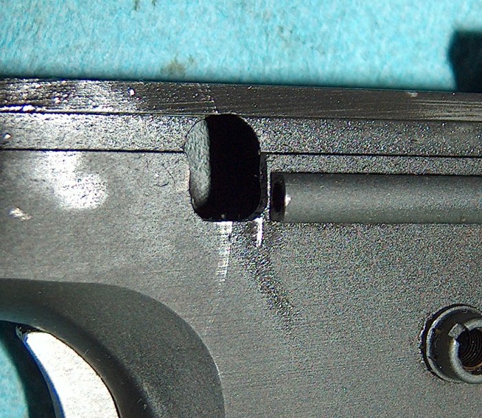
A pair of idiot marks?
The "standard" idiot mark is my fault; I defy anyone to assemble and disassemble a 1911 twenty times in an hour and not ding anything. However, the small gouge right before the plunger tube can't be laid at my feet. This was caused by the rear corner of the slidestop biting into the frame itself. To fix it, I relieved the stop a bit so that it cleared the frame, then rounded the rear corner just a little, so that even if the stop contacted the frame again it wouldn't dig in.
I was done with the slide stop, so I cold-blued it and turned my attention to a couple other worrisome points.
Ring around the rosies?
I'd noticed a faint ring near the front of the slide and was worried that the bushing might be shifting and deforming the interior of the slide.
No beating around the bushing.
As it turned out, I was being silly because the bushing didn't even match up with the mark, which is probably a machining mark.
Finally, I noticed what appeared to be serious wear around the right front corner of the frame rail where it met the dust cover. This worried me a great deal because corners are highly susceptible to cracking; if something was bearing hard against that corner, it wouldn't bode well for the frame's long- term durability. However, the wear just didn't seem logical to me for some reason, so I looked closer. There was no corresponding heavy wear on the slide where it met that point in the frame at full rear retraction, nor was there corresponding wear on the other side. I had to haul out the magnifying glass before I realized what had happened: The A-Zoom aluminum snap caps had gotten lightly chewed up by all the cycling. A flake of aluminum had come off and somehow migrated forward. (Not surprising; if you've cleaned a 1911, you know there's nowhere fouling can't go.) The aluminum had been pounded into the corner by the slide cycling, so much so that it looked like raw steel and took a pick to remove. This was a somewhat silly false alarm, but the fact that the "wear" had instinctively felt wrong to me was heartening. Maybe I was learning something after all.
With the major areas of wear (weareas?) addressed, I still had to wait another two weeks before the Auto-Ordnance barrel arrived. You, however, need only click the link below.
At long last my Auto-Ordnance barrel, link, and link pin arrived. My patience was richly rewarded with an utter piece of crap. Out of the bag, the barrel had rust on the hood and minor pitting in the bore, neither of which were beyond minor cleanup, but any one of which would have been sufficient to make me uneasy about Auto Ordnance's quality control. That, and the fact that the link they sent was warped to the point that it wouldn't rotate when inserted between the lower lugs. The link pin was okay, though; apparently a small cylinder of metal is within Auto-Ordnance's manufacturing abilities.
I decided to make lemonade by cleaning up the rust and transferring the link and pin from my other barrel. In retrospect, it would have been quicker and less painful to have just sent everything back and demanded a refund. Then again, it might not have turned out that well; any company that will sell someone such clearly malformed parts isn't one I'd bet on for good customer service.

Hood left, post rust-cleanup.
The rust on the hood cleaned up with some sandpaper. I'd been planning on sanding the hood anyway, since the top was polished white, but only in the area that would show through a standard ejection port. My slide had a lowered ejection port, so I needed to extend the polish down to keep it from looking weird. The bore cleaned most of the way up with some bore paste and elbow grease.
Hood right; note larger area of shininess.
I put together an impromptu bench block using a scrap of 2x4, a hammer, a chisel, and a drill. This made it possible to drive out the link pin from the old barrel for use in the new one. (I discovered that press-fitting a link pin to the lugs never really gets any less hair-raising.) With the barrel thus assembled, I eagerly grabbed a go-gauge and dropped it into the chamber, where it completely failed to fit. Closer inspection of the chamber showed that it was even worse than the other barrel: heavily tapered and full of machining marks.
It looked like there was no escaping the need to have the chamber finish- reamed, so I found a local gunsmith and paid him $40 to do so. When I picked up my barrel, he pointed out that the chamber was formed incorrectly, leaving a shallow void on the left side. Although not dangerous, a chamber void near the front will cause cases to expand unevenly in the mouth area, possibly retarding rearward slide motion when dirty or old, soft cases are used. Later, I would realize that he'd also tried to do me a favor by grinding down the edge between the chamber and barrel ramp, but only succeeded in destroying the barrel's feed reliability.
Avoid.
Grimly determined to follow this particular comedy of errors through to the last scene, I gathered the materials necessary to measure vertical lug engagement.
Precision gunsmithing equipment.
Although perhaps less necessary when fitting a barrel where one can control the exact amount of vertical engagement, it's usually a good idea to measure vertical lug engagement, especially for drop-in barrels. The lugs are responsible for holding nearly eight tons of pressure; if there's not a large enough area of metal available to hold the pressure, it'll exceed the tensile strength of steel and peening will occur. As the lugs peen, the headspace opens up. Once headspace gets large enough, enough of the case above the web will be exposed to permit bulging and eventual ruptures.
Browning's original design called for all three lugs to be engaged, with the first lug seeing almost complete engagement. (Due to the angle of the barrel necessary to clear the slide during recoil, equal engagement of all three lugs is not possible.) Through the WWII era, barrels were fitted as closely as possible by hand, then a proof round was used to pressure seat all three lugs. Modern hard steels don't permit this method of engagement, and most factory 1911s use drop-in barrels to keep prices down. As a result, almost all stock 1911s use only a single partially-engaged lug to hold the barrel in place. It's a testament to the strength of the design and the power of metallurgical advances that the gun is even capable of repeated use under these circumstances, but consider the possibilities: If you can get good engagement for all three lugs, the rifling will wear away before the gun shoots loose.
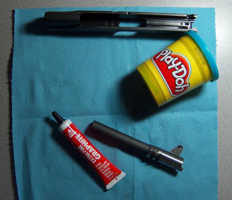
But I digress. This barrel sure as heck wasn't going to get full engagement on all three lugs, so I wanted to see what I had to work with. Step one involved filling the space between the lugs with Play-Doh, no modelling clay being available. Also, Play-Doh smells nice.
Just like Kindergarten, except I was only shooting 9mm then.
In order to prevent the Play-Doh from sticking to everything, I coated the lugs with graphite. It didn't help, but at least I got graphite all over the place.
25% less sticky, 200% more messy
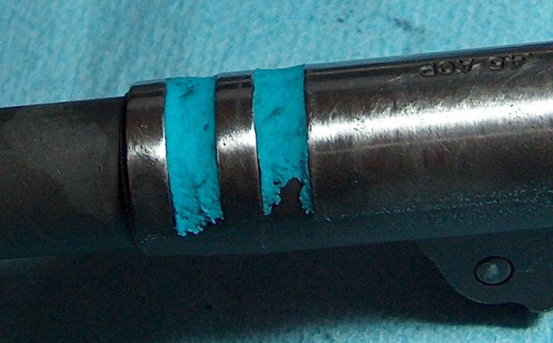
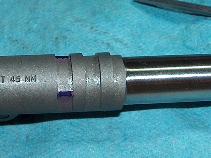
Fitting the barrel and bushing to the gun, I pressed the barrel into place, then carefully lifted it clear. As the photo below illustrates, one should use as little material as possible, since excess will be forced out and then catch on the upper lugs as the barrel is retracted, ripping out most of your hard work. The photo also shows the deeper engagement of the first lug.
The face of scientific measurement.
Using the depth measuring part of my micrometers, I was able to get a very rough estimate of how far below the lugs the Play-Doh had been compressed. The first lug was getting 0.038" engagement, and the second had about 0.035". Not great, but close enough for government work.
A more important measurement was the amount of headspace available. To determine that, I pulled the extractor, then placed the barrel in the slide along with the bushing and inserted a go-gauge. Pushing the barrel as far forward as it would go, I inserted feeler gauges between the barrel and breech face until I found the one that just barely fit: 0.010". Since the go-gauge is 0.898" long, that meant that the total headspace was 0.908". The allowable maximum is 0.920", so the barrel was a little on the high side where headspace was concerned, but nothing to worry about provided the case web had proper support.
Following the measurements, it was the work of mere hours to get all the Play-Doh out of the slide and barrel lugs. With the lugs measured and the gun cleaned, it was time to fire it for the first time.
The day dawned overcast, damp, and slightly chilly: standard fare for Washington state. I was not deterred by the weather, though, for today I would be firing my 1911 for the first time. Bolting my breakfast, I hurried to the range with the newly-completed gun. With the targets in place, I chose a magazine, loaded a single round, and with nervous hands tripped the slide release.
Clunk.
Anticlimax.
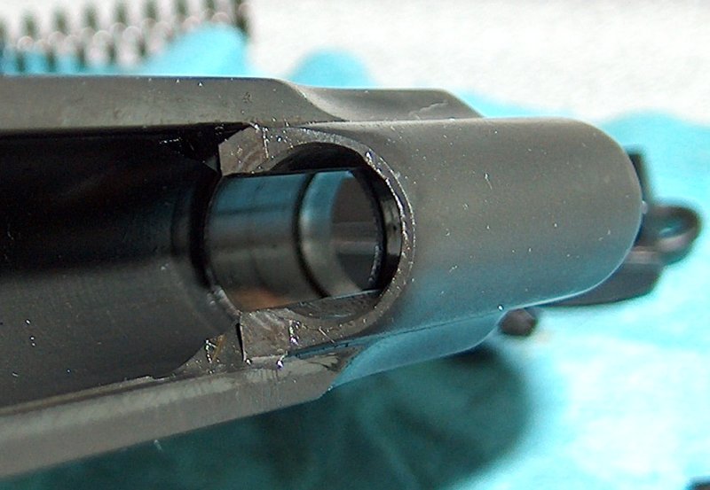
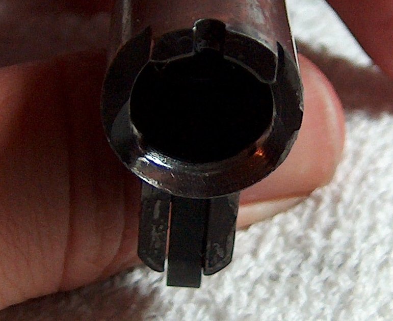
The round didn't even feed off the magazine, no matter what I tried. This was definitely puzzling, as snap cap after snap cap had fed through this very same pistol. Disappointed, I returned home to investigate further. The complete and utter failure to feed under all circumstances made it highly unlikely that this was a standard jam; more likely was the possibility that the cartridge was being prevented from sliding up the breech face. The extractor was the likely culprit here, but it didn't look like the rim was even making it high enough to engage the extractor:
So what extractly is the problem?
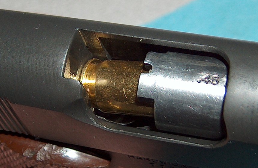
Finally, I measured the breech face width at the bottom and found it was 0.475" across, which wouldn't be a problem if .45 ACP didn't have a rim width of 0.480". I'd heard of this problem occurring in slides found on Sistema Colts, but had never expected to run into it myself. The snap caps had worked fine because they were built undersized to start, and the edges of the rims had been chewed up by repeated chambering. I'd found bits of aluminum inside the gun, but it had never occurred to me to wonder which part of the snap cap had produced those chips.
Widthout a doubt the source of the problem.
The solution is to open up the bottom of the breech face to about 0.484" wide by taking material evenly off both sides, beveling the extractor's tensioning wall to make the bottom flush with the new width if necessary. More room can be provided by taking an addition 0.004" off the side opposite the extractor, bringing it to 0.488". Some builders will open it up all the way to 0.490", but removing the minimal amount of metal is always a good starting point. A slight bevel on the bottom edges of the breech face will help funnel the rounds into place and complete the job.
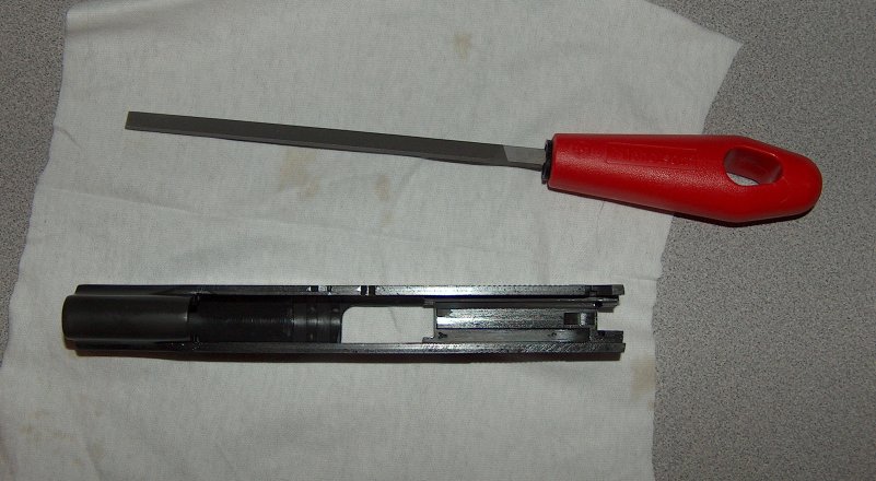
Rank and file.
The tool for this job is a narrow #2 Swiss cut pillar file. Swiss cut files are cut with fineness proportional to their number, so #2 is fairly fine. Someone who knew what he was doing and had several of these things might opt to start with a #0 to open up the face to within a thousandth of an inch of where he's trying to go, then sneak up on the final measurement with a #1 or #2. As a ham-fisted amateur, I opted to take it nice and slow.
Defiling the slide.
After opening up the extractor side of the breech, I proceeded to the opposite side. In both cases, the filing was tricky work due to the limited space and constricted angles; maybe a #0 file would have helped speed things up.
Opening up the breech under the extractor left a little bit of the extractor exposed, so I very carefully used a small needle file to add a bevel to it, then cleaned it up with some 600-grit sandpaper.
The bevel's in the details.
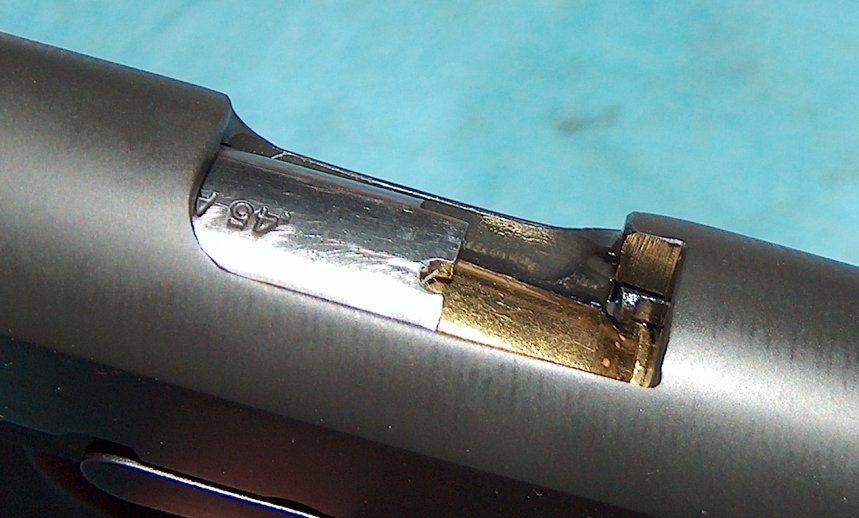
With the extractor beveled, it fitted nicely with the reshaped breech face:
We've breeched a stopping point.
I'd thought filing the breech face open had been a chore, but it was nothing compared to putting a bevel on the bottom corners. I finally managed to put a small bevel in place, but it was very difficult to do while avoiding inadvertently filing other parts of the slide.
One final thing to note is that after extensive filing in one place with a single file, you're left with some fairly deep filing ridges. Standard metalworking procedure, I'm told, is to file with successively finer and finer files until the ridges are reduced; I had to use sandpaper wrapped around the file. It worked, but I could see how the proper tools would have made the job a lot easier. What a strange concept.
After cleaning up the filings and reoiling the gun, I was ready to go again. Now I would definitely be able to test-fire the gun for sure. Not like last time.
Or would I?
After the previous week's anticlimax, I didn't know what to expect from the second test-firing attempt. Feeding tests with dummy reloads showed that the feeding issue had been fixed by widening the breech face, but what other unanticipated snafus lurked beneath the gun's innocently parkerized exterior?
There was only one way to find out.
This time, the gun chambered perfectly and fired well, ejecting its single case just like a good semi-auto should. The hole it put into the target was also reasonably close to the point of aim, although any discrepencies there could be laid at my feet, as I was nervous at first. The ejected casing showed no deformation, though, and inaccuracy due to nerves slowly gave way to inaccuracy due to excitement.
Transitioning to two rounds showed no doubling. As horribly heavy and creepy as the trigger was, the firing mechanism was at least safe. I switched to full magazines and continued to test-fire, looking for hammer-follow, doubling, bulged cases, or any other safety hazard, none of which surfaced. However, cases turned out a bit lopsided near the mouth due to the void in the chamber.
As I was testing for safety, I noticed a minor ejection problem. Although most rounds were being extracted to a point roughly four feet behind me and two to the right, the occasional shell would get thrown forward or straight to the side. It wasn't stovepiping, but it was still irritating and left brass flecks on the front corner of the ejection port. Either my extractor hook was too deep or my slide wasn't coming back with enough force to let the ejector do its thing. Given that the slide had never been lapped to the frame, I was betting on the latter.
I also had one failure to feed with ball ammo, a three-point jam that occurred roughly halfway through my 100 testing rounds and didn't reappear. It may have been a break-in fluke, but I made note of it and resolved to keep my eyes open for any clue as to what caused the problem when performing the post- test examination of the gun.
As I mentioned above, the gun's accuracy suffered from being shot by yours truly via its horrible trigger, but otherwise appeared pretty good. Speaking of triggers, I came to realize that the long target trigger in the gun had some sharp edges that were not at all finger-friendly. All the more reason to switch to my preferred A1-length trigger.
Still, this was a good trip. I had expected to have some things to touch up, but I didn't expect the gun to perform quite as well as it did: Fresh from the bench, it had provided 100 mostly error-free rounds. (I didn't consider the forward extraction an error as it didn't tie up the gun.) Still, there was some work to be done.
I started with the extractor. Just back of the hook, its width measured between 0.078" and 0.079". The width at the hook came in at 0.112", which put the hook depth, the difference of these two numbers, at between 0.033" and 0.034". Given that an in-spec extractor hook is between 0.032" and 0.036", my extractor was probably not the source of the ejection misbehavior.
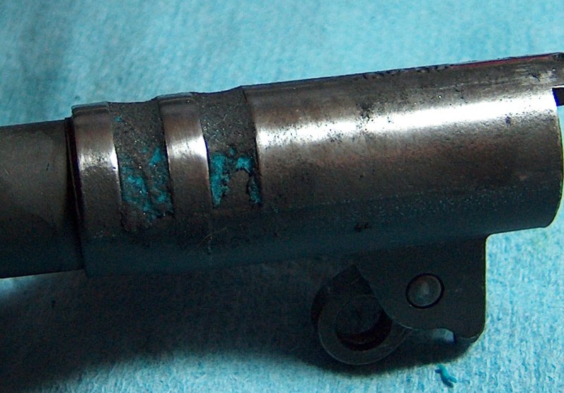
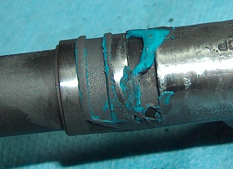
However, I did have a likely culprit for both the extraction issues and the single three-point jam: the same breech face clearance issues that had caused failures to feed the previous week. Hand-cycling the gun showed some reluctance to link down that was attributable to the rim of the round squeezing against the sides of the breech. My clue came from noticing gouges on the barrel hood: Something was stopping it from linking down before the slide came back and hit it. I cleaned up the barrel hood gouges and then opened up the breech face a bit more on the side opposite the extractor to ensure the gouges would not return. I also noticed that the gouges were more prominent on the hood opposite the ejection port; this indicated that either the barrel's lower lugs or the slide's lug recesses were uneven, or both at once. Quick examination showed slight asymmetry in the slide's lugs, which had a slight protrusion that matched up perfectly with the marks on the barrel hood. I carefully relieved the protrusion, then polished the lug area of the slide.
The last check I performed involved the barrel's headspace. It was likely the lugs had seated slightly, so I wanted to ensure that headspace hadn't opened up to a dangerous degree. A 0.89" case admitted a 0.019" feeler between it and the breech face when the barrel was held forward in the slide, indicating a combined headspace of 0.909", which was 0.002" longer than the initial measurement, but still below the maximum of 0.920".
Having checked post-seating headspace and addressed what I believed was the most likely cause of extraction and feeding issues, it was time for another trip to the range.
I returned to the range with the mildly-tweaked 1911 to see if my work had effected a noticeable change. I'll spare you any suspense and just say that no, it didn't make any difference. Failures to feed and forward extraction were still in evidence.
However, the way that something fails often provides more information about how it works than proper operation reveals. In this case, I was able to confirm that forward ejection came about due to retarded slide movement to the rear. Assisting in this diagnosis was a box of 200-grain lead semi-wadcutter cartridges over a light load of gunpowder. These would impart less momentum to the slide when fired, so if the slide was hanging up during recoil, they should eject to the front more than full-power 230-grain ball ammo. My hypothesis was confirmed, as almost every single wadcutter round ejected to the front, while the ball ammo was more hit-or-miss. Something was still grabbing the slide on its way back.
Additionally, this second round of testing revealed even more failures to feed. Widening the breech face hadn't fixed those issues, so it was clearly something else entirely. I turned to the M1911.org forums to ask what could be causing the feeding issues. One of the photos I attached to this question was the image of the barrel ramp below.
What could possibly go wrong?
I posted the above photograph in the gunsmithing section of the forums, and within moments 1911 experts around the world spat coffee onto their keyboards, which they then used to type invective-laden posts, the gist of which inevitably boiled down to, "what the #$@*& did you do to your barrel ramp?"
It seems that the "gunsmith" I hired to ream the barrel's chamber decided to do me a "favor" and hogged out the barrel ramp at the same time in the interests of making feeding more reliable. Unfortunately, it doesn't quite work that way, as his efforts only created a sharp edge that caught the ogive of the bullet during feeding and compromised case web support for anything that actually managed to make it into the chamber.
1911Tuner generously offered to fix up the barrel if I wanted to ship it to him, but I declined on the grounds that it would be throwing good effort after bad. This barrel wasn't that great to start with and had a void near the front of the chamber already, so throwing more time into it, especially someone else's time, would be a waste. Better to just spend the money on a high- quality barrel and fit it to the gun, like I should have done from the start. By this point I had well over $100 dumped into cheap barrels, none of which worked. It's true what they say: Buy cheap, buy twice.
The barrel was a dismal failure, but maybe I could achieve some success with the extraction issue by removing any impedence to the slide's rearward motion. Lapping the slide to the frame was an obvious choice, but unlike most obvious fixes is the right thing to do. The motion of the slide against the frame had smoothed out some with the first shooting session, but some lapping made it downright silky.
Not content to rest on my laurels (they get wrinkled when I rest on 'em), I looked for other areas of possible rearward friction. Another obvious one was the disconnector. The disconnector that came with my parts kit was a little on the long side, but that's better than being too short. However, to eliminiate the possibility of slowing the slide down, I knocked down the high spots and did some very tentative polishing of its face, being careful to remove no metal from its tip.
Disconnector front.
Disconnector rear.
Notice that I didn't remove any metal, but just knocked down the high spots that might be causing friction. I did the same for the disconnector tunnel, exercising caution that the tunnel opening was not enlarged.
Change the channel.
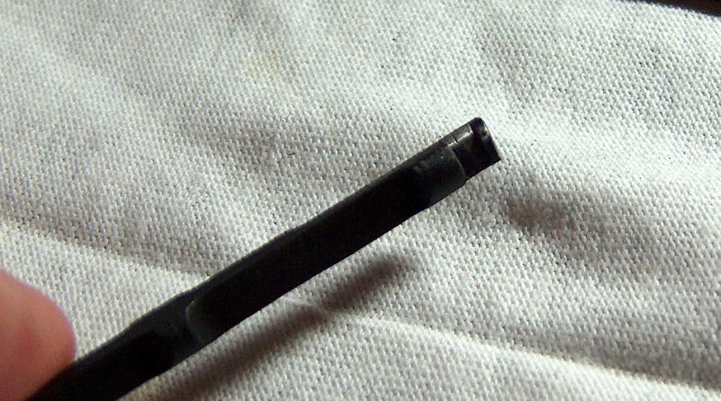
Since I was tweaking things, I decided to fix the hammer strut pin, which had a bad habit of walking out. It hadn't bound up the action yet, but a new hammer strut pin costs a dollar at most and removes any chance of this occurrance. Given the amount of force required to tap it into position, the possibility of it walking out is laughable.
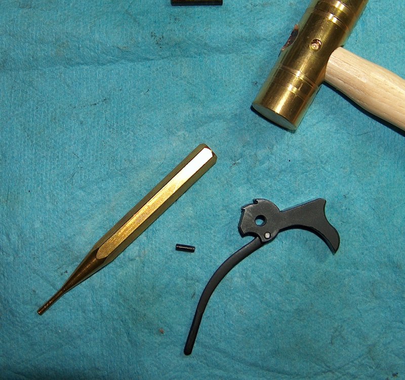
New hammer strut pin after gentle insertion.
Then there was the issue of grips. Thus far, I'd been using the plastic USGI surplus grips that came with the parts kit. Those worked well enough, but I wanted real wood grips, preferably walnut. These were intended more for feel than looks, as the appearance of this 1911 I was building was almost certain to win few beauty contests. Wood grips feel warmer than plastic and tend to absorb sweat instead of becoming slippery. All that being said, wood grips look awfully nice to me no matter what kind of gun they're on. I was able to find some inexpensive wood grips online featuring GI A1-style checkering. One of the nice things about the 1911 is that its grips require little inletting and are simple to make, so wood grips don't cost an arm and a leg like they do for some handguns, such as S&W revolvers and Browning Hi-Powers.
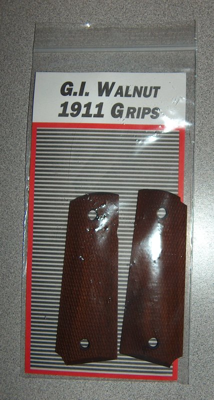
The only cheap parts that worked perfectly.
Finally, I scored a victory for both aesthetics and ergonomics with the purchase of a short, ridged trigger at a gunshow. Although I fished the part out of a bargain bin and paid a scant $3 for it, it fit and functioned pefectly.
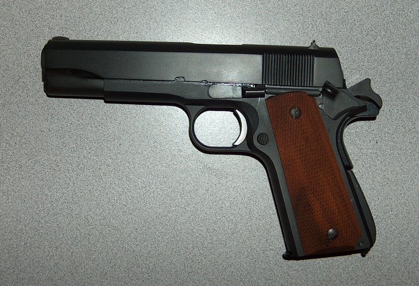
New look and feel.
These minor upgrades provided minor improvements in ergonomics, but the big issue was still the feeding problems caused by bad work on a bad barrel. Given that I intended to take a brief hiatus from all things barrel-related until my aggravation returned to manageable levels, what did that leave for me to do?
As it turned out, plenty.
My earlier misadventures with 1911 barrels had unpleasantly and pointedly demonstrated the value of good parts. I was therefore determined to leave all lesser-quality components behind and settle for nothing less than a top-shelf hand-fitted barrel. Bar-Sto was a bit dear for my taste, and would have been out of place given the generally mediocre quality of the rest of the gun. Additionally, I didn't want to tackle a hard-fit barrel at this point, seeing as this entire gun project had me in over my head; when you dive into the deep end to learn how to swim, it behooves one not to do so while holding onto a cinderblock. Thus, I decided to go with a Kart EZ-Fit barrel.
Going from a cheap Roto drop-in to a Kart hand-fit barrel is like going from hot dogs to sashimi: It's a massive jump in quality, but the unrefined palate will find the more sophisticated of the two strange and a bit frightening. However, I took faith in the fact that the barrel was, per its name, "EZ" to fit. How hard could it be?
We will now pause while those who have fitted 1911 barrels laugh until they drool on themselves.
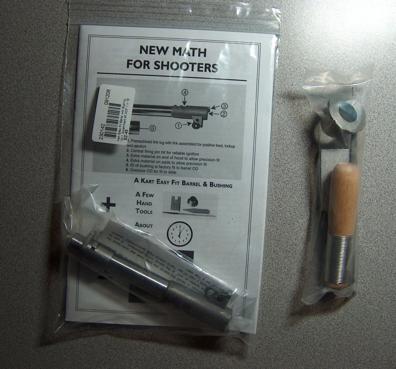
A new barrel is in the bag.
Above may be seen a brand-new Kart EZ-Fit barrel and barrel fitting kit as they appeared shortly after being unwrapped under the Christmas tree. (I have the best wife in the world.) Sharp-eyed observers will note that the enclosed pamphlet claims it is possible to fit this barrel in about an hour. I'll concede that for someone who knows what he is doing, fitting a Kart EZ-Fit may be the work of an hour, but those who are tentative, inexperienced, and/or uncoordinated (hi!), the entire process is far more involved.
Dramatic barrel fitting photo.
So it was with equal parts undeserved optimism and entirely appropriate trepidation that I gathered all the parts for barrel fitting one evening and got to work.
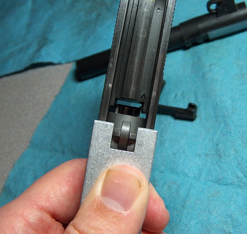
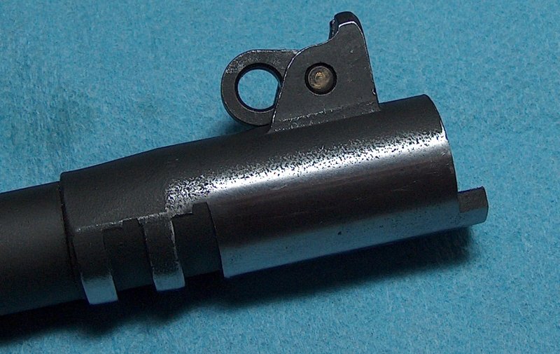
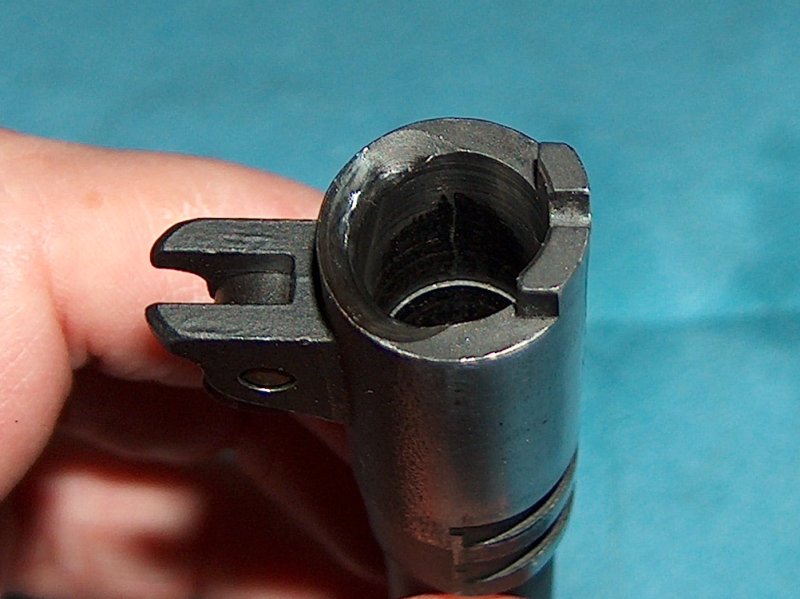
This must be why they call it an oversized hood.
The first step in fitting an EZ-Fit is to get it to go into battery. Our primary obstacle here is the fact that the hood is too large to fit into the appropriate recess in the slide, all the better to ensure solid lockup with minimal endshake. Both sides of the hood must avoid touching the sides of the recess when going into battery, otherwise the barrel will be forced onto the lower lug on the opposite side of the barrel from where the hood makes contact. This had never occurred to me before fitting a barrel, but there's a somewhat counterintuitive relationship between the barrel hood and the lower lugs: What happens on one side of the hood happens on the opposite side to the lugs. If one side of the hood jams against the slide, the lower lug on the opposite side will not be able to rise up evenly with the other lower lug and will jam against the slidestop pin. Conversely, if for some reason the barrel doesn't rise into battery in a symmetrical fashion, the barrel hood will reveal this by listing to one side or the other. (This last point wasn't apparent to me until I started filing the upper lug recess pads.)
After filing down the sides of the hoods, the rear of the hood was still too long to permit the barrel to go into battery, so that had to be filed down just enough to let the barrel drop into lug engagement. During the process of hood shortening, I ran into additional binding on the side, which I corrected. At first I was worried that I'd removed too much material from the sides of the hood until it occurred to me to compare it with one of the drop-in barrels: The hood width was actually a bit wider than the drop-in, which was a relief. This wouldn't be the first time I ran into issues due to being paranoid about removing too much material.
The fitted hood.
On a completely non-gun-related note, as I was filing on the barrel into the night I kept catching myself humming, "Let it Snow" under my breath. I packed up the parts and tools, turned around, and saw through the glass door that the backyard had somehow picked up three inches of snowfall. Spooky. I also saw that it was late at night, so I left the lug fitting for the next day.
After a fun day of driving over icy hills better suited for bobsleds than sedans, what could be more relaxing than some soothing barrel fitting?
Relaxation equipment?
Brain surgery, for one; or maybe some light demolition. Nonetheless, I was determined to continue work on the Kart. Getting the upper lugs to full engagement was next, inasmuch as I'd filed the barrel hood back enough to permit tentative lug engagement.
Or had I? The first time I tried to close the slide on the new barrel, it showed no upper lug contact at all, indicating a failure to go into battery. The hood was binding against the breech face while cycling; I still hadn't removed enough material. A few minutes of filing later, the upper lug pads started to show contact.
Like a dead flashlight, it's out of battery.
Verifying upper lug engagement is done by assembling the gun with the barrel to be fitted and filing down the pads on the upper lugs until the gun will go into battery, all while ensuring the the lower lugs make even contact with the slide stop pin. The funky bushing used during this process is a bench bushing, designed to be easy to insert and remove because you'll be disassembling and reassembling the gun about 6,000 times.
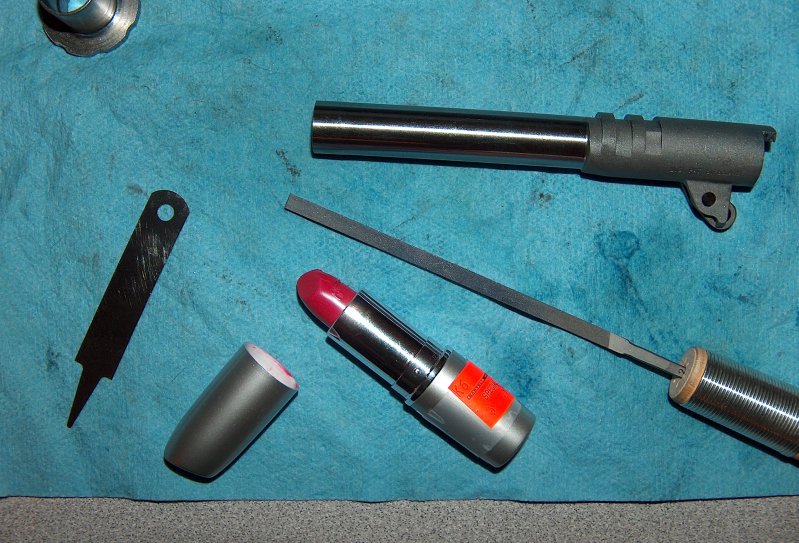
Precision barrel fitting equipment.
I should also probably explain how I'm detecting lug pad contact. Real metalworkers would have used contact marking fluid, but for the amateur on a budget lipstick from the Pay-Less discount cosmetics bin is easier to find, cheaper in cost, and far more humiliating to purchase. In fact, lipstick has one small advantage over contact fluid, in that it can be built up slightly so that near-contact is visible. It also cleans up relatively easily and makes your lips look full and luscious.
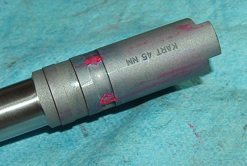
First contact.
Using the lipstick on the upper lugs showed which pad was seeing more contact, thereby indicating which one needed to be filed in order to bring the barrel up more. Additional clues used while raising the barrel included watching how the hood moved into battery; if the lug pads were unevenly filed, the barrel hood would lean to one side as the barrel rotated and lifted up on one of the lower lugs.
Speaking of lower lugs, those also saw some lipstick. What I was looking for here was even, symmetrical contact marks from the slide stop. Just like the sides of the barrel hood and the opposite lower lugs are related by their axial influence on each other, vertical lug engagement, front/back contact between the lower lugs and the slide stop, and in-battery position of hte slide are all related by the curve of the lower lugs. As the 1911 goes into battery, the barrel rides up the slide stop on its lower lugs. Because the Kart barrel has the raised pads in the first lug recess, the pads make hard slide lug contact before the barrel has lifted enough to let the slide stop pin clear the curve of the lower lugs, preventing it from going into battery and leaving a distinctive mark on the lower lugs:
Lug line.
As the pads are filed down, the barrel can rise higher, and the slide stop pin can move farther back. The goal is to let the barrel raise just high enough to let the slide stop pin contact the rearmost part of the lower lugs' feet. This creates an interference fit that locks the barrel into position in three dimensions. Vertically, the barrel is held between the pads on top and the lower lugs on the bottom. Front-to-back, it's held in battery by the recoil spring pressing the lower lugs forward against the slide stop and the barrel hood just barely touching the breech face. Horizontal engagement is maintained by the sides of the hood, the pads on top, and even slide stop pin contact with both legs of the lower lug.
Note that all of these contact points assume that the bushing is holding the barrel tightly and that the barrel is being fitted for maximum accuracy. As the contact points open up and the bushing gets looser, slop becomes possible and the amount of consistency in lockup decreases.
Enough theory! More filing!
To ensure I was filing the lugs evenly, I painted them with a Sharpie to reveal any unevenness. This didn't prevent me from making a fairly sloppy job of things, but at least showed me that I was doing so.
Marked for filing.
As I filed down the pads, the barrel rose and the gun went farther into battery. It was really neat to watch the hood's progress up the first slide lug, although it didn't move quickly enough to be dramatic.
Rising to the occasion.
Part of the reason for the slow progress was the tentative way I proceeded. This was exacerbated by the laborious procedure: Coat the pads and lower lugs with lipstick, assemble gun, push firmly as far into battery as possible. Disassemble, note any uneven contact points, remove lipstick from pads, apply marker, let dry, file, and repeat ad nauseum.
At long last, the lower lugs showed contact on the front of the feet and the barrel's vertical engagement was quite impressive. Still, the slide was slightly sticky going into battery, indicating that the lower lugs were binding on the slide stop pin. This confounded me for a while, but turned out to be another case of not removing enough material. (Still, it's better than the opposite extreme.) The fix here was to remove a fractional amount of material from the upper pads and lap the lower lugs to the slide stop pin with a slurry made of bore paste and oil.
In a slurry to get things fitted.
Even after doing this, though, some stickiness still persisted. I was wracking my brain in consternation until I noticed that the bluing in the upper section of the breech face was worn off: The barrel hood was still too long and was binding against the breech face. For the third time, I removed a little more material, fixing the stickiness for good and produced one smooth- cyling barrel. It just goes to show the degree to which symptoms may be caused by parts that seem completely unrelated to the problem.
I'm going slightly out of order here, because final fitting required the match bushing included with the barrel; however, the bushing also required fitting to the slide due to its enlarged outside diameter. FYI, trying to remove a stuck bushing from a slide is an awesome way to rip off any extra fingernails you don't need anymore. When fitting a bushing, always do so with the barrel inserted so that if the bushing gets stuck you can use the barrel to pull it out.
Turning down the outside diameter of a bushing by hand is indiscribably tedious and impossible to do evenly. After several hours of futile work, I yearned for a lathe. If only I had some tool capable of inducing rotary motion! Truly, this problem would be more easily solved if I had some sort of...rotary tool.
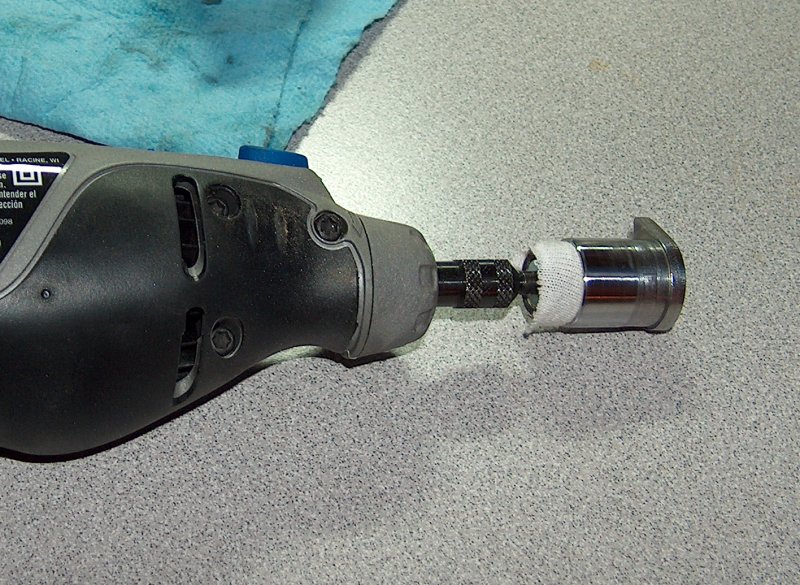
Precision gunsmithing strikes again.
Ironically, a Dremel acted as the solution to a 1911 problem instead of being the cause, as is usually the case. I used my Dremel's sanding drum wrapped in a scrap of cloth. The bushing, if carefully wedged onto the tool, rotated with almost no eccentricity, permitting the use of small files and strips of sandpaper and speeding up the reduction of its outside diameter by several orders of magnitude. I stopped reducing the outside diameter when it reached the point of being able to be inserted with a bushing wrench, then coated the interior of the slide with lapping compound. A few minutes of lapping the bushing to the slide loosened up the fit until it was capable of being inserted and removed by hand. Unfortunately, it also removed the parkerization from the front of the slide due to friction with the bushing wrench; some cold-blue fixed this up after cleaning off the lapping compound.
While I was at it, I also cold-blued the bushing. It now contrasted less with the slide, but my intent was not purely cosmetic: Both the slide and barrel were in the white. The barrel itself could be coated with oil inside and out, and a very thin coat of grease maintained atop the exposed hood. The bushing, however, was exposed to the elements. While cold-bluing isn't especially good at preventing corrosion, it's an improvement over no finish at all.
The barrel and bushing were fitted... but the chamber still had a slight taper. In and of itself, this isn't an immediate problem; even though .45 ACP is a straight-walled cartridge, a good taper crimp will permit rounds to feed even in a tapered chamber. However, a tapered chamber can have deleterious effects on feed reliability, so it behooved me to have it reamed out.
There was only one problem: I didn't know of any gunsmiths in my area other than the one who'd worked on my last barrel, and there was no way I was letting him get his claws on my Kart barrel. I posted on the M1911.org forum asking for recommendations for local gunsmiths and received several generous offers to ream the barrel for the cost of return postage; however, one of the posters with whom I'd corresponded for some time, Lazarus, turned out to be local to the area. He offered to provide some pointers and let me use his Clymer finish reamer, so I jumped at the chance. He met me at my garage, where I had put my awesome woodworking skills (second only to my incredible gunsmithing aptitude!) to work building an impromptu barrel vise:
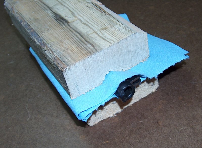
Precision woodworking.
I first practiced finish-reaming the chamber on the Roto barrel that came with my parts kit so that any "learning experiences" would not ruin the expensive barrel. I needn't have worried, as the process is much easier and less nerve-wracking than anticipated.
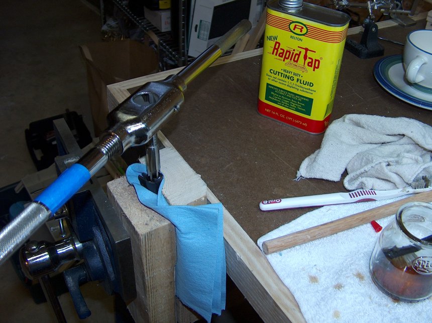
Tap that barrel.
The reamer is fitted to a tapping wrench, then coated with tapping fluid and inserted into the chamber. Some people talk about "dropping" a reamer into the chamber, but I can only assume that's a technical or colloquial term, since reamers are too expensive to just toss around.
Turning the reamer produces an interesting sensation as the blades carve chips of metal off the interior of the chamber. These chips show up on the blades when removed, and indicate which part of the reamer is doing the cutting. You can instantly tell when the taper has been removed from the chamber: The resistance in the wrench handles drops dramatically as the reamer stops cutting the edges of the chamber and starts biting into only the front of the chamber. At this point, the reamer is lengthening the chamber.
This is where I started taking it extra slow, checking headspace after every
turn of the wrench to ensure I didn't make the chamber too deep. I didn't go
through this laborious process for the test barrel, but made sure to take the
time for the Kart, stopping as soon as I hit a smidgen over mid-spec. (I was
aiming for reliability over accuracy.)
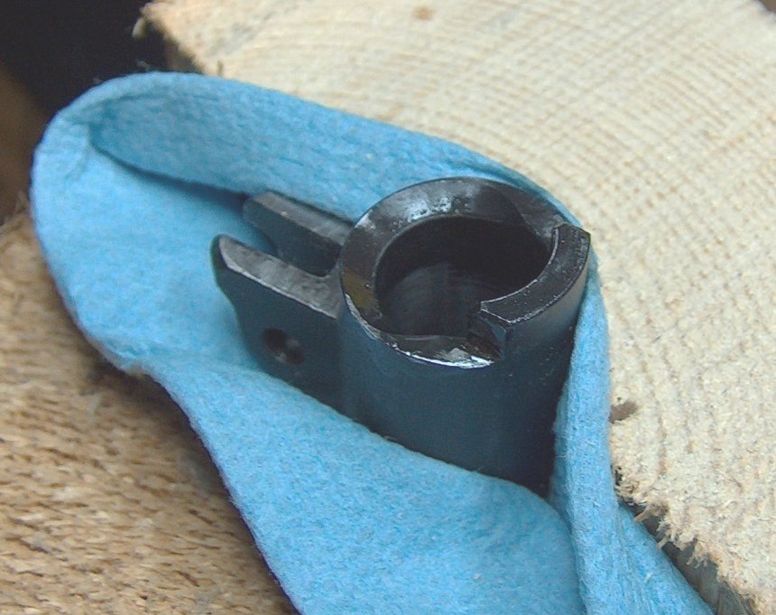
The ream-ains of the chamber.
As the above photo shows, a noteworthy amount of material is removed when finish-reaming. Although I didn't take any photos of the Kart barrel's reaming, the process worked every bit as smoothly, with one exception: The Kart's steel was noticeably harder than the Roto barrel's, requiring slightly more effort to turn the tap wrench.
The final turn of the tap wrench concluded the formal barrel fitting process. I say "formal" because this would not be the last time I had to work on the barrel. Despite this as-yet-unknown metalworking looming unseen over my head like a ninja with an anvil, fitting the barrel to the gun had been a long but ultimately rewarding endeavor. I thanked Lazarus for the advice and use of his tools, then spent the next four hours trying to get my hands to stop smelling like tapping fluid.
Canny readers of the last chapter may have been left wondering whether or not the laboriously hand-fitted barrel succeeded in fulfilling its raison d'etre?; to wit, the elimination of feed failures. Rather than continue to leave you in suspense while writing as pretentiously as possible, I'll cut to the chase and say the feeding problems were not fixed. The gun still experienced three-point jams.
This wasn't so much discouraging as intriguing. Theoretically, adding the Kart barrel had introduced a known good part, which meant that the problem lay elsewhere. In theory, theory and practice are the same; in practice, they're not. There was still a chance some aspect of the barrel contributed to feed failures.
A guy could spend an entire book writing about 1911 feed failures, and maybe somebody should. The 1911 platform has an undeserved reputation as being plagued by feed failures, and more than one self-proclaimed expert has bestowed upon it the ignominious title, "king of the feedway jam." This is far from fair. The M1911A1, as designed, is as reliabile as it is possible for a semi-automatic handgun chambered in .45 ACP to get. Poorly-executed copies of the design are prone to failure, but then I defy anyone to find a production semi-auto that would perform well when its feed ramp geometry is changed by several degrees, its spring weights unbalanced, and its ammo fed from magazines that diverge radically from the original design.
The good news is that 1911s operate on a controlled feed principle: Rounds are controlled at three or more points during every stage of the feed cycle. (Read this thread in M1911.org's gunsmithing forum for a detailed explanation of what happens during the 1911 feed cycle.) When done right, controlled feed produces a pistol that doesn't care if it's being fired upside down, sideways, held loosely, or all of the above while flying sideways through the air, John Woo style. Because the cartridge is "handled" extensively during feeding, ramp, breech face, extractor, and magazine dimensions are more critical than in guns whose feeding cycle is looser, and therefore more random. This is good news because when something goes wrong and a dimension is out of whack, feeding is deterministic and malfunctions repeatable enough to permit diagnosis and resolution of the problem in a logical and methodical manner.
Three-point jams are caused when the cartridge forces the barrel up prematurely, wedging it against the slide and bringing the feeding process to a crashing halt. The cartridge is jammed solid at three points: the nose rests against the roof of the chamber, the brass rests on the lower lip of the chamber, and the rim sits under the extractor. Common causes include the bullet striking the barrel ramp too low, the bullet striking the chamber roof too far back, the rim being unable to rise under the extractor, or any combination of the above. Technically, these aren't even the primary causes, as symptoms like a bullet hitting the barrel ramp too low or the chamber roof too far back are themselves the result of dimensional variance that is the actual cause of the problem.
It was a complicated and thorny issue, so I started by eliminating the most common cause of feed malfunctions: the magazine. I've already written an article about 1911 magazines, so I won't go into any additional detail on the subject other than to say that using the right kind of magazines (hint: They probably won't have someone's name on them) is often the simplest and most correct fix. In this case, though, it was a non-starter: Using Colt hybrid mags reduced the frequency of jams but didn't even come close to eliminating them.
The extractor passed all tension tests and was properly beveled, and the breech face was reasonably smooth and even; they could be crossed out as well. That left something in the geometry of the frame and barrel ramps as the most likely cause. During feeding, the cartridge is pushed forward and the bullet dips into the feed ramp, striking it just below the lip, then arcs up and over the lip of the barrel ramp and into the chamber. Actual contact between the cartridge and the barrel ramp should be minimal, and the bullet should touch the frame ramp as high as is possible while still maintaining this feed principle. The subtler the hop from frame to barrel, the smoother the feed. Conversely, excessive contact with either ramp results in clunky feeding at best, and is often symptomatic of a jammer.
In this case, copper marks from bullets showed up quite a ways down the frame ramp and roughly halfway down the barrel ramp. I shared these facts and the following photo with the M1911.org gunsmithing photo and asked if anything jumped out at them as a possible cause:
This should work fine, right?
Several people pointed out that my barrel ramp had a sharp edge at the top. The Colt spec calls for a 0.02" radius at this point to assist the cartridge in clearing the barrel ramp. 1911Tuner mentioned that the barrel ramp looked like it sat too close to the frame ramp; spec calls for a gap of at least 1/32" here. Lazarus' experience with 1911 frame bridge dimensions led him to suggest I check for excessive frame bridge height.
Whew. Let's take these one at a time.
First up was the easiest fix, and one that needed to be done anyway: adding the rollover radius to the barrel ramp. At two hundredths of an inch, this is a very subtle clearance designed just to provide a little leeway for cartridges on the way to the chamber. Here's an example of the radius (actually a bevel in this case) on the barrel in my Springfield Armory Mil- Spec:
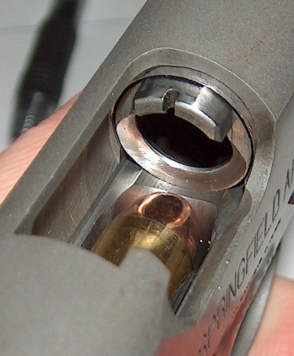
A slightly more beveloped barrel.
In addition to the radius/bevel, note the gap between the frame and barrel ramps: much larger than in the project gun. The barrel ramp is also much steeper than the one on my Kart barrel; in fact, it's pretty clear that the barrel ramp is not designed for much cartridge contact at all.
Putting a bevel on the barrel ramp probably takes a tech in Imbel's Brazilian factories about ten minutes at the most. Naturally, I spent an hour doing the same thing with some 400-grit sandpaper wrapped around a pen. The time taken could have been reduced by an order of magnitude if a Dremel had been involved, but that would have made it too easy to go too far too quickly. If taken too far into the chamber, the rollover radius can compromise case web support and cause a brass rupture. Taking it slowly and checking web support against a marked case ensured that chamber support was only reduced by a fractional amount. (Sorry I don't have any pictures, but I got so focused on the process that I forgot to take any.)
Next up was the frame bridge, the raised section of the frame between the magwell and frame bed, which is the lowered section aft of the dust cover. Lazarus pointed out that an oft-overlooked factor in feed reliability is the height of the frame bridge, which can contribute to three-point jams through two mechanisms. First, as the frame bridge rises higher relative to the top round in the magazine, rounds fed off the magazine will strike the frame ramp lower and therefore encounter the barrel at a more acute angle. Second, if the frame bridge is too high, the barrel will strike the bridge during link-down before the barrel's lower lugs make contact with the vertical impact surface. Not only does this put incredible stress on the slide stop pin, the link, the link pin, and the lower lugs (breakage of one of these parts is inevitable), but it also leaves the link in tension while the barrel is resting on the bridge. The balance of forces favors upward motion by the barrel, so a round striking the barrel ramp too low can easily induce a three-point jam.
This is a nice theory, but was it relevant to the problem at hand? Let's take a look.
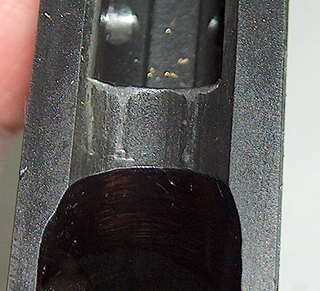
I think the barrel wants to go a little farther down.
The frame bridge showed definite hard contact from the barrel. Smearing a very thin layer of lipstick on the lower lugs and cycling the gun showed no vertical impact surface contact. If you look closely at the photo, you can see casting ridges on the frame bridge; my theory was that these ridges increased the height of the bridge just enough to hang up the barrel and prevent VIS contact. If that was the case, removing the ridges would fix things.
Lowering the frame bed requires very careful measurement and leveling and is best done with milling machine and years of experience therewith. Yet here we are. Actually, what I was doing was just dressing the bed to remove high spots and battering. Still, I was careful and took my time; in fact, taking one's time is a natural consequence of removing weapons-grade chrome-molybdenum steel using only 400 and 600 grit sandpaper.
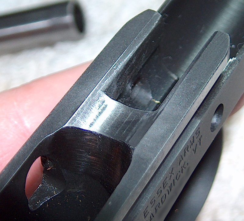
Gundon bridge is filing down.
I lowered the ridges until they were almost flush with the rest of the frame bed and only the seams were visible, then tested for VIS contact again. No cigar, although a few tiny dabs of lipstick on the VIS suggested I was getting close. I evened out the surface so that the seams were gone, then took it down just a smidgen more to remove marks where the lower edge of the barrel ramp had left marks.
Bingo.
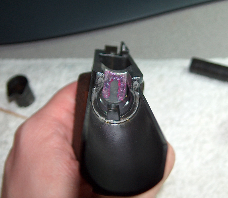
A firm smack leaves lipstick marks.
Barrel link-down was now geometrically correct; if the barrel ripped itself apart in 5,000 rounds, I'd have to blame something else. I finished things up by using the grinding wheel on my Dremel to put a bevel on the forward edge of the frame bridge, as specified by the original blueprints. (There had been a bevel on there to start, but battering from the barrel and the lowered bridge had combined to effectively eliminate it.)
As far as feed reliability went, radiusing the top of the barrel ramp and lowering the bed made a noticeable improvement... but didn't completely fix the problem. Instead of jams on every second magazine or worse, the frequency dropped to once every third or fourth mag and became more predictable: When a three-point jam occurred, it was always in the last three rounds of the magazine. These are the rounds where the magazine spring is at its weakest and the cartridge has the least support as it's stripped from the mag, thereby increasing the chances of the round entering the feed cycle at a more acute angle.
It looked like Tuner's observation of the barrel/frame ramp gap and the shallowness of the barrel ramp had been spot on. I hadn't doubted him, but the specter of moving the barrel ramp back had been scary enough to justify seeking less drastic solutions at first.
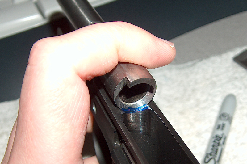
Measuring the gap.
Still, there was no denying it: The barrel sat too close to the frame ramp. Smearing the gap with a Sharpie while the barrel was held in position permitted pretty accurate measurements showing that the barrel/frame ramp gap was only a little more than half the minimum specified amount of 1/32". It had started on the narrow side, but lowering the frame bridge had brought the frame ramp in slightly, dropping the gap to just over 1/64".
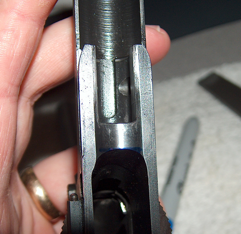
The thin blue line.
1911Tuner advised me to use the method described in Kuhnhausen's first 1911 book to set the barrel ramp back. This involves using a smooth mill file at a 45 degree angle opposite the slope of the barrel ramp to take the ramp back until the desired gap is achieved. This will leave a flat wall at the base of the ramp, which can then be scraped to make a new, continuous surface. If done right, the top of the ramp doesn't move in much, if at all; it just gets steeper. Therefore, if done right, the process doesn't compromise case support.
"If done right," is the operative term here. Despite Tuner's assurances that someone with modicum of ability could perform the operation, I worried that a machinist and a computer programmer might apply different definitions of "modicum" to metalworking skill. Nonetheless, I procured a scraper and proceeded.
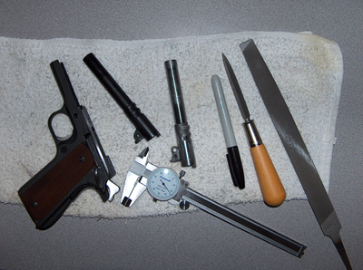
Everything you need to mangle your barrel.
Fortunately, I still had the sacrificial Roto barrel on which I'd practiced finish reaming. Once again, it would serve as the testbed for a scary procedure. In practice, it really wasn't that bad. I laid the mill file on the bench and dragged the barrel over it to file back the bottom of the ramp, checking the frame/barrel gap after every stroke, then clamped it in a vice for the scraping.
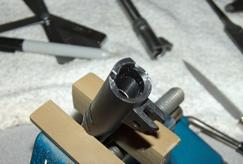
Scrape expectations.
Using a scrape is where I can really see experience vastly improving the final result. Scraping away metal takes a steady hand and some degree of strength, and works best with long, sure sweeps. I managed to get by, but the final result required some sandpaper cleanup. Just like I'd noticed the difference in effort to turn a reamer between the Roto and Kart barrel, the amount of effort required to scrape the barrel was distinct. The upshot of that was the Kart barrel, which I worked on second, didn't turn out as well as the first try on the Roto barrel. Sandpaper to the rescue once more. While I was at it, I restored the rollover radius that scraping the ramp had partially removed.
I'd like to say that taking the barrel ramp back fixed the feed issues for good, but that would be a lie. The gun saw a marginal reduction in jams, but not a complete cure. To paraphrase Sherlock Holmes, "when you have eliminated all probably explanations, whatever remains, no matter how improbable, is likely to be the first thing you should have checked." It was time to look at the frame.
To be fair, the possibility that the frame might be at fault had been a consideration from the start; however, I didn't want to spend money sending it back to the manufacturer as long as there were options I could pursue on my own. At this point, though, there was literally nothing more I could do. If the frame was to blame, then it was likely the ramp was either too steep or too shallow. (As opposed to excessively within tolerances, I guess.) The fact that the dummy rounds I'd been using to test chambering showed noticeable bullet setback suggested the ramp was too steep; on the other hand, having to move the barrel ramp back suggested the frame ramp was cut farther in than it should be, and was therefore too shallow.
If only there were some way to know for sure.

Angling for a factory fix.
I didn't have a machinist's protractor on hand, but I managed to scrounge up a woodworking protracter and trimmed down the measurement arm to the point it would fit in the magwell. The block supplied with my Kart barrel fitting kit served as a nice reference surface when rested on the rails. Although this cobbled-together setup only yielded accuracy to the nearest degree or so, the problem was big enough to be detectable even at that coarse granularity.
Specifications for the M1911 pistol degree that the frame ramp must be cut at an angle of 31 degrees, 30 minutes with absolutely no variation allowed. Mine measured approximately 27 degrees: too steep. (Ramp angles are measured from the vertical plane; that plus the different ways that "steep" and "shallow" could be interpreted was the source of some confusion on my part.) The blueprints also require the magwell to be cut at between 14 degrees, 45 minutes and 14 degrees, 55 minutes. Mine was about 17 degrees, which made it far too shallow. My magazine was tilted toward the frame ramp, which was itself too steep. Cartridges were being fed forward at a decreased angle, smacked into the too-steep frame ramp, then levered up and over the barrel ramp into the chamber. The downward angle on the magwell was making my hybrid mags feed like wadcutter mags, and my wadcutter mags feed like crap.
The simple solution would be to go out to the garage, fire up my mill, and recut the ramp. The only obstacle to this simple plan is the fact that I don't own a mill (yet). (Note to my wife: Just kidding!) (Note to everyone else: Not kidding, it arrives Thursday.) Inasmuch as I lacked the tools to fix this myself, and also seeing as how dimensions out of spec to the point that they compromised feed reliability constitute a big fat defect in construction, it had to go back to Essex.
Easier said than done. Getting ahold of Essex Arms by telephone is like pulling teeth, but I finally managed to get the go-ahead to send the frame in. UPS doesn't recognize Essex's address, but Fedex does, and I was eventually able to convince a carrier to let me give them money in exchange for transportation of the package. About a month passed before the frame was returned with a recut ramp and new bluing.
This section started off with anticlimax (the gun didn't work), so it might as well end the same way: With the fixes to the frame, the last of the feeding problems were put to rest, although I still believe this 1911 is running closer to the edge of the reliability envelope than most. Testing at the range ran into the occasional jam when wadcutter mags without sufficient spring support were used. That's likely the magwell angle coming into play; more extensive testing with good hybrid mags is required to determine whether the issue can be abrogated with good mags or will require eventual frame replacement to ensure reliability. I may be forced to shoot a lot of ammo in order to find out.
Oh darn.
Interspersed with the various gratuitous acts of firearm modification performed in pursuit of feed and extraction reliability was some work on the safety features. If this gun could be rendered reliabile, I intended to carry it, and carrying a firearm is much more pleasant when it's not inadvertently putting holes in its owner and/or the surrounding scenery.
The most important safety feature is a properly-functioning firing system, but that issue is dealt with later. This section is more concerned with the manual safety and the firing pin. The grip safety, though slightly rattly, functioned just fine so I didn't mess with it.
The manual safety (a.k.a. the thumb safety or safety lock, depending on whose nomenclature you're using) was a different story. It was very light, flicking on and off with almost no effort. This was even with the tiny pre-A1 safety tab, which requires all force used on the safety to be focused on a small area. Under advisement from 1911Tuner, I replaced the plungers and connecting spring with a Colt plunger assembly.
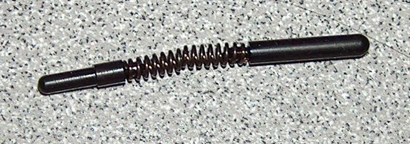
Taking the plunge.
Installation of the Colt parts produced a noticeable improvement; the spring I had been using must have been seriously fatigued. However, the safety still didn't have the positive "snap" I was looking for. Given that the problem persisted with known-good plunger parts, that left something in the catch itself as the source of the light engagement. I took a closer look, as did the denizens of the M1911.org gunsmithing forum, where I posted the following image:
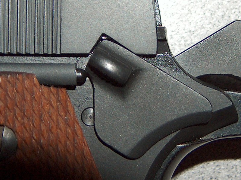
What's wrong with this picture?
There were several theories advanced as to what was going wrong with the safety. A few people keyed on the incomplete alignment with the safety lock cutout in the slide, theorizing that the catch couldn't rise high enough to let the plunger all the way out. Unfortunately, the safety wouldn't travel any higher with the slide removed, so that idea had to be scuppered.
It finally occurred to me to compare the safety on the project gun with the one on my Springfield Armory Mil-Spec. The Mil-Spec safety took a great deal of effort to snap off, so perhaps a look at the differences between the two would shed some light on the issue.
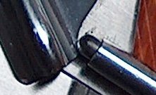
Seen this way, the source of the problem was pretty clear: The shape of the safety wasn't letting the plunger out far enough, so the safety gained a high amount of mechanical advantage over the curved end of the plunger. (Another factor in the Mil-Spec's stiff safety was the fact that the plunger tube hadn't been reamed out far enough, so the spring pressure was pretty intense.)
I decided to alter the geometry of my safety to let the plunger come out a bit farther. Unfortunately, altering the geometry of a curved surface in a controlled and aesthetically-appealing manner turned out to be beyond my level of skill.
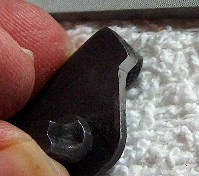
Yet another example of masterful metalworking.
As you can see, I ended up putting a metal shelf in the safety. While this worked great for letting the plunger out, it also increased the aforementioned mechanical advantage to the point that it was completely impossible to thumb off the safety. Technically speaking, this constituted success, as I'd increased the stiffness of the safety; realistically speaking, I ordered a replacement part.
By way of a brief aside, it's really difficult to find normal thumb safeties for the 1911. If I'd been in the mood for an extended tactical high-ride ambidextrous safety catch with aircraft-carrier-style rectangular pads large enough to land an F-18, it would have been a simple matter to locate one. Instead, I spent quite a bit of time tracking down a latch by a no-name manufacturer. My patience was rewarded by the delivery of an A1-style thumb safety, which dropped right into the frame and functioned perfectly.
Let me repeat that, just in case you glossed over it: The thumb safety dropped right in without any fitting. Once in place, it worked from the start. It prevented sear motion, required positive force to snap off, and fit the pin hole perfectly. Total time for installation was approximately two seconds. Such simple and painless addition of a part to the gun was so completely unprecedented that I am forced to conclude that it was a statistical anomaly and therefore never happened.
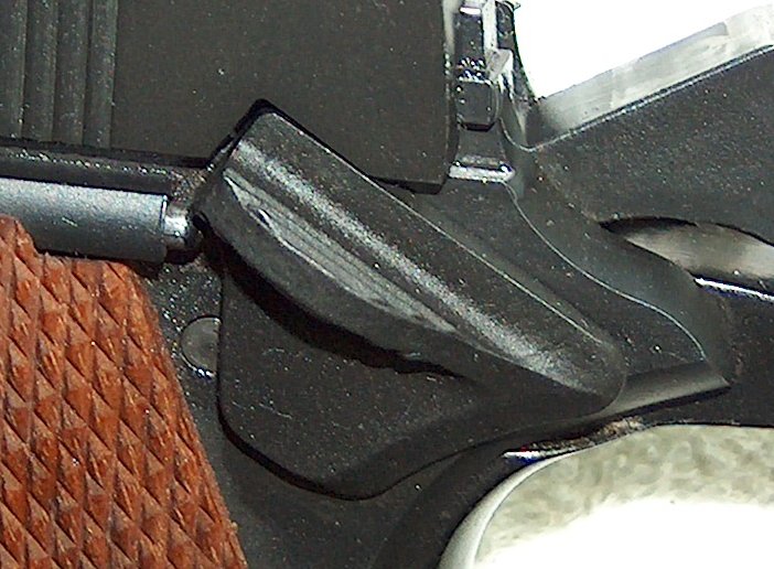
Just a trick of the numbers.
Okay, so there was one snag: a snag of metal that stuck up near the outside edge of the safety where the ridging was simply cut short without any rounding. It was located in the perfect position to dig painfully into one's thumb when swiping off the safety. Sufficient safety swiping served to inflict a fairly nasty blister, proving once more that guns hurt people, even when used safely.
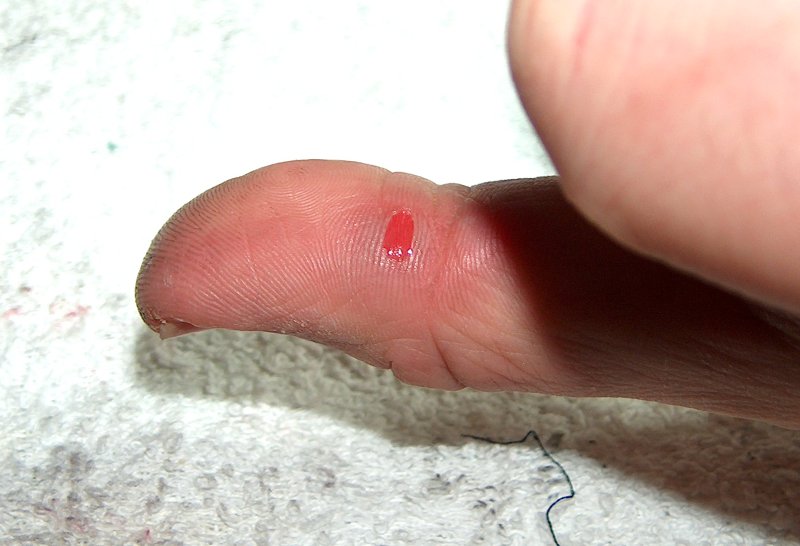
Still slightly less painful that not using the safety.
Fortunately, help was at hand in the form of a #2 Swiss Cut pillar file. Filing down a sharp burr is more my speed, anyway. I took off the sharp edges at the front and rear, both top and botthem, then put a comfortable radius on the top. Problem solved. So this was what it felt like to successfully improve a safety by using a file.
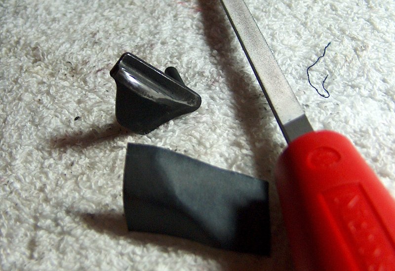
A kinder, gentler safety.
There was, of course, the remaining issue of exposed metal, but that would be the work of a few moments with the trusty bottle of cold-blue solution. After cleaning and degreasing the part, I swabbeded on some cold blue...and absolutely nothing happened. Curious, I repeated. No effect. Thus ensued an increasingly frenetic frenzy of degreasing and reapplication of bluing, all to no end. I honestly felt like I was losing my mind until it occurred to me that the part was probably made of stainless steel or some corrosion-resistant MIM material with a spray-on coating.
Fine. Two can play that game.
You can run, but you can't hyde.
I acquired a can of Brownell's Aluma-Hyde to refinish the safety. As its name suggests, it's designed mainly for refinishing aluminum parts, but claims equal efficacy on steel, plastic, or wood. What appealed to me was the fact that Aluma-Hyde is not a bake-on finish, but simply requires a couple days to cure. Also, it claims to adhere well with minimal surface prep; as someone who does not yet own sand- or bead-blasting equipment, this is naturally a plus. I did, however, sand off some of the coating and even out the surface with steel wool to minimize any layering from the spray.
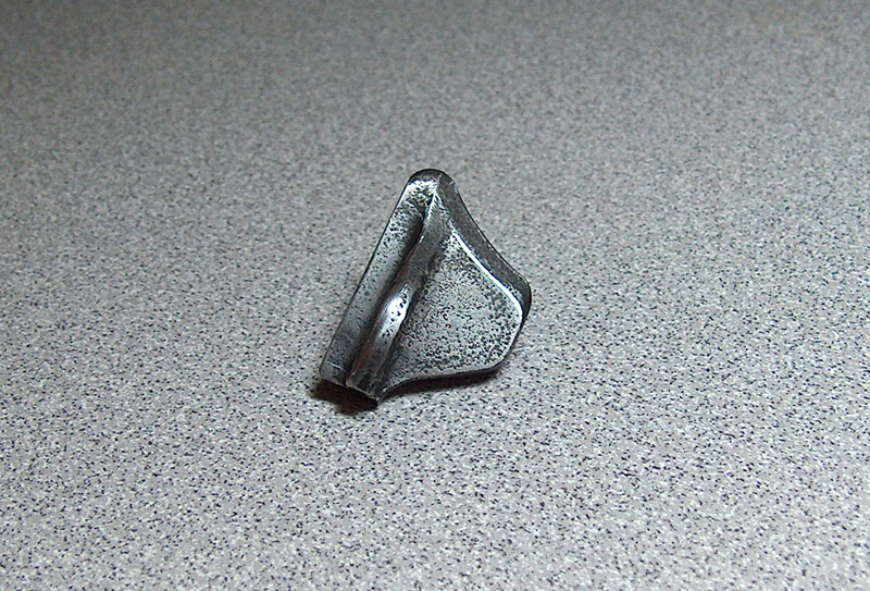
It's always the darkest just before dawn.
Per the instructions on the can, the coating cures fastest at between 70 and
90 degrees Fahrenheit. Fortunately, I happened to have a nice warm Saturday
free. Degreasing the safety took a couple quick blasts of Gun Scrubber; I let
it dry while I assembled a support for the safety out of a scrap of cardboard.
It figures: The first time I actually want a piece of styrofoam, there's none
to be found lying around in large, inconvenient hunks that take up all the
space in the garbage cans. The safety is supported by its pin; if I cared
about uniform coloring of the part, I'd have to do the painting in two
installments, one for each side. Fortunately, I don't care.
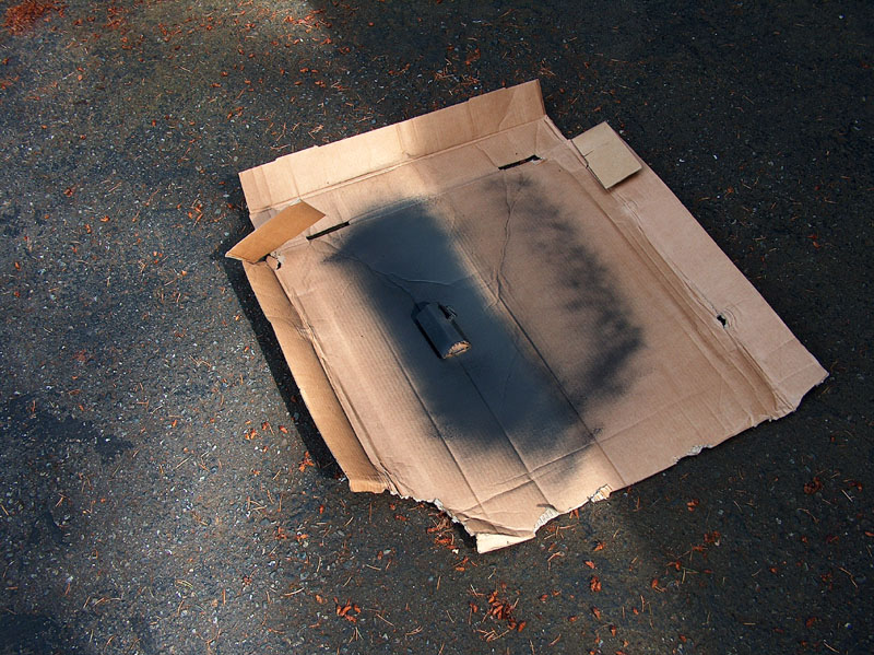
Precision firearms finishing.
I sprayed on the Aluma-Hyde and let it sit for the thirty minutes recommended before handling. Thirty minutes is also the cutoff point for recoating before the manufacturer recommends letting the finish cure for several days. I should have taken a closer look before that point, as it turned out that I missed a couple spots.
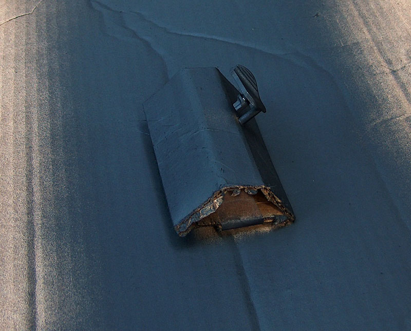
Not quite finished.
This necessitated waiting a couple days and repeating the process. This time, though, things turned out much better.
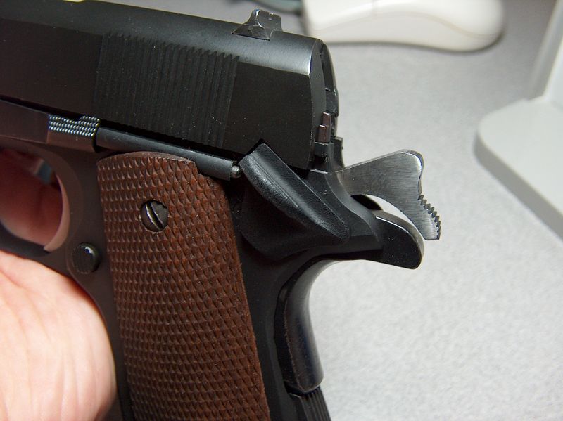
No longer as paintfully ugly.
Another concession to safety I made was replacement of the firing pin. The standard 1911 firing pin is quite safe, provided it's paired with a sufficiently strong firing pin spring; if not, the inertia of the firing pin can carry it forward when the slide slams into battery at the end of the recoil cycle. A moderately weak spring, like the one that came with my parts kit, can let the firing pin far enough forward to leave marks on the primer. These are disconcerting, but far preferable to the results of a spring so weak that the firing pin is carried forward during chambering with enough force to ignite the next round. The best possible outcome in this situation is a brief but terrifying full-auto experience; however, the firing pin's inertia doesn't care whether or not the gun is in battery, so the worst-case scenario involves an explosion.
These are compelling reasons to replace one's firing pin spring regularly. If you use Wolff gun springs, you're set: Wolff includes an extra-strength firing pin spring with their recoil springs, making it convenient to change both at once. I went one further, though, and bought a titanium firing pin.
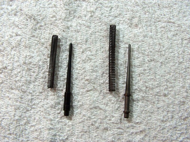
Pinning my hopes on the lightweight.
The pin I bought is the same one used by Springfield Armory in their 1911s in order to get around California's asinine "drop safety test". It comes with an even stronger firing pin spring than Wolff's; the combination of the light pin and very strong spring forces SA to use a much heavier-than-normal mainspring (I've heard 28 pounds) in order to drive the hammer hard enough to prevent light primer strikes. A standard 23-pound mainspring isn't enough to get reliable ignition with both the titanium pin and heavy spring. I switched to a Wolff firing pin spring; at first, it seemed to have the seem light strikes as the SA spring, but once the spring took a set it became perfectly reliable.
Some may question the necessity of using an exotic metal for the firing pin, and it's a reasonable question. I've read tests wherein the tester used a primed, empty case and an old slide assembly to try to ignite the primer from dropping the slide on its muzzle, only to be unsuccessful for any drop less than twenty feet. Running such tests myself might assuage any worries, but I lack a slide and barrel I'm willing to abuse in such a manner. While I wouldn't go so far as to use a 1911 with a firing pin block, a titanium firing pin is an acceptably unintrusive way of increasing the safety margin.
Besides, it's one of the few parts that didn't need fitting.
This 1911 just generally got it backwards when it came to the question of what went forward and what went back: Its feeding issues showed a reluctance to move rounds forward to the chamber, a reluctance that was not at all missing during extraction, when it enthusiastically tossed casings forward. The feeding issue had been largely resolved, which left the forward extraction issue requiring attention. Now I'm given to understand that schucking cases forward is expected behavior for some assault rifles, but it's in no way desireable for 1911s. Even though the extraction issue had never caused a jam, I like my casings tossed neatly behind me where they can be collected at leisure instead of being forced to frantically grovel for them forward of the firing line during a cease-fire.
I had already eliminated some possibilities for what could be causing the problem, but I was still stymied. What finally broke the confusion was a chance glance at the breech face during a range trip: There was a streak of brass on the left shoulder of the breech face where I'd widened it. Some hand cycling revealed that I hadn't widened it quite enough, and some residual filing marks were grabbing the left rim of the round during extraction. I cleaned up the remaining filing marks and, while I was at it, widened the breech face a bit more, to 0.490". This is really on the wide side for the breech face (the usual max is 0.488"), although I've been told some gunsmiths will take it this wide. Seeing as how I was actually getting friction from the case rim, I felt the extra width was justified.
Okay, maybe not that justified. Filing the breech face wider improved the forward extraction slightly, but didn't come anywhere close to curing it. The best theory I could come up with was a dimensional conflict in the slide or frame: Maybe the slide couldn't come back far enough, or the frame was built such that the ejector was placed too far back. If this was the case, fitting an extended ejector might clear things up. I'd had very good results from my Mil-Spec's extended ejector, so maybe that would do the trick here.
I don't usually like to flail around in the dark like this, but with no other leads, changing the ejector would at least let me check one option off the list. Also, removing and replacing the ejector was one of those things I'd hoped not to have to do. I wanted to fix the issue more than I wanted to avoid installing a new ejector, though, so I ordered a Springfield Armory extended ejector and got to work.
In theory, the process would be relatively simple; Kuhnhausen pretty much lays it out step by step in his first 1911 manual. In practice: haha.
First up was removing the roll pin holding the ejector in place. This was relatively trivial to do with a roll pin punch, although it should be noted that driving out the ejector pin works much better if you don't have a solid surface behind its exit point.
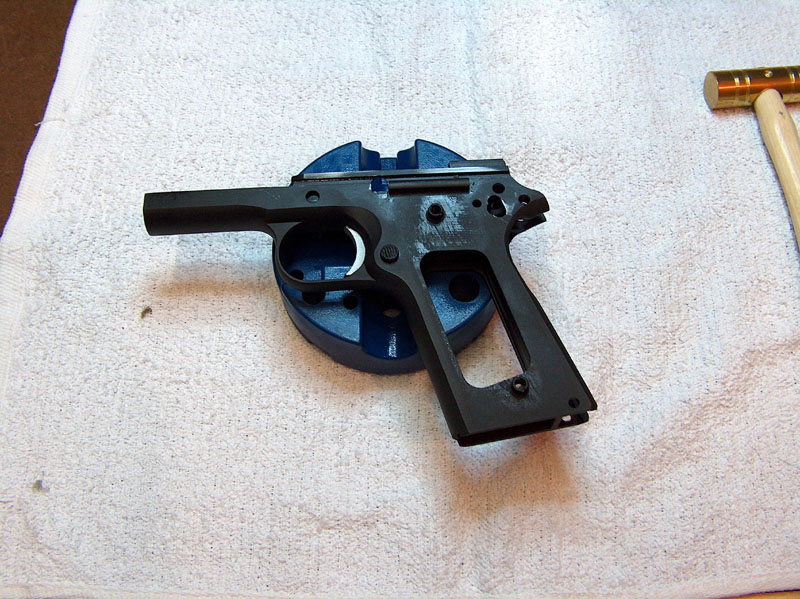
It looked easy at this point.
With the roll pin removed, the only thing holding the ejector in place was a little bit of friction and I was able to quickly pluck the ejector from the slide.
Just kidding! That ejector felt like it was welded in place. I tried budging it with vice grips, to no avail other than mutilating the ejector's surface and putting a small ding in one of the rails. Finally, I used Kuhnhausen's recommended ejector removal method:
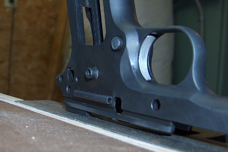
The best advice for removing an extractor.
I ended up reopening the jaws and moving the gun down so that the vice could close on the thicker part of the ejector body. I had to seriously crank the vice closed in order to keep the ejector from simply wiggling out of the jaws when force was applied to the frame. Even then, it took an enormous amount of effort to pull the ejector loose. Fortunately, good ultimately triumphed over evil. I left the old ejector sitting beside the new while I applied bandages to the injuries inflicted during its removal.
Long rear post on the new ejector.
Tentatively inserting the new ejector into the frame's post holes (I didn't want it to get sucked in and retained by whatever malevolent force kept the first one in place) showed that the new ejector's rear leg was too long. A few minutes' work with a Dremel's cut-off wheel fixed that.
Less of a leg to stand on.
The slightly coppery color of the ejector under the parkerization suggested it had been heat-treated, so I was concerned about ruining the temper by heating up the part too much during cutting. To prevent this eventuality, I made sure to touch the ejector while I trimmed its legs: The metal would get too hot to touch before the heat treatment was degraded. I finished the work on the leg by smoothing the cut-off base with a mill file and putting a mild bevel on the post's edge to prevent burrs from catching or forming in the channel.
If you look closely in the above photos, you'll notice that the old ejector has a small cutout in its front leg to clear the ejector pin, whereas the new ejector does not. Kuhnhausen recommends inserting the new ejector and then using a punch pushed through the ejector pin hole to mark the leg where the ejector pin will go. This works pretty well. What didn't work as well was using a round file to add the cutout; the radius of the file was just too large. Fortunately, I noticed this before I cut too deep and finished by using the edge of the cutoff wheel to slowly nibble away material, checking the hole alignment frequently, until 90% of the hole was clear. I left a little bit of material interfering so that the tension of the pin forced into place would hold the ejector firmly.
Tapping the pin in was uneventful, and I was left with this:

A most fitting conclusion.
The ejector sat rock-solide in the frame and cleared the slide perfectly. But did it do what it was supposed to? Only a trip to the range would reveal the truth.
A trip to the range did indeed reveal the truth. The new ejector fixed 95% of the forward-ejection, but even more importantly showed the root cause of the problem. During the test firing, I'd shoot a mag of ammo, find where the ejected shells landed, gather them up, and then repeat. Several magazines in a row showed casings landing in the exact same scattered locations. I actually thought to myself, "hmmm, the brass is going all over the place, but the specific locations it's landing are regular as clockwork." At that instant, a tiny lightbulb flickered fitfully to life above my head. Clockwork: The extractor was clocking in its channel, rotating under recoil during the feeding cycle. This was the cause of the erratic ejection, and probably what was responsible for the forward ejection. The extractor hook was the right depth if properly lined up, but when tilted at an angle, the hook depth would be short enough to make it fail to remove the case from the gun with sufficient vigor.
The ideal solution would be to acquire an overside firing pin stop that would hold the extractor steady; perhaps even a new extractor was in order. Even though the extended ejector wasn't strictly necessary, it had helped me track the problem down. More importantly, it reduced the frequency of forward ejection to the point that I feel comfortable closing this chapter here, and leaving any notes about fitting a firing pin stop for an addendum to the article.
In addition to feeding and extraction issues, there was the minor issue of the trigger, which was a heavy, gritty, stagy atrocity. I wasn't suprised that it was bad; that's to be expected when tossing random fire control parts into the gun without any fitting. What was surprising was just how bad it was. I couldn't even get an accurate assessment of the gun's accuracy due to the excessively heavy trigger.
But exactly how awful was it, anyway? I resolved to find out, but since I didn't have a trigger scale, I was forced to improvise:
Precision trigger pull scale.
I tied down the grip safety and attached an empty milk jug to the trigger. The plan was to pour in water until the trigger tripped, then measure the volume: A pint's a pound, the world round. Alternately, a milliliter's a gram, but I don't give a damn; this is America.
While spitting out cunning aphorisms, it should be noted that in theory, theory and practice are the same; in practice, they are not. In other words, the milk jug trigger scale didn't work well at all. I got very inconsistent readings and water all over my shoes. My backup plan involved getting Lazarus to test the trigger with his digital trigger pull scale, a minor increase in technology over my method. Thus tested, the trigger was shown to have a delightful 10.25 pound pull.
I'm no trigger prima donna, but ten and a quarter pounds is a bit excessive. Fortunately, help was at hand: In addition to having a trigger pull gauge, Lazarus also had good working knowledge of how to do fit a hammer and sear, and was willing to walk me through the procedure. Although my first run through used his tools, I was so excited at the demystification of the process that I went out and bought my own set of equipment.
Just a few simple tools.
The easiest tools to acquire were the glasses, both magnifying and piece of. The magnifying glass is useful for examining hammer/sear interaction (more on that later); the piece of plate glass makes a nice smooth surface for knocking down high spots on the sides of flat parts like the sear and hammer.
Most of the abrasive heavy lifting is done by the stones, though. From bottom to top, these are medium, fine, and extra-fine stones.
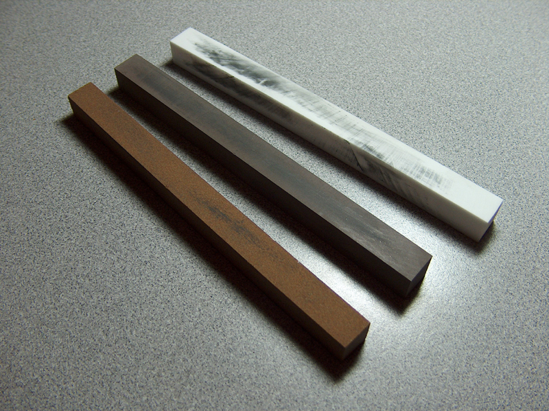
Bottom to top: dirty, filthy, and extra-filthy.
The idea is to use these in sequence on the sear angles. The medium stone shapes the metal, the fine stone refines the shape and knocks down high points, and the extra-fine smooths the surface. Of course, the ability of these stones to apply precise angles to hardened steel would be entirely theoretical if they couldn't be controlled or supported in some way. That's where the sear jig comes in:
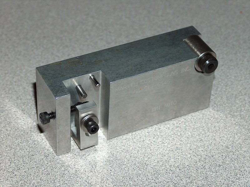
The jig is up!
This is the Marvel sear jig I bought from Brownells. The entire point of a sear jig is to hold the sear at a precise angle so that the engagement surface can be stoned at an equally precise angle. Precision is the name of the game here, as the mating surfaces of the sear and hammer interact at angles and sizes smaller than the human eye can detect. In fact, some pistolsmiths who do trigger jobs for bullseye shooters use microscopes to examine the engagement between the hammer and sear.
My methods were slightly less precise:
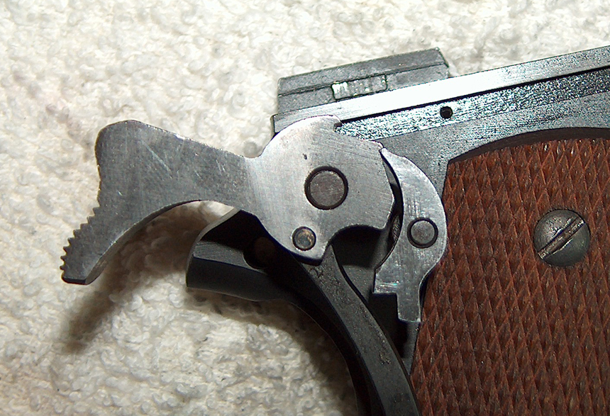
An engaging spectacle.
Spectacles are what you need to get a good look at the tiny slivers of metal responsible for holding the hammer in place. I tried taking a photo of the view through a magnifying glass lens, but attempts to do so only succeeded in driving my camera's autofocus feature insane.
The pins on which the hammer and sear sit are special pins that fit through the standard hammer and sear pin holes, but feature flat bushings and extended shafts so that the interaction of hammer and sear can be seen exactly as it will occur inside the frame. The downside to frame pins is that viewing the opposite side of the hammer and sear requires removing everything and setting it up in reverse on the other side of the frame. You can get pin blocks, which are small slabs of steel with pins inserted in at the distances specified by 1911 blueprints. Cutouts in the slab make looking at both sides of the engagement as simple as turning the block over. The downside to pin blocks is that the location of the pins in this block doesn't necessarily say anything about the pins in one's frame. The best compromise are pin block with adjustable pins to permit fitting to the eccentricities of a given frame, but those can get pretty pricey. Since I was only interested in a carry-grade trigger of moderate to heavy weight, the frame pins would work fine.
(Note: I define "carry-grade" and "moderate to heavy weight" to mean a trigger in the five to six pound neighborhood. Like I said, I'm not a trigger prima donna and strongly question the wisdom of putting a sub-four-pound trigger on a 1911 for reasons of durability and safety; compromising the latter is the inevitable result of compromising the former in pursuit of a trigger pull better suited to a revolver than a semi-auto. But that's a rant for another day when I have some unassailable diagrams.)
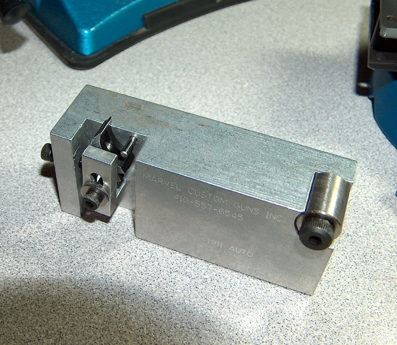
The primary concern.
Setting up the sear in the jig is actually pretty simple, consisting of putting the sear in place, rotating it clockwise until the lower legs are stopped by the screw on the left, then locking it in place. The left-hand screw defines the steepness of the primary sear angle, which must be set before locking things up.
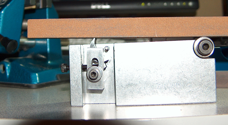
True grit.
Once the sear is positioned correctly, the stones are used to first shape, then smooth the metal surface. Although the jig is mostly a giant block of aluminum, the roller is steel to ensure it isn't chewed to bits by the stones as they roll over it. Force must be applied evenly and consistently; I ruined a sear by not placing consistent force on the entire stone, causing one side to be eaten away prematurely. Reshaping the primary angle requires frequent checks for evenness and the progression of the reshaping. As the new surface takes form, the line of filed metal will move toward the base of the sear nose; when it hits that base, it's time to stop filing. (Removal of too much material from the sear impairs its ability to catch the hammer hooks.) This means that you don't get many, if any, do-overs. Personally, this didn't make me nervous at all.
Nope, not even a little.
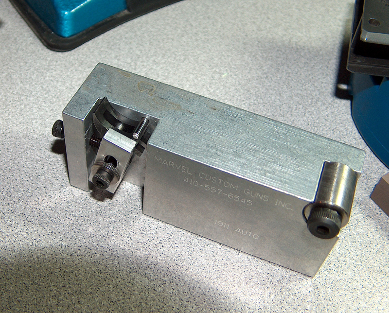
Secondary importance.
The secondary sear angle is determined only by the shape of the sear itself when using this jig: Unclamping the sear lets it rotate back until it's stopped by a fixed bar. This isn't a big deal because the secondary angle isn't as important as the primary; its job is just to help the sear get out of the way of the hammer.
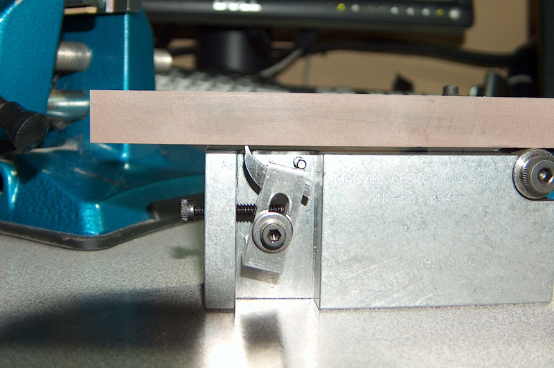
Smooth operation.
The fitting itself is a finicky and tedious operation of setting and smoothing angles, comparing with the hammer hooks, assembling, testing the pull, and repeating until the trigger is to one's satisfaction. There's also the optional step of going too far, creating a trigger that trips when an extra-heavy neutrino runs into it, and starting all over again. It's like setting the seating and crimp on a reloading press, except there's no bullet puller to fix things if you go to far.
The final result was a trigger pull that, the more I thought about it, felt far too light. I was somewhat irritated by having overdone things again, and even went so far as to order another sear to replace the one I had clearly screwed up. If I had to guess, I would have said the trigger was in the low four pound range, maybe even high threes.
Then I measured the pull on a trigger gauge: 6.5 pounds. It just goes to show that either I have no idea what triggers weigh, or that smoothness and crispness contribute more to a light-feeling trigger pull than the actual gross weight.
As you've probably already noticed, this chapter doesn't contain much in- depth analysis of trigger jobs. (I don't even touch on hammer prep.) This is for two reasons: First, this is an account, not a guide, and second, the theory and application of 1911 triggers is a huge subject, big enough for an article all its own. I was going to go in-depth into sear face angle, hammer hook depth, positive and negative engagement, and all the fun, mind-numbing details guaranteed to cure insomnia. I even started drafting some diagrams, but then a realization hit me: This account is huge, much larger than I ever anticipated making it. (Of course, there was more involved in this build than I ever expected.) Did I really need to make it much longer?
As evidenced by the lack of further information on 1911 triggers, the answer is no. I'll do a more extensive writeup on 1911 triggers sometime in the future, so check my articles index for the appearance of said writeup if the subject interests you.
The trigger pull problem had now joined the feeding and extraction problems in the annals of solved issues. With no further parts to add or problems to solve, was this the end?
The final part installed in the 1911 had been the extended ejector. The final part of this writeup is showing you pictures of the completed firearm.
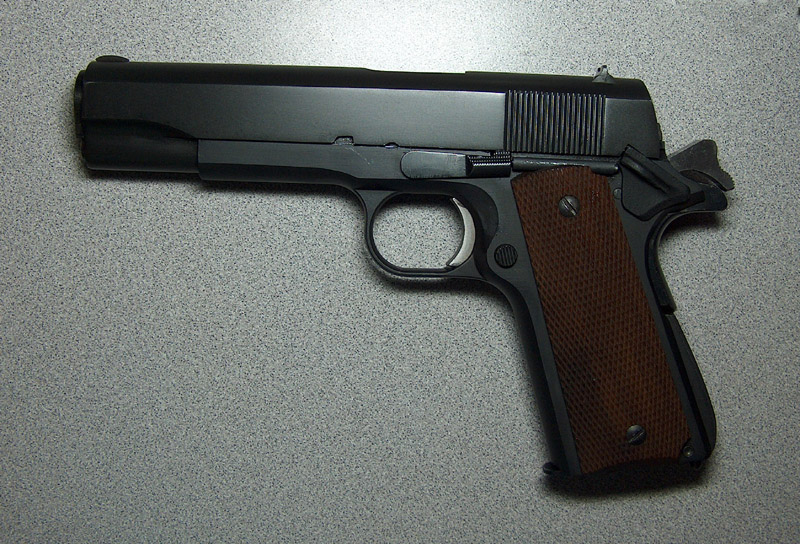
The blank slide lends the gun a smooth, monolithic look.
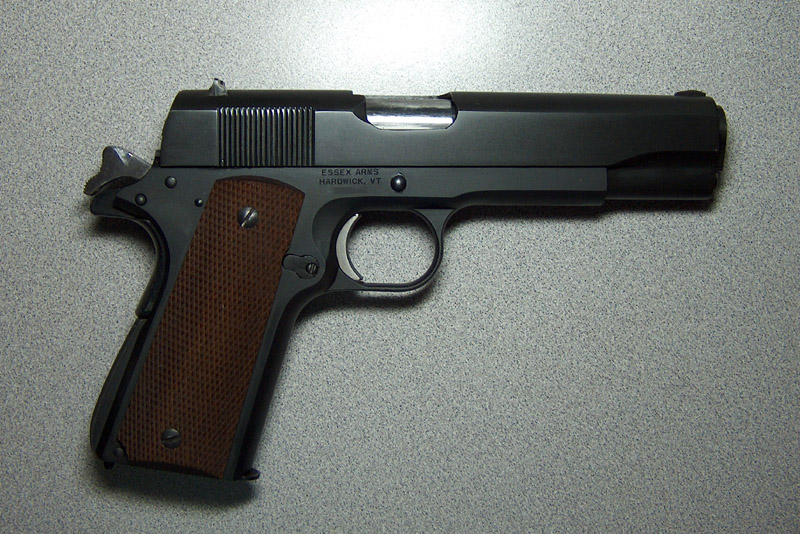
The barrel hood and sides of the hammer were left in the white to match the aluminum trigger.
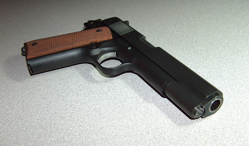
Note the Kart oversized bushing.
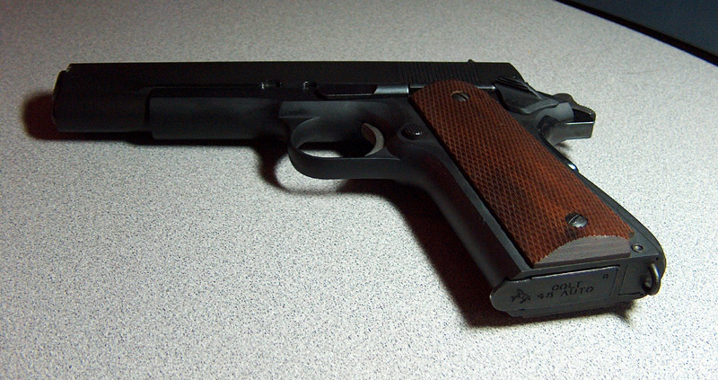
A low angle shot shows the Colt hybrid mag.
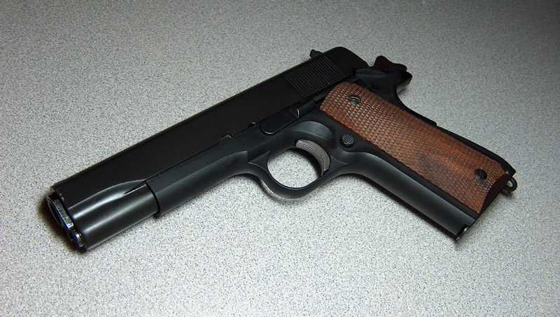
My favorite shot.
I placed an order for a Sarco parts kit and Essex frame on July 17, 2006. Today is July 22, 2007, and I just returned from performing final testing on the 1911. This project has taken almost exactly a year of work. To be fair, there were long stretches of down time while I waited on parts or tools, and weeks where I didn't even touch the thing. I worked slowly and tentatively and set things aside when I started feeling frustrated.
There are a few things to tweak (an oversized firing pin stop, maybe a new extractor, taking the barrel ramp in a bit to compensate for the recut frame ramp, etc.), but then there will always be things to fix, enhance, redo, or replace. The trick is knowing when to call things complete, and now is as good a time as any. Feeding is reliable, extraction is reliable, if erratic, and the trigger is good. The final product is not worth the money invested, but when combined to the time, experience, and learning, it's worth every penny and then some.
The experience itself has been enlightening, infuriating, and enjoyable in roughly equal measures. As a kid I enjoyed building plastic models, and this project brought back the fun of watching something take shape and working with one's hands that I'd all but forgotten. I thought I had a good knowledge of the way 1911s work before starting, but what I've learned since then led me to realize that I really didn't know that much at all, and makes me wonder what I don't know now that remains to be learned. I expected to get frustrated, and boy were those expectations ever fulfilled. The 1911 project has had its ups and downs, so I'm both happy and sad to bring it, and this account thereof, to a close.
Now it's time to build another.
There are a number of people who deserve thanks for their assistance with this project. Without the help of those listed below, building my own 1911 would have permanently stalled at several points, produced a much-inferior product, would never have even begun, or would never have even been thought possible.
First, I must thank my wife not only for being so supportive and encouraging of what is a ludicrously expensive hobby, but also for being a consistant anchor of sanity and clear-headed perspective. When I did something right, she graciously pretended to be impressed at my ability to take $200 and three weeks' time doing what's done in ten minutes by underpaid Brazilians in Imbel's factories; when I was frustrated and depressed by failure or lack of progress, my dark feelings were always tempered by the knowledge that though I might be the owner of a nonfunctional 1911 apparently made out of compressed money, at least my wife was a wonderful human being. I love you, sweetie!
Thanks are also richly deserved by Lazarus, whose assistance and knowledge has proven invaluable. His instruction in chamber reaming and trigger jobs demystified and made simple the two scariest and hardest parts of 1911 construction, and I continue to learn from his experience. Everyone should be so lucky to have a guide as knowledgeable and generous as he. Also, his love of 1911s and S&W revolvers mark him as a man of superb taste in handguns.
Without the incredibly informative posts of 1911Tuner, I probably would never have acquired any interest in what goes on inside firearms in the first place, let alone a desire to build one. Anyone can say, "do this to fix the problem" but few people have the ability or desire to explain why the problem is occurring or why the prescribed solution will work. 1911Tuner does, and his writeups on various functions of the 1911 are what made me realize that if you are willing to sit and think about it for a while, the 1911 will hold no secrets. His hospitable willingness to share information is one of the best demonstrations of the adage, "give a man a fish, and he's fed for a day; teach a man to fish, and he'll never go hungry." He deserves to be richly thanked for the help and information he's given so many, so patiently; I'm only one small example.
Thanks also go out to John Caradimas, who runs M1911.org. This site is the best single source of information on the 1911 on the internet, and its forums are the single most pleasant and civil discussion forums I've found on the internet, thanks in no small part to his dilegent and mature moderation.
There are also no small number of posters in the M1911.org gunsmithing forums whose helpful tips managed to get me back on track many times. All those who've ever offered a suggestion in response to one of my posts, or at least restrained the impulse to call me a dummy, deserve thanks as well.
Finally, I'd like to thank you for visiting my site and taking the time to read this writeup.
I wanted to call this section "For the Love of God, At Least Read This Page Before Building a 1911", but it wouldn't fit in the menu bar. Here are listed all the hard-learned lessons that I wish I had known before beginning. They are provided for the edification of those who would otherwise have made the mistakes I had a chance to avoid. A wise man learns from his mistakes, but a wiser man learns from the mistakes of others. Be smarter than I was by learning the lessons from me that I had to learn the hard way.
When reading about parts selection for 1911 builds or repairs, the common theme to all advice given is, "buy quality parts." I distinctly remember snorting at such advice: "What a bunch of name-brand parts snobs," I thought. "Surely it is possible to build a functional 1911 without resorting to fancy- schmancy overpriced name-brand components!"
I was right, sort of. It is possible to build a 1911 out of el cheapo components, just like it's possible to fall out of an airplane at 30,000 feet and survive. That doesn't mean making one's plans contingent on a possibility is at all advisable.
It's not fitting that was the big issue for me; that was expected. The problems came from parts that were simply of bad quality, which no amount of fitting can fix, or cheaping out when replacing these low-quality parts and ending up with equally deficient components. In other words, if you have to upgrade, take the opportunity to make it a significant improvement; your life will be easier for it.
Then there are some parts that are important enough to warrant not even trying to make the budget alternative work. Although others' experiences may be different, I wish I had invested a little more in the slide, frame, barrel, and ignition system right off the bat.
The slide that came with my parts kit was unmarked, but I later learned it was probably a Rock Island Armory part. My guess is that Sarco got a lot of them for cheap due to dimensional issues, the same ones that ended up giving me grief. For starters, the rear of the slide was cut with the wrong radius, so it sits forward of the end of the frame and there's nothing I can do to fix it. (I'm not the only one who ran into this problem with these slides.) There was also the width of the breech face, which required extensive modification to even get the gun working in the first place.
Then there's the whole barrel saga, the pain of which owes a lot to my own poor choices in replacement barrels and gunsmiths. The parts kit barrel was pretty low quality, with casting seams on the lower lugs. The replacement Auto-Ordnance part came with rust on it and didn't engage the upper lugs too deeply. Fortunately (sort of), it got mangled by the guy I paid to finish the chamber. The Kart barrel, though expensive and difficult to fit, turned out to be far superior to both of the prior choices. A good part, even if it requires effort to get working, is ultimately less painful than a low-quality part, because properly-directed effort actually produces good results.
The frame was supposedly a step up from the no-name frames, but it wasn't without its headaches. The frame ramp was cut too steep, and although Essex recut it, the shallow magwell angle remains unfixed. Unfortunatley, the market for 1911 frames doesn't offer a lot of outstanding good choices, as people have reported issues with Essex frames, and even buying a 1911 for its frame and slide doesn't guarantee in-spec parts.
The ignition system saw every part but the disconnecter replaced in pursuit of an acceptable trigger pull. The Colt hammer I eventually ended up using was head and shoulders above the one that came with the kit, as was the Ed Brown sear, whose factory-set primary angle needed just a spot of polishing.
In fact, the only pieces in the parts kit that saw neither extensive fitting nor ultimate replacement were most of the pins, the firing pin stop, the grip safety, the recoil spring plug and recoil spring guide rod, and the grip screws. Everything else either saw the file, the stones, or the rubbish bin.
I have to emphasize, though, that if I could go back in time and advise myself on parts selection, the only thing I would change is the choice of replacment barrels (I would have skipped the Auto-Ordnance barrel entirely), and maybe the frame. The parts kit itself made for a great learning experience and I heartily recommend it for anyone who wants to dive in the deep end and doesn't mind carrying a bag of cement while doing so. Just be sure not to cheap out when the time comes up get a better part. And if your goal is to just build the gun with minimal pain, then spending a few extra bucks will save you many extra hours of fitting time.
So if you sneer at what appear to be parts snobs, know that I did the same and now have the scars on my knuckles to prove me wrong.
1911s can be detail-stripped using nothing more than the gun itself, but the same is definitely not true of building one from parts. Anyone who builds things for a job or hobby knows that the right tools make a hard job easy, and now so do I. Initially, though, the purchase of each additional tool was done with gritted teeth, instead of the jubilation that should rightly accompany the acquisition of tools.
This was really stupid, because every time I bought a specialized tool, or even a general-purpose tool of decent quality, I was amazed not only by how much quicker and easier it made things, but also at how much better the final product became.
Initially, I tried to get by with my set of hobby files and sandpaper. This worked okay for most fitting, but then my descriptions gloss over the time and frustration involved. "I fitted the slide stop," just rolls off the tongue better than, "I filed on the slide stop for 45 minutes while swearing under my breath, inhaling metal shavings, and skinning two knuckles on my left hand because the file was too big." Toward the end of the process, though, I wised up and starting getting the tools I needed, such as the #2 pillar file to widen the breech face and the plate glass for flat surface sanding. Thankfully, I'd learned my lesson before trying to do a trigger job or move the barrel ramp back, since I shudder to think of what would have happened if I'd tried to do those without stones or a scrape, respectively.
I just wish I'd known from the start, though, how many special tools were needed so that it wouldn't have been dismaying to discover. Here's a short list of the equipment I had to buy, borrow, build, or use to make this 1911:
caliper with thousandths precision
hobby files
#2 Swiss cut pillar file
smooth mill file
machinist's scrape
300, 400, 600, and 800-grit sandpaper
plate glass for the sandpaper
sear jig
medium, fine, and extra-fine stones
GO and NO-GO gauges
brass punches
steel punches
roll pin punches
Kart barrel-fitting kit
.45 ACP chamber finishing reamer
tap wrench
tapping fluid
magnifying glass
sear and hammer frame pins
800-grit lapping compound
cold-bluing liquid
gun-scrubber (or non-chlorinated brake cleaner)
feeler gauges
trigger pull gauge
barrel vice
Dremel and assorted attachments
0.7 inch diameter long wrench socket
Aluma-Hyde finishing spray
Play-Doh
graphite
lipstick
Sharpie markers
brass hammer
bench block
tweezers
small vice
large bench vice
Band-Aids; lots and lots of Band-Aids
solid vertical wall against which a head may be banged
A lathe, mill, and drill press would also have come in handy, but I had to make do; hence, the bandages. Note that the above list is just for fitting parts, with no major alterations required on my part. Had I wanted to do stuff like install new sights, recut the frame ramp myself, or tighten the frame-to- slide fit, any of those would have made the above list much longer and more expensive. Another thing to note is that when you're done building a 1911, you'll be left with a number of tools that aren't useful for anything but working on 1911s. This isn't a problem if you plan to do more, but the additional expense might make it not worth it for just a single pistol.
The most frustration I ever experienced while working on this gun came when I started caring more about producing a working 1911 than the act of building a 1911. When that happened, problems became obstacles blocking a goal instead of opportunities to learn more and do interesting things.
This was a lesson I learned over and over again, although one could argue that if the principle had to be rediscovered multiple times it was never really internalized in the first place. I just kept getting excited at the prospect of having a working 1911 and forgetting that if I just wanted a 1911, it would have been quicker, cheaper, easier, and less frustrating to just go out and buy one.
But that wasn't the point. At the risk of stating the obvious, the point of building a 1911 is not to have a 1911, but to build a 1911. The work involved in doing so can be frustrating, and anything that multiplies that frustration (e.g. a tight budget, short timeline, or strong desire for the result) will quickly turn an enjoyable journey into an arduous trek.
Maybe it's cost-effective for professional custom 1911 manufacturers to toss together a gun for their own use, but the economics of large-scale manufacturing being what they are, an amateur would be hard-pressed to build a bargain, especially when factoring in the cost of his own time. For those with a borderline-pathological interest in the internals of the M1911, though, keeping eyes on the process, not the goal, will make it worth the effort.